1
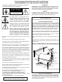
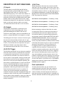
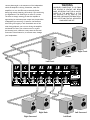
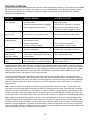
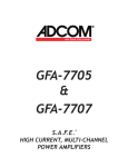
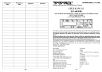
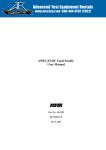
OWNER’S MANUAL
GFA-7605
& GFA-7607
Multichannel High-Current Power Amplifiers
WELCOME
Dear fellow ADCOM product owner,
Welcome to the ADCOM family! For more than twenty years, ADCOM products have delivered
excellent performance and value for customers around the world. Our products are designed by
our experienced and demanding engineering team, built to the highest standards in our factory,
and sold and serviced through dealers, custom installers, and other retailers whose primary goal
is your complete satisfaction.
We know you are anxious to hear your new amplifier in action, but please take a few minutes
to read this owner’s manual before connecting the amplifier to your system. Because ADCOM
amplifiers can output tremendous power, it is particularly important that you connect your
amplifier to your pre-amplifier and speakers while the amplifier is unplugged and your other
equipment is turned off. This will protect the amplifier and other equipment from potential short
circuits from crossed interconnect or speaker wires while you are working on the connections. In
addition, it is important that you allow for adequate ventilation around your amplifier and other
equipment, since excessive heat buildup can shorten the life of any electronic product, including
the amplifier. Once you have correctly connected your pre-amplifier and speakers to your new
amplifier, you should be able to enjoy many trouble-free years of performance.
We conduct a thorough quality and performance test on each and every amplifier we build in our
factory prior to shipment. In the rare case of a defect that may occur after shipment, we stand
behind our amplifiers with a five year parts and labor warranty. To register for this warranty,
please complete and mail the enclosed warranty card back to ADCOM. Also, please keep a copy of
your sales receipt with the owner’s manual so you may provide proof of eligibility for the warranty
should the need arise.
We know you will be very happy with the sound and performance of your new amplifier. We
hope you will also consider other ADCOM products, such as our line of pre-amplifiers and DVD
and CD players. In addition, we design and manufacture complementary products such as line
conditioners/surge suppressors and speaker selectors. Please visit our web site, www.adcom.com,
to learn more about our complete line of stereo, home theater, and distributed audio/video
products.
On behalf of all of us at ADCOM, I want to thank you for your selection of our product for your
home or business entertainment system.
Sincerely,
Douglas Klein
President
ADCOM
2
TABLE OF CONTENTS
WELCOME . . . . . . . . ................................ 2
SAFETY INFORMATION ........................... 4
DESCRIPTION OF UNIT
GFA-7605 FEATURES .............................. 5
GFA-7607 FEATURES .............................. 5
WARRANTY INFORMATION ......................... 5
INSTALLATION & HOOKUP
UNPACKING THE GFA-7605/7607 .................. 6
INSTALLING THE GFA-7605/7607 .................. 6
CONNECTING THE GFA-7605/7607 ................. 7
OPERATION
FRONT AND REAR PANEL DIAGRAMS ................ 8
DESCRIPTION OF UNIT: REAR PANEL ............ 9-10
DESCRIPTION OF UNIT: FRONT PANEL .......... 10-11
CONNECTIONS DIAGRAM ......................... 11
TROUBLESHOOTING
RESOLVING PROBLEMS ........................... 12
CARING FOR YOUR GFA-7605/7607 ............... 13
SERVICE INFORMATION .......................... 13
GFA-7605 SPECIFICATIONS ....................... 14
GFA-7607 SPECIFICATIONS ....................... 15
N
OCK
THE FOLLOWING PRECAUTIONS AND SAFETY INSTRUCTIONS
ARE REQUIREMENTS OF UL AND CSA SAFETY REGULATIONS
Warning: To reduce the risk of fire or electric shock, do
not expose this unit to rain or moisture.
CAUTION
RISK OF ELECTRIC SHOCK
DO NOT OPEN
CAUTION
The graphic symbol of a lightning flash with an
arrow point within a triangle signifies that there
is dangerous voltage within the unit and it poses
a hazard
to anyoneSHOCK
removing the cover to gain
RISK
OF ELECTRIC
access to the interior of the unit. OnIy qualified
DO
NOT
OPEN
service personnel should make any such attempt.
The graphic symbol of an exclamation point within
an equilateral triangle warns a user of the device
that it is necessary to refer to the instruction manual
and its warnings for proper operation of the unit.
Do not place this unit on an unstable cart, stand, tripod,
bracket, or table. The unit may fall, causing serious
injury to a child or adult, and serious damage to the
unit. Use only with a cart, stand, tripod, bracket, or
table recommended by the manufacturer or sold with
the unit. Any mounting of the device should follow the
manufacturer’s instructions, and should use a mounting
accessory recommended by the manufacturer.
ATTENTION
POUR PREVENIR LES CHOCS ELECTRIQUES NE PAS UTILISER CETTE FICHE
POLARISEE AVEC UN PROLONGATEUR, UNE PRISE CE COURANT OU UNE
AUTRE SORTIE CE COURANT, SAUF SI LES LAMES PEUVENT ETRE INSEREES
A FOND SANS EN LAISSER AUCUNE PARTIE A DECOUVERT.
CAUTION
TO PREVENT ELECTRIC SHOCK DO NOT USE THIS POLARIZED PLUG WITH
AN EXTENSION CORD, RECEPTACLE OR OTHER OUTLET UNLESS THE
BLADES CAN BE FULLY INSERTED TO PREVENT BLADE EXPOSURE.
CAUTION POWER LINES
Any outdoor antenna must be located away from all power lines.
OUTDOOR ANTENNA GROUNDING
If an outside antenna is connected to your tuner or tuner/preamplifier,
be sure the antenna system is grounded so as to provide some protection
against voltage surges and built-up static charges. Section 810 of the
National Electrical Code, ANSI/NFPA No. 701984, provides information
with respect to proper grounding of the mast and supporting structure,
grounding of the lead-in wire to an antenna discharge unit, size of
grounding conductors, location of antenna discharge unit, connection to
grounding electrodes, and requirements for the grounding electrode.
a. Use No.10 AWG (5.3 mm2) copper, No.8 AWG (8.4 mm2) aluminum, No.17
AWG (1.0 mm2) copper clad steel or bronze wire, or larger, as a ground wire.
b. Secure antenna lead-in and ground wires to house with stand-off
insulators spaced from 46 feet (1.221.83 m) apart.
Read all the safety and operating instructions before connecting or using
this unit.
c. Mount antenna discharge unit as close as possible to where lead-in enters
house.
Retain this notice and the owner’s manual for future reference.
d. Use jumper wire not smaller than No.6 AWG (13.3 mm2) copper, or the
equivalent, when a separate antenna grounding electrode is used. See NEC
Section 810-21 (j).
All warnings on the unit and in its operating instructions should be adhered to.
All operating and use instructions should be followed.
Do not use this unit near water. For example, near a bathtub, washbowl,
kitchen sink, laundry tub, in a wet basement, or near a swimming pool.
EXAMPLE OF ANTENNA GROUNDING AS PER NATIONAL ELECTRICAL CODE
INSTRUCTIONS CONTAINED IN ARTICLE 810. RADIO AND TELEVISION EQUIPMENT.
power lines
The unit should be installed so that its location or position does not interfere
with its proper ventilation. For example, it should not be situated on a
bed, sofa, rug, or similar surface that may block the ventilation openings;
or placed in a built-in installation, such as bookcase or cabinet, that may
impede the flow of air through its ventilation openings.
ground clamp
service entrance
conductors
standoff
insulators, b
The unit should be situated away from heat sources such as radiators, heat
registers, stoves, or other devices (including amplifiers) that produce heat.
The unit should be connected to a power supply outlet only of the voltage
and frequency marked on its rear panel.
The power supply cord should be routed so that it is not likely to be walked
on or pinched, especially near the plug, convenience receptacles, or where
the cord exits from the unit.
mast
service
entrance
equipment
antenna
lead-in wire
ground wire, a,b
ground clamps
antenna
discharge
unit, c
Clean unit only as recommended in its instruction manual.
The power supply cord of the unit should be unplugged from the wall outlet
when it is to be unused for a long period of time.
Care should be taken so that objects do not fall, and liquids are not spilled,
into the enclosure through any openings.
This unit should be serviced by qualified service personnel when:
A. The power cord or the plug has been damaged; or
B. Objects have fallen, or liquid has been spilled, into the unit; or
C. The unit has been exposed to rain, or liquids of any kind; or
D. The unit does not appear to operate normally, or exhibits a marked
change in performance; or
E. The device has been dropped, or the enclosure damaged.
DO NOT ATTEMPT SERVICING OF THIS UNIT YOURSELF.
REFER SERVICING TO QUALIFIED SERVICE PERSONNEL.
to external antenna
terminals of radio receiver
power service grounding
electrode system
(e.g. interior metal water pipe)
bonding jumper, d
ground wire, a,b
ground clamps
optional antenna grounding
electrode driven 8 feet (2.44 M)
the earth if required by local c
NOTE TO CATV SYSTEM INSTALLER
This reminder is provided to call the CATV system installer’s attention to
Article 82022 of the National Electrical Code that provides guidelines for
proper grounding and, in particular, specifies that the cable ground shall
be connected to the grounding system of the building, as close to the
point of cable entry as practical.
GFA-7605 FEATURES
• Precision-matched devices used throughout the signal path.
• 100,000 µF of power supply-filter capacitance to optimize transient response.
• Independent power supplies for each channel.
• Fewer gain stages improve signal reproduction accuracy.
• Custom toroidal power transformer provides better regulation and greater peak current capability.
• Independent thermal-overload and distortion LEDs for all 5 channels.
• High quality, gold-plated 5-way binding posts.
• High quality, gold-plated RCA jacks.
• Large independent internal heatsinks for greater cooling capability of output devices.
• Convenient 12V DC power ON/OFF triggering.
• Heavy gauge, anodized aluminum front panel.
• Powder-coated, baked chassis and top cover for greater durability.
• Cooling vents for greater efficiency and cooler operation while driving low impedance loads.
GFA-7607 FEATURES
• Precision-matched devices used throughout the signal path.
• 140,000 µF of power supply-filter capacitance to optimize transient response.
• Independent power supplies for each channel.
• Fewer gain stages improve signal reproduction accuracy.
• Custom toroidal power transformer provides better regulation and greater peak current capability.
• Independent thermal-overload and distortion LEDs for all 7 channels.
• High quality, gold plated binding posts.
• High quality, gold-plated RCA jacks.
• Large independent, internal heatsinks for greater cooling capability of output devices.
• Heavy gauge, anodized aluminum front panel.
• Powder-coated, baked chassis and top cover for greater durability.
• Cooling vents for greater efficiency and cooler operation while driving low impedance loads.
ADCOM Protection Plan (USA Only)
ADCOM offers the enclosed valuable Limited Warranty. Please read the details on the Warranty Card carefully to
understand the extent of the protection offered by the Warranty, its reasonable limitations, and what you should
do in order to obtain its benefits. Be sure to verify that the serial number printed on the rear panel matches the
serial number on the outer carton. If any number is altered or missing, or if the ADCOM Warranty Card is not
included in the carton, you should notify us immediately in order to ensure that you have received a genuine
ADCOM product which has not been opened, mishandled, or tampered with in any way. Always retain your
original sales receipt as a proof of purchase.
5
INTRODUCTION
Congratulations on your decision to purchase the GFA-7605 or GFA-7607 multichannel power amplifier. The GFA-7605 and
GFA-7607 have been designed to be high performance and musically accurate in a configuration specifically designed to
integrate with any home theater processor. You have made a wise choice that will reward you for years to come with
exceptionally accurate and musical sound reproduction. To realize the full potential of your new amplifier, and before
making any connections to it, please read these operating and installation instructions thoroughly.
UNPACKING THE GFA-7605/7607
Before your new ADCOM amplifier left our factory, it was carefully inspected for physical imperfections and tested for
all electrical parameters as a routine part of ADCOM’s systematic quality control. This, along with lull operational and
mechanical testing, should ensure a product flawless in both appearance and performance. After you have unpacked the
GFA-7605/07, inspect it for physical damage. Save the shipping carton and all packing material as they are intended to
reduce the possibility of transportation damage, should the amplifier ever need to be shipped again. In the unlikely event
damage has occurred, notify your dealer immediately and request the name of the carrier so a written claim to cover
shipping damages can be initiated. THE RIGHT TO A CLAIM AGAINST A PUBLIC CARRIER CAN BE FORFEITED IF THE CARRIER
IS NOT NOTIFIED PROMPTLY IN WRITING AND IF THE SHIPPING CARTON AND PACKING MATERIALS ARE NOT AVAILABLE FOR
INSPECTION BY THE CARRIER. SAVE ALL PACKING MATERIALS UNTIL THE CLAIM HAS BEEN SETTLED.
INSTALLING THE GFA-7605/7607
During normal home operation the internal heatsinks of the GFA-7605/7607 may become warm. However, there are
instances during high-level playback into low impedances when the heatsinks will become much warmer than usual. To
ensure the amplifier’s long-term, trouble-free operation it is necessary to provide adequate ventilation for the heatsinks.
Therefore, the GFA-7605/7607 should be kept away from external sources of heat such as radiators and hot-air ducts. The
GFA-7605/7607 should never be placed with other heat-producing components in a cabinet or enclosure lacking free air
flow. The top and bottom panel of the amplifier’s chassis have been provided with vents to allow the necessary cooling of
the internal components. It is imperative that these vents are not obstructed in any way.
We recommend that you do not stack other components on top of the GFA-7605/7607. This is particularly important if your
system includes low-impedance loudspeakers which are difficult to drive, or if you will consistently demand high volume
levels from the amplifier and speaker system. Not only will heat generated by the amplifier affect the performance of
equipment stacked on top of the GFA-7605/7607, but the free flow of air through the ventilating slots in the amplifier may
be partially obstructed.
If you observe these recommendations, the GFA-7605/7607 will perform reliably in any reasonable environment. You
should also pay attention to such normal considerations as protection from excessive dust and moisture. Occasional
vacuuming of accumulated dust on the chassis, panels and around the ventilating slots should be all that is required.
The optimal performance of your new GFA-7605/7607 will ultimately depend on the care with which you make the
connections between the amplifier, preamplifier, surround sound decoder and the loudspeakers. All input and output signal
connections should be made only with high quality, low-loss, low capacitance cables following the recommendations in
the Inputs and Outputs section of CONNECTING THE GFA-7605/7607.
6
CONNECTING THE GFA-7605/7607
When connecting the amplifier to the loudspeaker, it is vital to maintain proper polarity (positive to positive, negative
to negative). On the GFA-7605/7607, the positive terminal is color coded RED and labeled “+,” and the negative is color
coded BLACK and labeled “-.” The positive terminal on the speaker will be color coded RED, or will be labeled “+,” “pos,”
“positive,” “8 ohms” or “4 ohms.” The negative terminal on the speaker will be color coded BLACK, or will be labeled “-,”
“neg,” “negative,” “C,” “Common,” “G,” or “ground.”
It is recommended that your speaker cables be terminated with “U” type spade connectors. These will give the most
contact area insuring long-term reliability. The spade connector should have a maximum width of 0.57 inches and an
opening width of no less than 0.25."
To properly connect the speaker cable to the binding posts, turn the insulated head of the binding post clockwise until the
wire or connector is firmly secured. Finger pressure is sufficient and you should not use pliers or other tools which could
damage or over-tighten the binding-post assembly. The binding posts have been designed in such a way that finger pressure
is all that is required to cause a “pinching” action among the different metal surfaces to ensure proper connection.
It is very important to use the correct size of wire in order to avoid unnecessary loss of amplifier power in the cable,
reduction of amplifier damping factor and other undesirable conditions. Sound audio engineering practice suggests the
use of at least AWG16, stranded, copper cable. Recommended capacitance of the speaker wire should not exceed 5OpF
per foot. This insures high frequencies will not be rolled-off.
All loudspeakers having a nominal impedance down to 4 ohms can be connected to and driven by the GFA-7605/7607.
The amplifier can drive these low-impedance speakers at more than adequate power levels with no difficulty. It should
be noted that many loudspeaker systems which are nominally rated at 4 ohms drop in impedance, in some parts of their
frequency range, to as low as 2 ohms (and sometimes less). You will not experience difficulties even with these very low
impedance loads unless you demand excessively high volumes levels from your system.
It is not recommended that you run additional sets of speakers to the GFA-7605/7607. (If you choose to add remote
speakers in another room, it is strongly suggested that a switching system to disconnect the non-home-theater speakers
be incorporated when the surround sound, home theater mode is in operation). A device such as the ADCOM GFS-3 or GFS-6
Speaker Selector is strongly recommended. A Speaker Selector enables you to maintain good sonic integrity while giving
you the flexibility to add speakers throughout your house.
It is suggested that for all the channels follow this chart for speaker lengths and wire gauges. If longer runs are needed, it
is best to consult with your ADCOM Dealer to maximize the performance of your system with your exact conditions.
up to 24 feet
AWGI6
up to 36 feet
7
AWGI4
up to 58 feet
AWGI2
(1)
GFA-7607 REAR PANEL
(3)
(4)
(2)
(5)
GFA-7607 FRONT PANEL
LF
C
RF
RS
RB
LB
LS
distortion alert >
G
thermal protection >
(6)
(7)
(8)
F
A
7607
(9)
(1) Input Jacks
(6) On/Off Switch
(2) Output Binding Posts
(7) Power LED
(3) I2V DC Trigger
(8) Thermal Protection LEDs
(4) AC Fuse
(9) Distortion Alert LEDs
(5) AC Power Cord
8
DESCRIPTION OF UNIT: REAR PANEL (4) AC Fuse
The AC Fuse protects the electronic circuits of the GFA7605/7607. This fuse, normally, will fail only if there is an
overload within the GFA-7605/7607. It may, however, fail if
the amplifier attempts to deliver very high power into very
low-impedance loudspeakers. In either case, BE SURE TO
REPLACE THE AC Fuse ONLY WITH AN EXACT REPLACEMENT
FUSE. The proper fuse values are:
(1) Inputs
The audio inputs for the GFA-7605 and GFA-7607 are
through high-quality, gold-plated RCA jacks to minimize
high-frequency losses, noise, etc. They will accept
standard RCA-type plugs, one for each of the channels. To
insure that the performance designed into the amplifier is
preserved, you should use the highest quality audio cables
possible. There are many cables which are color-coded
and specifically designed for this application. Your ADCOM
dealer can help select the best cable for your needs.
GFA-7605 for 120 volt operation — Fuse Rating: 13 Amp
GFA-7605 for 230 volt operation — Fuse Rating: 6.5 Amp
(See CONNECTING THE GFA-7605/7607 for more information).
GFA-7607 for 120 volt operation — Fuse Rating: 15 Amp
(2) Outputs
GFA-7607 for 230 volt operation — Fuse Rating: 8 Amp
The GFA-7605’s and GFA-7607’s connections to the
Before attempting to replace a failed fuse, be certain
to unplug the AC Power Cord from the AC wall outlet to
prevent possible electrical shock. Replace the AC Fuse
only with one identical in type and rating as printed on
the rear panel. DO NOT USE ANY SUBSTITUTE FUSES WITH
DIFFERENT RATINGS OR VALUES. Failure to observe this
precaution may cause serious damage to the amplifier
circuits, may create a hazard fire, and may void the warranty.
If the Power LED (7) does not glow, it may be an indication
that the AC fuse has blown. If you are using the 12V
DC Triggering feature it may be possible that there is
a problem with that connection. To determine if the
problem is caused by a malfunction in the 12V DC system,
remove the small plug inserted into the I2V DC Triggering
jack. Press the front panel power switch to turn off the
amp, and immediately re-press the power switch. If the
problem is caused by the 12V DC triggering circuit the amp
will turn on and the LED will glow. DO NOT attempt repair
of the 12V DC system. If you are not sure, or the amplifier
displays other symptoms, please consult the RESOLVING
PROBLEMS section on page 12.
loudspeakers are made through high-grade, 5-way,
gold-plated binding post terminals. There are two
terminals for each speaker, which are colored RED for the
positive (+) output and BLACK for the negative (-) output.
The binding posts will accept a variety of connector types;
the most secure and prevalent of these is the “U”-type
spade connectors (at least 0.25’’ wide and maximum width
of 0.57”). The terminal will also accept bare wire (up to
AWG1O) and “banana” type plugs (single or dual).
(See CONNECTING THE GFA-7605/7607 for more information).
(3) I2V DC Trigger
The GFA-7605 and GFA-7607 are very high power amplifiers
and as such must be directly connected to the wall outlet
or an appropriate surge protector or AC line conditioner.
It must never be connected to the ‘switched’ outlets on
the rear panel of a pre-amplifier. Usually this would mean
that when you turn on/off your pre-amplifier you would
have to turn on/off your power amplifier separately. We
have however provided the ability to control the OFF/ON
function of the GFA-7605/7607 by a l2V DC output jack
on the rear of certain ADCOM pre-amplifiers and tuner
preamplifiers. When using this feature the front panel
Power Switch must be left in the in “on” position. To
connect you will need a monaural mini phone plug to
monaural mini phone plug cable of appropriate length (not
included) to reach from the rear panel of the amplifier to
the rear panel of the pre-amplifier. Contact your dealer for
information on using this feature with ADCOM and other
brand pre-amplifiers.
Fuse replacement
To remove the fuse-holder cap, you will need a 1/4”
standard flat-blade screwdriver. Place the screwdriver
in the recessed slot in the cap. Turn the cap 1/8-turn
counter-clockwise, until the cap pops out towards you.
Grasp the cap with your fingers and pull it completely out.
The fuse is inserted in the back of the cap; gently pull it free.
9
Since the fuse has a ceramic body and you cannot visually
examine the fuse element it is therefore suggested that
you replace it with an identical substitute or bring the fuse
to your ADCOM dealer so they may check its integrity. To
replace the fuse, insert it in the back of the fuse-holder
cap. Place the cap into the fuse-holder. Place the
screwdriver in the recessed slot, gently press in and turn
1/8-turn clockwise.
(5) AC Power Cord
The AC cord provides power to operate all the GFA7605/7607’s circuits. Its plug can be connected to a
standard wall outlet provided the outlet supplies a voltage
compatible with the power requirements printed on the
rear panel of the GFA-7605/7607.
listening levels, etc. If the AC Fuse (4) has not failed, the
Power LED is out, and the Thermal Protection LED (9) does
not glow, this would indicate that the thermostat within
the transformer has opened.
Once the temperature within the transformer decreases
to a normal level, the thermostat will reset itself
automatically and normal operation will resume. If you
are to avoid tripping the thermostat in the transformer
continually, you must reduce the sound level demands,
correct the load impedance of the loudspeakers, or both.
(8) Thermal Protection LEDs
(7) Power LED
The GFA-7605/7607 are provided with a thermal protection
circuit which will shut down the individual amplifiers
if its heatsink temperature reaches 85°C. The Thermal
Protection LEDs will light whenever the thermal protection
circuit in its respective channel has been triggered and the
amplifier is inoperative. The thermal protection circuitry
will typically be triggered by very high power demands
into impedances much lower than the amplifier is capable
of driving at those levels. If any amplifier channel’s
output through the loudspeaker(s) ceases abruptly, and
its Thermal Protection LED glows, you will know that its
heatsink temperature has become unacceptably high
and the circuitry is protecting the amplification devices.
Please note that the Power LED (7) will remain on and the
amplifier will still be energized. Once the temperature
of the heatsink(s) drops to a safe operating level, that
amplifier will automatically resume operation.
This LED will glow whenever the On/Off Switch (6) is
turned on and the GFA-7605/7607 is energized. The Power
LED indicates that there is AC voltage being fed to the
amplifier, but it does not signify that all the amplifier’s
circuits are in operation. If, for example, one of the
Thermal Protection LEDs (9) glows, that amplifier channel
will not produce sound even though the Power LED may
still glow. When the GFA-7605/7607 is turned off, the
Power LED will take some time to fade out completely. It
may take up to 30 seconds to fully extinguish.
Activation of the Thermal Protection circuitry in any
of the amplifiers in the GFA-7605/7607 is an indication
that the amplifier has been over-driven or that the
load the loudspeakers are presenting to the amplifier
is unreasonably low. If you wish to prevent recurrent
activation of the thermal protection circuitry, you must
reduce the volume-level demands or correct the load
impedance condition which may be causing activation of
this circuitry.
DESCRIPTION OF UNIT: FRONT PANEL
(6) On/Off Switch
The On/Off Switch controls power to the power
transformer and circuits of the GFA-7605/7607. Whenever
the GFA-7605/7607 is energized the Power LED (7)
will glow. To turn the GFA-7605/7607 on, press the
push-button. It will remain in the “engaged” position while
the unit is energized. To turn the GFA-7605/7607 off, press
the push-button in and release and it will move to the
“disengaged” position.
Additionally, the internal power transformer is provided
with a thermostat which will interrupt power into the
transformer if its temperature exceeds 125°C. This high
temperature will seldom, if ever, be encountered unless
the amplifier is subjected to abnormal conditions, such
as operation into loads of less than 3 ohms at very high
(9) Distortion Alert LEDs
The Distortion Alert circuit is a unique ADCOM distortion
detection system which reads all forms of non-linear
distortion such as THD, IM, slew-induced, “clipping,” etc.
The Distortion Alert LEDs will light when distortion reaches
approximately 1% regardless of impedance, voltage/
10
WARNING
current phase angle or the reactance of the loudspeakers
which the amplifier is driving. Sometimes, when the
amplifier is in use, the LEDs may occasionally flicker
during high volume listening, particularly if you are driving
low impedances. This flickering is no cause for concern.
The LEDs are simply warning you that the amplifier is
approaching its maximum power output into the particular
loudspeakers you are using. If, however, the Distortion
Alert LEDs glow brightly or are illuminated most of the
time during playback, you are over driving the amplifier
and should turn down your volume control to reduce
the listening level, otherwise it may cause the Thermal
Protection to be activated or, in extreme cases, damage
your loudspeakers.
WHENEVER CONNECTIONS TO OR FROM
THE GFA-7605 & GFA-7607 ARE BEING
MADE, BE CERTAIN THAT THE AC ON/OFF
SWITCH OF THE AMPLIFIER IS IN THE
OFF POSITION, THE AC CORD OF THE
AMPLIFIER IS DISCONNECTED FROM THE AC
WALL OUTLET AND THAT ALL ASSOCIATED
COMPONENTS ARE OFF.
Right Front
Center
Left Front
Right Back
Right Surround
Left Surround
Left Back
RESOLVING PROBLEMS
Use the chart below to solve common situations that don’t require professional attention. If the steps stated in POSSIBLE
SOLUTION do not resolve your problem, then please contact your ADCOM Dealer or call the ADCOM Customer Service
Department. Any problems not covered here should be brought to the attention of your ADCOM Dealer or ADCOM
Customer Service Department.
SYMPTOM
POSSIBLE REASON
POSSIBLE SOLUTION
Power LED does not
glow. No sound
AC Power Cord(s) not plugged in.
AC Fuse(s) failed.
Transformer thermal protection engaged.
I2V DC triggering malfunctioning.
Power LED glows,
but no sound
Preamp or source unit is not on.
Connections in rear of amp are loose.
Plug in AC Power Cord(s).
Replace AC Fuse(s).
Wait until unit cools down. It will reset.
Reset power switch manually. Check
connection of 12V DC trigger at source.
Make sure whole system is on.
Verify all connections on rear of amp.
One channel not
producing sound
INPUT(s) or OUTPUT(s) connector
disconnected or loose.
Verify both connections on that channel.
Hum from all speakers
at any volume
Hum from all speakers
(hum goes up or
down with volume)
Hum from the amplifier
itself
Speaker disconnected.
Internal protection engaged.
Ground loop (difference in ground voltages
between components).
Problem with source unit (CD, tape, etc.),
or RCA cable connecting that source unit
to the preamp.
Some major appliance, dimmer, halogen or
fluorescent light is creating interference.
Verify connection at speaker.
Bring to Dealer or Service Center.
If Cable TV is present (see Note 1).
If Cable TV is not present (see Note 2).
Try different source (tuner, tape, etc.)
and/or different RCA cable.
Make sure all appliances, dimmers and
suspect lights are off.
A special note on “hum:” When there is a low-volume “hum” audible throughout your speakers, even with the main
volume turned all the way down, you have a common phenomenon known as a “ground loop.” A ground loop is basically
a difference in ground voltages between two or more components which are connected electrically and which creates
multiple current paths where there must only be one. This difference in potentials creates a 60Hz low-level sound
(approximately a low A), that seems to “hum,” hence the name.
It can be caused by adding new components to your system, but that does not imply there is anything electrically
wrong with any new component. With the advent of audio/video and home theater systems, the problem has become
commonplace. Generally, the cause is the Cable-TV incoming signal line. This new incoming line may add an additional
ground at a different potential to the AC line ground of your other equipment (refer to Note I and 2, to troubleshoot
a hum problem).
Note 1: Cable TV systems can sometimes contribute to ground loop problems which cause “hum.” To determine if your
cable system is the contributing factor, disconnect the Cable-TV incoming signal line (round, 75Ω) at the wall, or the first
component the cable is connected to (i.e. the cable box, or VCR). If the hum is no longer present, you must insert a “75Ω
Ground Loop Isolator” before reconnecting the line. You should check with your ADCOM Dealer to obtain one. If the “75Ω
Ground Loop Isolator” works only partially or not at all, then please read Note 2 to complete the troubleshooting procedure.
Note 2: Make sure that the power amplifier is at least 6” from the Preamp and/or Processor. Usually putting another
component between them is sufficient to minimize the hum. If this does not reduce the hum, turn the system off and
disconnect all Inputs from the amplifier. If the hum still persists, then your Dealer or Service Center must examine the
amplifier. If the hum disappears, try another set of RCA cables. Connect one RCA cable at a time to see if one specific
cable is responsible. If any or all cables cause the hum to appear, then the preamp or processor should be evaluated for
proper operation by your Dealer or Authorized Service Center.
12
CARING FOR YOUR GFA-7605/7607
Great care has been taken by ADCOM to ensure that your amplifier is as flawless in appearance as it is electronically.
The front panel is a heavy-gauge, high-grade aluminum extrusion carefully finished and anodized for durability. The
chassis, top cover and rear panel are heavy-gauge steel that has been powder coated and baked to ensure a lasting
finish. If the front panel, top or sides become dusty or fingerprinted, they can be cleaned with a soft lint-free cloth,
slightly dampened with a very mild detergent solution or glass cleaner.
Do not spray or pour liquids of any kind directly onto the GFA-7605/7607.
SERVICING
ADCOM has a Technical Service Department to answer questions pertinent to the installation and operation of your unit.
In the event of difficulty, please contact us for prompt advice. If your problem cannot be resolved through our combined
efforts, we may refer you to an authorized repair agency, or authorize return of the unit to our factory. To aid us in
directing you to a convenient service center, it would be helpful if you indicate which major city is accessible to your home.
Please address mail inquires to:
Phone, Fax or Email inquires to:
ADCOM Service
8551 East Anderson Drive, Suite 105
Scottsdale, Arizona 85255 USA
Voice: (480) 607-2277
Fax: (480) 348-9876
Monday through Friday
9:00 AM to 5:00 PM MST
Email: [email protected]
For Fax inquires, please include a return Fax number for the reply. When calling or writing about your GFA-7605/7607, be
sure to note and refer to its serial number as well as the date of purchase and the dealer from whom it was purchased.
In any communications to us, please include a daytime phone number where we may reach you. In the event the unit
must be returned to our factory for service, you will be instructed on the proper procedure when you call or write for a
Return Authorization. UNDER NO CIRCUMSTANCES SHOULD YOUR UNIT BE SHIPPED TO OUR FACTORY WITHOUT PRIOR
AUTHORIZATION, OR PACKED IN OTHER THAN ITS ORIGINAL CARTON AND FILLERS.
If the original shipping carton and its fillers have been lost, discarded, or damaged, a duplicate carton may be obtained
from our Service Department for a nominal charge.
Always ship PREPAID VIA UNITED PARCEL SERVICE (UPS) OR OTHER APPROVED CARRIER. DO NOT SHIP VIA PARCEL POST,
since the packing was not designed to withstand rough Parcel Post handling.
FREIGHT COLLECT SHIPMENTS WILL NOT BE ACCEPTED
UNDER ANY CIRCUMSTANCES.
13
GFA-7605 SPECIFICATIONS
Power Rating (To EIA/CEA-490-A Requirements)
125 Watts continuous average power per channel into 8 ohms at any frequency between 20Hz and 20kHz with all
channels driven at less than 1.00% THD.
175 Watts continuous average power per channel into 4 ohms at any frequency between 20Hz and 20khz with all
channels driven at less than 1.00% THD.
IM Distortion (SMPTE)
1 watt to 125 watts into 8 ohms. . . . . . . . . . . . . . . . . . . . . . . . . . . . . . . . . . . . . . . . . . . . . . . . . . . . . . . . . . ≤ 0.075%
1 watt to 175 watts into 4 ohms. . . . . . . . . . . . . . . . . . . . . . . . . . . . . . . . . . . . . . . . . . . . . . . . . . . . . . . . . . ≤ 0.075%
IM Distortion (CCIF, Any Combination from 4kHz to 20kHz)
125 watts into 8 ohms. . . . . . . . . . . . . . . . . . . . . . . . . . . . . . . . . . . . . . . . . . . . . . . . . . . . . . . . . . . . . . . . . . ≤ 0.025%
175 watts into 4 ohms. . . . . . . . . . . . . . . . . . . . . . . . . . . . . . . . . . . . . . . . . . . . . . . . . . . . . . . . . . . . . . . . . . ≤ 0.025%
THD + Noise at 125 watts into 8 Ohms (Typical)
20Hz. . . . . . . . . . . . . . . . . . . . . . . . . . . . . . . . . . . . . . . . . . . . . . . . . . . . . . . . . . . . . . . . . . . . . . . . . . . . . . . . 0.012%
1kHz. . . . . . . . . . . . . . . . . . . . . . . . . . . . . . . . . . . . . . . . . . . . . . . . . . . . . . . . . . . . . . . . . . . . . . . . . . . . . . . . 0.012%
10kHz. . . . . . . . . . . . . . . . . . . . . . . . . . . . . . . . . . . . . . . . . . . . . . . . . . . . . . . . . . . . . . . . . . . . . . . . . . . . . . . . 0.02%
20kHz. . . . . . . . . . . . . . . . . . . . . . . . . . . . . . . . . . . . . . . . . . . . . . . . . . . . . . . . . . . . . . . . . . . . . . . . . . . . . . . . 0.02%
THD + Noise at 175 watts into 4 Ohms (Typical)
20Hz. . . . . . . . . . . . . . . . . . . . . . . . . . . . . . . . . . . . . . . . . . . . . . . . . . . . . . . . . . . . . . . . . . . . . . . . . . . . . . . .
1 kHz. . . . . . . . . . . . . . . . . . . . . . . . . . . . . . . . . . . . . . . . . . . . . . . . . . . . . . . . . . . . . . . . . . . . . . . . . . . . . . .
10kHz. . . . . . . . . . . . . . . . . . . . . . . . . . . . . . . . . . . . . . . . . . . . . . . . . . . . . . . . . . . . . . . . . . . . . . . . . . . . . . .
20kHz. . . . . . . . . . . . . . . . . . . . . . . . . . . . . . . . . . . . . . . . . . . . . . . . . . . . . . . . . . . . . . . . . . . . . . . . . . . . . . .
0.030%
0.026%
0.060%
0.060%
Frequency Response @ 1 Watt into 8 Ohms
10Hz to 20kHz. . . . . . . . . . . . . . . . . . . . . . . . . . . . . . . . . . . . . . . . . . . . . . . . . . . . . . . . . . . . . . . . . . . . . +0, -0.25dB
Power Bandwidth (-3d B). . . . . . . . . . . . . . . . . . . . . . . . . . . . . . . . . . . . . . . . . . . . . . . . . . . . . . . . . . . 1.5Hz to 65kHz
Dynamic Headroom Into 4 Ohms. . . . . . . . . . . . . . . . . . . . . . . . . . . . . . . . . . . . . . . . . . . . . . . . . . . . . . . . . . . 2.00 dB
Signal to Noise Ratio, “A” Weighted
125 watts into 8 ohms. . . . . . . . . . . . . . . . . . . . . . . . . . . . . . . . . . . . . . . . . . . . . . . . . . . . . . . . . . . . . . . . . . ≥ 117dB
Gain. . . . . . . . . . . . . . . . . . . . . . . . . . . . . . . . . . . . . . . . . . . . . . . . . . . . . . . . . . . . . . . . . . . . . . . . . . . . . . . . . . . . 29dB
Input Sensitivity
for 1 Watt. . . . . . . . . . . . . . . . . . . . . . . . . . . . . . . . . . . . . . . . . . . . . . . . . . . . . . . . . . . . . . . . . . . . . . . . . . . 0.1 volts
for 125 Watts. . . . . . . . . . . . . . . . . . . . . . . . . . . . . . . . . . . . . . . . . . . . . . . . . . . . . . . . . . . . . . . . . . . . . . . . 1.1 volts
Input impedance. . . . . . . . . . . . . . . . . . . . . . . . . . . . . . . . . . . . . . . . . . . . . . . . . . . . . . . . . . . . . . . . . . . . . . 48k ohms
Damping Factor
2OHz to 2OkHz. . . . . . . . . . . . . . . . . . . . . . . . . . . . . . . . . . . . . . . . . . . . . . . . . . . . . . . . . . . . . . . . . . . . . . . . . . ≥ 498
Rise Time
5kHz, 120V peak-to-peak square wave, 20% to 80%. . . . . . . . . . . . . . . . . . . . . . . . . . . . . . . . . . . . . . . . . . . . . . 6.0µS
Power Consumption (Continuous, All Channels Driven)
Quiescent. . . . . . . . . . . . . . . . . . . . . . . . . . . . . . . . . . . . . . . . . . . . . . . . . . . . . . . . . . . . . . . . . . . . . . . . . . . . . 116VA
Maximum. . . . . . . . . . . . . . . . . . . . . . . . . . . . . . . . . . . . . . . . . . . . . . . . . . . . . . . . . . . . . . . . . . . . . . . . . . . . . 1500VA
100 watts into 8 ohms. . . . . . . . . . . . . . . . . . . . . . . . . . . . . . . . . . . . . . . . . . . . . . . . . . . . . . . . . . . . . . . . . . . 1380VA
General
Power (available in 230VAC by special order). . . . . . . . . . . . . . . . . . . . . . . . . . . . . . . . . . . . . . . . . . 115VAC—50/6OHz
Chassis Dimension. . . . . . . . . . . . . . . . . . . . . . . . . . . . . . . . . . . . . . . . . 5” (127mm) x 17” (432mm) x 14” (355.6mm)
Maximum Dimensions. . . . . . . . . . . . . . . . . . . . . . . . . . . . . . . . . . . . . . . 53⁄4” (146mm) x 17” (432mm) x 15” (381mm)
Weight. . . . . . . . . . . . . . . . . . . . . . . . . . . . . . . . . . . . . . . . . . . . . . . . . . . . . . . . . . . . . . . . . . . . . . . . . . 42 lbs. (19.1kg)
Weight, Packed. . . . . . . . . . . . . . . . . . . . . . . . . . . . . . . . . . . . . . . . . . . . . . . . . . . . . . . . . . . . . . . . . . . 48 lbs. (22.8kg)
GFA-7607 SPECIFICATIONS
Power Rating (To EIA/CEA-490-A Requirements)
125 Watts continuous average power per channel into 8 ohms at any frequency between 20Hz and 20kHz with all
channels driven at less than 1.00% THD.
175 Watts continuous average power per channel into 4 ohms at any frequency between 20Hz and 20khz with all
channels driven at less than 1.00% THD.
IM Distortion (SMPTE)
1 watt to 125 watts into 8 ohms. . . . . . . . . . . . . . . . . . . . . . . . . . . . . . . . . . . . . . . . . . . . . . . . . . . . . . . . . . ≤ 0.075%
1 watt to 175 watts into 4 ohms. . . . . . . . . . . . . . . . . . . . . . . . . . . . . . . . . . . . . . . . . . . . . . . . . . . . . . . . . . ≤ 0.075%
IM Distortion (CCIF, Any Combination from 4kHz to 20kHz)
125 watts into 8 ohms. . . . . . . . . . . . . . . . . . . . . . . . . . . . . . . . . . . . . . . . . . . . . . . . . . . . . . . . . . . . . . . . . ≤ 0.025%
175 watts into 4 ohms. . . . . . . . . . . . . . . . . . . . . . . . . . . . . . . . . . . . . . . . . . . . . . . . . . . . . . . . . . . . . . . . . ≤ 0.025%
THD + Noise at 125 watts into 8 Ohms (Typical)
20Hz. . . . . . . . . . . . . . . . . . . . . . . . . . . . . . . . . . . . . . . . . . . . . . . . . . . . . . . . . . . . . . . . . . . . . . . . . . . . . . . . 0.012%
1kHz. . . . . . . . . . . . . . . . . . . . . . . . . . . . . . . . . . . . . . . . . . . . . . . . . . . . . . . . . . . . . . . . . . . . . . . . . . . . . . . . 0.012%
10kHz. . . . . . . . . . . . . . . . . . . . . . . . . . . . . . . . . . . . . . . . . . . . . . . . . . . . . . . . . . . . . . . . . . . . . . . . . . . . . . . . 0.02%
20kHz. . . . . . . . . . . . . . . . . . . . . . . . . . . . . . . . . . . . . . . . . . . . . . . . . . . . . . . . . . . . . . . . . . . . . . . . . . . . . . . . 0.02%
THD + Noise at 175 watts into 4 Ohms (Typical)
20Hz. . . . . . . . . . . . . . . . . . . . . . . . . . . . . . . . . . . . . . . . . . . . . . . . . . . . . . . . . . . . . . . . . . . . . . . . . . . . . . . .
1 kHz. . . . . . . . . . . . . . . . . . . . . . . . . . . . . . . . . . . . . . . . . . . . . . . . . . . . . . . . . . . . . . . . . . . . . . . . . . . . . . .
10kHz. . . . . . . . . . . . . . . . . . . . . . . . . . . . . . . . . . . . . . . . . . . . . . . . . . . . . . . . . . . . . . . . . . . . . . . . . . . . . . .
20kHz. . . . . . . . . . . . . . . . . . . . . . . . . . . . . . . . . . . . . . . . . . . . . . . . . . . . . . . . . . . . . . . . . . . . . . . . . . . . . . .
0.030%
0.026%
0.060%
0.060%
Frequency Response @ 1 Watt into 8 Ohms
10Hz to 20kHz. . . . . . . . . . . . . . . . . . . . . . . . . . . . . . . . . . . . . . . . . . . . . . . . . . . . . . . . . . . . . . . . . . . . . +0, -0.25dB
Power Bandwidth (-3dB). . . . . . . . . . . . . . . . . . . . . . . . . . . . . . . . . . . . . . . . . . . . . . . . . . . . . . . . . . . . 1.5Hz to 65kHz
Dynamic Headroom Into 4 Ohms. . . . . . . . . . . . . . . . . . . . . . . . . . . . . . . . . . . . . . . . . . . . . . . . . . . . . . . . . . . . . 2.0dB
Signal to Noise Ratio, “A” Weighted
125 watts into 8 ohms. . . . . . . . . . . . . . . . . . . . . . . . . . . . . . . . . . . . . . . . . . . . . . . . . . . . . . . . . . . . . . . . . . ≥ 118dB
Gain. . . . . . . . . . . . . . . . . . . . . . . . . . . . . . . . . . . . . . . . . . . . . . . . . . . . . . . . . . . . . . . . . . . . . . . . . . . . . . . . . . . . 29dB
Input Sensitivity
for 1 Watt. . . . . . . . . . . . . . . . . . . . . . . . . . . . . . . . . . . . . . . . . . . . . . . . . . . . . . . . . . . . . . . . . . . . . . . . . . . 0.1 volts
for 125 Watts. . . . . . . . . . . . . . . . . . . . . . . . . . . . . . . . . . . . . . . . . . . . . . . . . . . . . . . . . . . . . . . . . . . . . . . . . 1.1 volts
Input impedance. . . . . . . . . . . . . . . . . . . . . . . . . . . . . . . . . . . . . . . . . . . . . . . . . . . . . . . . . . . . . . . . . . . . . . . 48k ohms
Damping Factor
2OHz to 2OkHz. . . . . . . . . . . . . . . . . . . . . . . . . . . . . . . . . . . . . . . . . . . . . . . . . . . . . . . . . . . . . . . . . . . . . . . . . . ≥ 467
Rise Time
5kHz, 120V peak-to-peak square wave, 20% to 80%. . . . . . . . . . . . . . . . . . . . . . . . . . . . . . . . . . . . . . . . . . . . . . 6.0µS
Power Consumption (Continuous, All Channels Driven)
Quiescent. . . . . . . . . . . . . . . . . . . . . . . . . . . . . . . . . . . . . . . . . . . . . . . . . . . . . . . . . . . . . . . . . . . . . . . . . . . . . 132VA
Maximum. . . . . . . . . . . . . . . . . . . . . . . . . . . . . . . . . . . . . . . . . . . . . . . . . . . . . . . . . . . . . . . . . . . . . . . . . . . . . 1934VA
100 watts into 8 ohms. . . . . . . . . . . . . . . . . . . . . . . . . . . . . . . . . . . . . . . . . . . . . . . . . . . . . . . . . . . . . . . . . . . 1851VA
General
Power (available in 230V by special order). . . . . . . . . . . . . . . . . . . . . . . . . . . . . . . . . . . . . . . . . . . . 115VAC—50/6OHz
Chassis Dimension. . . . . . . . . . . . . . . . . . . . . . . . . . . . . . . . . . . . . . . . . 5” (127mm) x 17” (432mm) x 14” (355.6mm)
Maximum Dimensions. . . . . . . . . . . . . . . . . . . . . . . . . . . . . . . . . . . . . . . 53⁄4” (146mm) x 17” (432mm) x 15” (381mm)
Weight. . . . . . . . . . . . . . . . . . . . . . . . . . . . . . . . . . . . . . . . . . . . . . . . . . . . . . . . . . . . . . . . . . . . . . . . . . 48 lbs. (21.8kg)
Weight, Packed. . . . . . . . . . . . . . . . . . . . . . . . . . . . . . . . . . . . . . . . . . . . . . . . . . . . . . . . . . . . . . . . . . . 56 lbs. (25.4kg)
ADCOM
A division of Klein Technology Group, LLC
8551 East Anderson Drive, Suite 105
Scottsdale, Arizona 85255
Voice: (480) 607-2277
Fax: (480) 348-9876
http://www.adcom.com
GFA7605_07_manual_v1