1
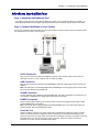
MT2834ZDX-Series
External Data/Fax Modem
User's Guide
User Guide
MT2834ZDX-Series
S000309A Rev. A
Copyright
This publication may not be reproduced, in whole or in part, without prior expressed written permission
from Multi-Tech Systems, Inc. All rights reserved.
Copyright © 2003 Multi-Tech Systems, Inc.
Multi-Tech Systems, Inc. makes no representations or warranties with respect to the contents hereof and
specifically disclaims any implied warranties of merchantability or fitness for any particular purpose.
Furthermore, Multi-Tech Systems, Inc. reserves the right to revise this publication and to make changes
from time to time in the content hereof without obligation of Multi-Tech Systems, Inc. to notify any person
or organization of such revisions or changes.
Revision
A
Date
09/15/03
Description
Initial release of the User Guide for CD publication.
Patents
This device is covered by one or more of the following patents: 6,031,867; 6,012,113; 6,009,082;
5,905,794; 5,864,560; 5,815,567; 5,815,503; 5,812,534; 5,809,068; 5,790,532; 5,764,628; 5,764,627;
5,754,589; 5,724,356; 5,673,268; 5,673,257; 5,644,594; 5,628,030; 5,619,508; 5,617,423; 5,600,649;
5,592,586; 5,577,041; 5,574,725; 5,559,793; 5,546,448; 5,546,395; 5,535,204; 5,500,859; 5,471,470;
5,463,616; 5,453,986; 5,452,289; 5,450,425; D353,598; 5,355,365; 5,309,562; 5,301,274. Other patents
pending.
Trademarks
Multi-Tech and the Multi-Tech logo are trademarks of Multi-Tech Systems, Inc. All other brand and
product names mentioned in this publication are trademarks or registered trademarks of their respective
companies.
Technical Support
Country
U.S. and Canada:
By Email
[email protected]
World Headquarters
Multi-Tech Systems, Inc.
2205 Woodale Drive
Mounds View, Minnesota 55112 U.S.A.
(763) 785-3500 or (800) 328-9717
Fax (763) 785-9874
http://www.multitech.com
By Phone
(800) 972-2439
Table of Contents
Contents
Chapter 1 – Introduction and Installation ................................................................................................. 4
Getting Started........................................................................................................................................... 4
Safety Warnings......................................................................................................................................... 4
We Supply.................................................................................................................................................. 4
Features ..................................................................................................................................................... 4
Modem Installation..................................................................................................................................... 5
Step 1: Attach the Self-Adhesive Feet .................................................................................................. 5
Step 2: Connect the Modem to Your System........................................................................................ 5
Step 3: Install the Modem Driver .......................................................................................................... 6
Step 4: Install Data Communications Software.................................................................................... 6
Removing Your Old Modem from Windows............................................................................................... 6
Chapter 2 – Operation................................................................................................................................. 7
Front Panel ................................................................................................................................................ 7
Chapter 3 – AT Commands, S-Registers and Result Codes .................................................................. 8
AT Commands ........................................................................................................................................... 8
S-Registers .............................................................................................................................................. 18
Register Unit Range Default Description ............................................................................................ 18
Result Codes ........................................................................................................................................... 19
Chapter 4 – Troubleshooting ................................................................................................................... 20
Appendix A – Regulatory Compliance.................................................................................................... 24
Regulatory Compliance............................................................................................................................ 24
Regulatory Requirements for the United States.................................................................................. 24
Regulatory Requirements for Canada................................................................................................. 27
Appendix B – Technical Specifications .................................................................................................. 29
Appendix C – Warranty and Service ....................................................................................................... 30
Index ........................................................................................................................................................... 32
Multi-Tech Systems, Inc. MT2834ZDX User's Guide
3
Chapter 1 – Introduction and Installation
Chapter 1 – Introduction and
Installation
Getting Started
This guide shows you step-by-step how to set up your Multi-Tech MT2834ZDX–Series modem.
For detailed information on how to install, test, and use your modem, see the User Guide, located on the
MT2834ZDX system CD provided with your modem.
Safety Warnings
·
·
·
·
·
·
·
·
Use this product only with UL- and CUL-listed computers (US).
Never install phone wiring during a lightning storm.
Never install a phone jack in a wet location unless the jack is specifically designed for wet locations.
Never touch uninsulated phone wires or terminals unless the phone line has been disconnected at the network
interface.
Use caution when installing or modifying phone lines.
Avoid using a phone during an electrical storm; there is a risk of electrical shock from lightning.
Do not use a phone in the vicinity of a gas leak.
To reduce the risk of fire, use only 26 AWG or larger telephone line cord.
We Supply
·
·
·
·
·
The MT2834ZDX-Series data/fax modem
A DC power supply module
One set of four plastic feet
One telephone cable
A system CD containing modem drivers, the User Guide, Phone Tools (a data communications program), and
Acrobat Reader
Features
The MT2834ZDX automatically adjusts to line conditions and to the capabilities of the modem it connects to, resulting
in the highest transmission speed, the most accurate error correction, and the most efficient data compression
possible for each connection. The MT2834ZDX follows the ITU-T V.34 specification for data rates as high as 28,800
bps over public telephone lines, while the MT2834ZDXb follows the most recent revision of the V.34 specification for
data rates up to 33,600 bps. The MT2834ZDX’s features include:
·
Support of data rates of 33,600 and 31,200 bps (ZDXb only), 28,800, 26,400, 24,000, 21,600, 19,200,
16,800, 14,400, 12,000, 9600, 7200, 4800, 2400, 1200, and 300 bps for communicating with older modems
as well as with other V.34 modems.
·
Automatic fallback to slower speeds in noisy line conditions and fall-forward to faster speeds as conditions
improve.
·
ITU-T V.42 LAP-M and MNP Classes 2–4 error correction.
·
Data transfer rates up to 115,200 bps with V.42bis data compression.
·
Serial port data rates adjustable to 115,200 bps.
·
Autodial, redial, pulse (rotary) and touch-tone dial.
·
Dial tone and busy signal detection for reliable call progress reporting.
·
Compatibility with the standard AT command set used by most communication programs.
·
Nonvolatile memory for storage of custom settings and two telephone numbers.
·
Sends and receives faxes from your computer at 14,400, 9600, 4800, and 2400 bps.
·
Responds to EIA TR29.2 Class 2 fax commands.
Multi-Tech Systems, Inc. MT2834ZDX User's Guide
4
Chapter 1 – Introduction and Installation
Modem Installation
Step 1: Attach the Self-Adhesive Feet
The modem comes with a set of self-adhesive plastic feet, which you can optionally attach to the modem. To
install, simply peel them from their paper strip and press them into the recesses on the bottom of the modem.
Step 2: Connect the Modem to Your System
Turn off your computer. Place the modem in a convenient location, and then connect it to your computer’s serial
port, the phone line, AC power, and your phone.
RS232 Connection
Plug one end of the serial cable into the RS232 connector on the modem, and the other end into a
serial port connector on your computer, such as COM1 or COM2.
LINE Connection
Plug one end of the phone cable into the MT2834ZDX’s LINE jack and the other end into a phone line
wall jack.
Note: The LINE jack is not interchangeable with the PHONE jack. Do not plug the phone into the LINE
jack or the line cable into the PHONE jack.
PHONE Connection
You may optionally plug a telephone into the PHONE jack. This jack is provided as a convenience; you
may also plug a telephone into a duplex jack inserted into your wall jack.
POWER Connection
Plug the power supply module into an AC power outlet or power strip. Plug the power supply’s cable
into the POWER jack on the modem.
Note: Use only the power supply supplied with the MT2834ZDX. Use of any other power supply will
void the warranty and could damage the modem.
Power-On Test
Test the modem by turning it on (a power on/off switch is located on the right side). When you apply
power, the modem performs a diagnostic self-test, indicated by the speed indicators flashing in sequence for a second or two, after which the 28 indicator should light. If this does not happen, check that
the power switch is on, the power supply is solidly connected, and the AC outlet is live. If these
measures do not work, see the Troubleshooting chapter..
Multi-Tech Systems, Inc. MT2834ZDX User's Guide
5
Chapter 1 – Introduction and Installation
Step 3: Install the Modem Driver
If you use Windows 98+, you must install the modem driver, which is installed using the Windows Plug and Play
feature. Follow the four-step procedure below. If you use another operating system, see the Appendix.
1. Make sure your modem is connected properly, and then turn on your computer. Windows should detect
your new modem and open the Install New Modem wizard.
2. Insert the system CD, and then click OK.
3.
4.
Windows installs and configures the modem.
Click Finish to exit.
For Windows NT, the Install New Modem wizard presents one additional prompt before Step 2. At this prompt,
select: Don’t detect my modem; I will select it from a list, and then click Next.
A dialog box with a list of manufacturers and a list of modem models appears. Select your modem. Continue with
Step 2 above.
Note: If Windows cannot identify your modem (for instance, if it identifies your modem as a “Standard Modem”),
click Change. A dialog box with a list of manufacturers and a list of modems appears.
Step 4: Install Data Communications Software
Data communications software is designed to send and receive messages. Multi-Tech includes PhoneTools
communications software with your modem. However, the modem will work with most data communications
software. To install PhoneTools, insert the CD into the CD-ROM drive; click the PhoneTools icon. You will be
asked to choose your language. The software automatically loads onto your PC.
Removing Your Old Modem from
Windows
When a new modem replaces another modem, the old modem installation remains in Windows after you install the
new modem, and the old modem is still selected in HyperTerminal and other Windows applications. Although you can
change the application connection descriptions one at a time, it is easier to force Windows applications to use the
new modem by removing the old modem from Windows.
1. Click the Start button, point to Settings, and click Control Panel.
2. Double-click the Modems icon to open the Modems Properties dialog box.
3.
4.
In the list box, select the old modem.
Click Remove, then click Close.
5.
The next time you dial a HyperTerminal connection, it will select your new modem and ask you to confirm the
selection.
Multi-Tech Systems, Inc. MT2834ZDX User's Guide
6
Chapter 2 – Operation
Chapter 2 – Operation
Front Panel
The MT2834ZDX has ten LED indicators on the front panel that indicate status, configuration, and activity:
Transmit Data. The TD LED lights when the modem is transmitting data to another modem. The state of the LED
matches the TD circuit on pin 2 of the RS-232C/V.24 interface.
Receive Data. The RD LED lights when the modem is receiving data from another modem. The state of the LED
matches that of the RD circuit on pin 3 of the RS-232C/V.24 interface.
Carrier Detect. The CD LED lights when the modem detects a valid carrier signal from another modem. It is on when
the modem is communicating with the other modem and off when the link is broken.
33,600 bps. The 33 LED lights by itself when the modem connects 33,600 bps operation. This LED also lights or
blinks in combination with the 14 LED to indicate speeds between 16,800 and 26,400 bps (see table).
14,400 bps. The 14 LED lights by itself when the modem connects at 14,400 bps. The 14 LED lights or blinks in
combination with the 28 LED to indicate speeds between 16,800 and 26,400 bps. It lights together with the 96 LED to
indicate a speed of 12,000 bps.
9600 bps. The 96 LED lights when the modem connects at 9600 bps. If no speed LED lights, the modem is operating
at less than 9600 bps.
Off-Hook. The OH LED lights when the modem is off-hook, which occurs when the modem is dialing, online, or
answering a call. The LED flashes when the modem pulse-dials.
Terminal Ready. The TR LED lights when a datacomm program initializes the modem. It means the modem is ready
for an outgoing or incoming call. It goes off when the datacomm program disconnects the COM port. When it goes
off, a connected modem will disconnect. The state of the TR LED matches that of the DTR circuit on pin 20 of the RS232C/V.24 interface.
Error Correction (V.42). The EC LED lights continuously when the modem is in error correction mode, and blinks
when compression is activated.
Fax. The FX LED lights when the modem is in fax mode.
Note: When you turn on the MT2834ZDX, the speed lights flash briefly as the modem does a self-test, then the LED
for the default modem baud rate lights. The default rate for the MT2834ZDX is 28,800 bps (33,600 bps for the ZDXb)
unless you select and store another baud rate. After a call, the LEDs for the connection’s baud rate remain lit until
another call is made or the modem is reset. If you connect at a rate under 9600 bps, all speed LEDs remain off after
the connection is broken, even though the modem is still turned on.
Speed Indicator Blink Rates
The 33, 14, and 96 speed indicators light singly or in combination to indicate data rates.
Multi-Tech Systems, Inc. MT2834ZDX User's Guide
7
Chapter 3 – AT Commands, S-Registers, and Results Codes
Chapter 3 – AT Commands, S-Registers
and Result Codes
AT Commands
This section summarizes the AT commands for this modem.
Command:
Values:
Description:
AT Attention Code
n/a
The attention code precedes all command lines except A/, A:, and escape codes.
Command:
Values:
Description:
RETURN Key
n/a
Press the RETURN (ENTER) key to execute most commands.
Command:
Values:
Description:
A Force Answer Mode
n/a
Answer call before final ring.
Command:
Values:
Description:
A/ Repeat Last Command
n/a
Do not precede this command with AT. Do not press RETURN to execute.
Command:
Values:
Description:
A: Continuous Redial
n/a
Redial last number until answered (10 redials in DOC modems). Do not precede this command with
AT or press RETURN to execute.
Command:
Values:
Default:
Description:
&An Answerback
n = 0 or 1
0
&A0 Disables answerback.
&A1 Enables answerback reply to an ID request.
Command:
Values:
Default:
Description:
$An Auto-Reliable Buffering
n = 0 or 1
0
$A0 Discard data received during establishment of a reliable connection.
$A1 Buffer data received during establishment of a reliable connection.
Command:
Values:
Default:
Description:
#An Auto Speed Detection in Answer Mode
n = 0–3
0
#A0 Start at maximum speed and fall back to a lower speed (26400, 24000, 21600, 19200, 16800,
14400, 12000, 9600, 7200, 4800, 2400, 1200, or 300 bps) as line conditions warrant.
#A1 Maximum speed only.
#A2 Start at maximum speed and fall back decrementally to 4800 bps only.
#A3 Start at 2400 bps and fall back to 1200 to 300 bps only.
Command:
Values:
Default:
Description:
&BSn Maximum Reliable Block Size
n = 0 or 1
1
&BS0 Maximum transmit block size of 64 characters.
&BS1 Maximum transmit block size of 256 characters.
Multi-Tech Systems, Inc. MT2834ZDX User's Guide
8
Chapter 3 – AT Commands, S-Registers, and Results Codes
Command:
Values:
Default:
Description:
$BAn Baud Adjust
n = 0 or 1
0
$BA0 Set baud adjust off, speed conversion on. (Serial port speed is independent of modem data
rate.)
$BA1 Set baud adjust on, speed conversion off. (Serial port speed is same as modem data rate.)
Command:
Values:
Default:
Description:
&Cn Carrier Detect Control
n = 0, 1, 2, or 4
1
&C0 Force Carrier Detect high.
&C1 Let Carrier Detect follow carrier signal.
&C2 Let Carrier Detect drop on disconnect, then go high again (for some CBX phone systems).
&C4 Reset modem when Carrier Detect drops.
Command:
Values:
Default:
Description:
&CDn Cleardown at Disconnect
n = 0, 1
0
&CD0 Execute a cleardown at disconnect.
&CD1 Do not execute a cleardown at disconnect.
Command:
Values:
Default:
Description:
Ds Dial
s = dial string (phone number and dial modifiers)
none
Dial telephone number s, where s may include up to 60 digits and T, P, R, comma, colon, and
semicolon characters.
Command:
Values:
DsNd Store Telephone Number
s = dial string (phone number and dial modifiers)
d = 0 or 1
none
To store, enter D followed by dial string s, then N followed by directory number d.
ATDT9,5551212N1.
Default:
Description:
Example:
Command:
Values:
Default:
Description:
&Dn Data Terminal Ready Control
n = 0–3
2
&D0 Modem ignores DTR signal.
&D1 When DTR drops, the modem hangs up. While DTR is low, the modem accepts commands
but will not dial or auto-answer until DTR goes high again.
&D2 Same as &D1.
&D3 When DTR drops, the modem hangs up and resets as if an ATZ command were issued.
Command:
Values:
Default:
Description:
$Dn DTR Dialing
n = 0 or 1
0
$D0 Do not dial when DTR goes high.
$D1 Dial stored number N0 when DTR goes high.
Command:
Values:
Default:
Description:
%DCn AT Command Control
n = 0 or 1
0
%DC0 The modem responds to AT commands.
%DC1 The modem ignores AT commands.
Note: The modem will respond to AT%DC for 10 seconds after power-up.
Command:
Values:
Default:
Description:
%DFn Format Line Probe Data
n = 0 or 1
0
%DF0 Display data in graph format. Y axis is gain shown in dBm.
%DF1 Display data in table format. Gain is shown numerically in dBm at 75Hz increments from
150Hz to 3750Hz.
Multi-Tech Systems, Inc. MT2834ZDX User's Guide
9
Chapter 3 – AT Commands, S-Registers, and Results Codes
Command:
Values:
Default:
Description:
%DPn Read Line Probe Data
n = 0 or 1
0
%DP0 Do not read and store line probe information from DSP during handshake.
%DP1 Read and store line probe information from DSP during handshake.
Command:
Values:
Default:
Description:
>DTn DTMF Detection
n = 0 or 1
0
>DT0 The modem will not detect DTMF tones.
>DT1 The modem will detect and report DTMF tones when it is off-hook.
Command:
Values:
Default:
Description:
En Echo Command Mode Characters
n = 0 or 1
1
E0 Do not echo keyboard input to the terminal.
E1 Do echo keyboard input to the terminal.
Command:
Values:
Default:
Description:
&En V.42 Error Correction Modes
n = 0, 1, or 2
1
&E0 V.42 non-error correction mode (V.42 disabled).
&E1 V.42 auto-reliable mode.
&E2 V.42 reliable mode (V.42 enabled).
Command:
Values:
Defaults:
Description:
&En Modem-Initiated Flow Control
n = 3, 4, or 5
4
&E3 Flow control disabled.
&E4 CTS/RTS hardware flow control.
&E5 XON/XOFF software flow control.
Command:
Values:
Defaults:
Description:
&En XON/XOFF Pass-Through
n = 6 or 7
6
&E6 Respond to and discard XON/XOFF characters when &E5 is selected.
&E7 Respond to and pass through XON/XOFF characters when &E5 is selected.
Command:
Values:
Default:
Description:
&En Hewlett Packard ENQ/ACK Pacing
n = 8 or 9
8
&E8 Ignore ENQ/ACK pacing characters.
&E9 Respond to ENQ/ACK pacing characters.
Command:
Values:
Default:
Description:
&En Non-Error Correction Mode Flow Control
n = 10 or 11
10
&E10 Disable non-error correction mode flow control.
&E11 Enable non-error correction mode flow control.
Command:
Values:
Default:
Description:
&En Pacing (Computer-Initiated Flow Control)
n = 12 or 13
13
&E12 Pacing disabled.
&E13 Pacing enabled.
Command:
Values:
Default:
Description:
&En Data Compression
n = 14 or 15
15
&E14 Data compression disabled.
&E15 Data compression enabled.
Multi-Tech Systems, Inc. MT2834ZDX User's Guide
10
Chapter 3 – AT Commands, S-Registers, and Results Codes
Command:
Values:
Default:
Description:
$En V.42 Error Correction at 300 bps
n = 0 or 1
0
$E0 V.42 error correction at 300 bps disabled.
$E1 V.42 error correction at 300 bps enabled.
Command:
Values:
Default:
Description:
$EBn Asynchronous Word Length
n = 0 or 1
0
$EB0 10-bit mode enabled.
$EB1 11-bit mode enabled.
Command:
Values:
Defaults:
Description:
%En Escape Sequence Options
n = 0–5
1 and 4
%E0 Modem won’t escape.
%E1 +++AT<CR> method.
%E2 <BREAK>AT<CR> method.
%E3 Both +++AT<CR> and <BREAK>AT<CR> methods.
%E4 No OK response to +++AT<CR>.
%E5 OK response to +++AT<CR>.
Command:
Values:
Default:
Description:
&Fn Load Default Configurations
n = 0, 8, or 9
8
&F0 Load factory default values from ROM if &F8 was previously stored; load user default values
from non-volatile memory if &F9 was previously stored.
&F8 Read factory default values when &F is issued (effective only if you store &F8 using &W0).
&F9 Read values stored in non-volatile memory when &F is issued (effective only if you store &F9
using &W0).
Command:
Values:
Default:
Description:
$Fn Enable/Disable Auto-Reliable Fallback Character
n = 0 or 1
0
$F0 Do not fall back to non-error correction mode connect if <CR> is received during handshake.
$F1 Fall back to non-error correction mode connect if <CR> is received during handshake.
Command:
Values:
Default:
Description:
%Fn Echo Frequency Canceller Offset Compensation
n = 0 or 1
0
%F0 Disable echo canceller frequency offset compensation.
%F1 Enable echo canceller frequency offset compensation.
Command:
Values:
Default:
Description:
#Fn Fallback Modes When Online
n = 0, 1, or 2
2
#F0 No fallback when on line.
#F1 Fallback decrementally from maximum speed to 4800 bps as line conditions deteriorate.
#F2 Fallback decrementally to 4800 bps; fall forward when line conditions improve.
Command:
Values:
Default:
Description:
&Gn Guard Tones
n = 0, 1, or 2
0
&G0 Turn off ITU-T guard tones.
&G1 Turn on ITU-T 550 Hz guard tone.
&G2 Turn on ITU-T 1800 Hz guard tone.
Note: The ZDXK is locked to the ITU-T 1800 Hz guard tone (&G2).
Command:
Values:
Default:
Description:
Hn On Hook/Off Hook
n = 0 or 1
None
H0 Go on hook (hang up).
H1 Go off hook.
Multi-Tech Systems, Inc. MT2834ZDX User's Guide
11
Chapter 3 – AT Commands, S-Registers, and Results Codes
Command:
Values:
Default:
Description:
$Hn Help Screens
n = 1, 2, or 3
None
$H1 Display Help Screen #1.
$H2 Display Help Screen #2.
$H3 Display Help Screen #3.
Command:
Values:
Default:
Description:
In Inquire Product Codes
n = 0, 1, or 2
None
I0 Display modem ID number.
I1 Display firmware version number.
I2 Display modem description.
Command:
Values:
Default:
Description:
$Jn Display Parity Bit
n = 0, 1
0
The $J command allows the parity bit to be seen when XON/OFF flow control is enabled (see the
&E command.)
$J0 disables the display of the parity bit to be seen when XON/XOFF flow control is enabled.
$J1 enables the display of the parity bit to be seen when XON/XOFF flow control is enabled.
Command:
Values:
Default:
Description:
Ln List Commands
n = 0, 5–8
None
L List stored telephone numbers.
L5 List current operating parameters.
L6 List current S-register values.
L7 List additional current operating parameters.
L8 List DSP code version number, processor speed, and online diagnostic parameters.
L9 List signal strength information.
L10 List signal to noise ratio information (SNR).
L11 List noise information.
Note: For L9, L10, and L11, you must first type +++AT<CR> (online escape command while
maintaining command mode), then type the command prefixed by an AT (e.g., ATL10).
Command:
Values:
Default:
Description:
#Ln
V.42 Mode Selection in Originate Mode
n = 0, 1, 2, or 3
0
#L0 Modems negotiate V.42 mode.
#L1 MNP on & LAP-M off.
#L2 LAP-M on & MNP off.
#L3 Disable detection phase and go directly to LAP-M.
Command:
Values:
Default:
Description:
Mn Modem Speaker Control
n = 0, 1, 2, or 3
1
M0 Speaker always off.
M1 Speaker on until carrier signal detected.
M2 Speaker always on.
M3 Speaker on during dialing, off during handshaking.
Multi-Tech Systems, Inc. MT2834ZDX User's Guide
12
Chapter 3 – AT Commands, S-Registers, and Results Codes
Command:
Values:
Default:
Description:
$MBn Modem Baud Rate
n = speed
28800 (ZDX) or 33600 (ZDXb)
$MB300 Originate call at 300 bps.
$MB1200 Originate call at 1200 bps.
$MB2400 Originate call at 2400 bps.
$MB4800 Originate call at 4800 bps.
$MB7200 Originate call at 7200 bps.
$MB9600 Originate call at 9600 bps.
$MB14400 Originate call at 14,400 bps.
$MB16800 Originate call at 16, 800 bps.
$MB19200 Originate call at 19,200 bps.
$MB28800 Originate call at 28,800 bps.
$MB33600 Originate call at 33,600 bps (ZDXb only).
Command:
Values:
Default:
Description:
Nd Dial a Stored Number
d = 0 or 1
None
Dial stored telephone number d.
Command:
Values:
Default:
Description:
NdNe. .. Number Linking
d = 0 or 1; e = 1 or 0
None
Dial stored number d; if it is busy, dial stored number e.
Command:
Values:
Description:
O Go Back Online
n/a
Return to online mode after you have used an escape sequence to go from online mode to
command mode.
Command:
Values:
Default:
Description:
P Pulse Dial
n/a
Yes
The modem pulse-dials numbers that follow P in the dialing command.
Command:
Values:
Default:
Description:
&Pn Set Pulse Dial Ratios
n = 0 or 1
0
&P0 60:40 break/make pulse ratio.
&P1 67:33 break/make pulse ratio.
Note: The ZDXK is locked to a 67:33 pulse ratio (&P1).
Command:
Values:
Default:
Description:
Qn Result Codes Enable/Disable
n = 0, 1, or 2
0
Q0 Enable result codes.
Q1 Disable result codes (quiet).
Q2 Enable no-response answer mode, which leaves originate mode intelligent while turning off
answer mode responses and echo.
Command:
Values:
Default:
Description:
&Qn Multi-Tech or Standard Result Codes
n = 0 or 1
0
&Q0 Multi-Tech responses with modifiers.
&Q1 Standard AT responses with no modifiers.
Command:
Values:
Default:
Description:
Rn Reverse Originate/Answer Modes
n = 0 or 1
0
R0 Modem will not reverse modes.
R1 Modem will reverse modes when R is added to the dial string.
Multi-Tech Systems, Inc. MT2834ZDX User's Guide
13
Chapter 3 – AT Commands, S-Registers, and Results Codes
Command:
Values:
Default:
Description:
&Rn Clear to Send Control
n = 0, 1, or 2
1
&R0 Let CTS state follow RTS state when on line.
&R1 Force CTS high (on).
&R2 Let CTS drop on disconnect for time set by S24, then go high again.
Command:
Values:
Default:
Description:
&RAn Asymmetrical Bit Rate
n = 0 or 1
0
&RA0 Enable asymmetrical bit rate in V.34 mode.
&RA1 Disable asymmetrical bit rate in V.34 mode.
Command:
Values:
Default:
Description:
&RDn Square Wave Ring Detect
n = 0 or 1
1
&RD0 Modem detects only sine wave rings.
&RD1 Modem detects both sine and square wave rings.
Command:
Values:
Default:
Description:
&RFn CTS/RTS Interaction Control
n = 0 or 1
1
&RF0 Let CTS follow RTS.
&RF1 Let CTS act independently (use with &R).
Command:
Values:
Description:
&RN Rate Negotiation
n/a
Forces the modem to perform a rate renegotiation while on line. You must escape to command
mode to issue this command.
Command:
Values:
Description:
&RP Immediate Line Probe
n/a
Initiates a retrain that makes the processor read line probe information if %DP1 is selected. Valid
only when on line in V.34 mode.
Command:
Values:
Description:
&RR Immediate Retrain
n/a
Forces the modem to perform an immediate retrain while on line. You must escape to command
mode to issue this command.
Command:
Values:
Default:
Description:
$Rn Retransmit Count
n = 0 or 1
0
$R0 Disconnect after 50 retransmits of a data block.
$R1 Do not disconnect after 50 retransmits.
Command:
Values:
Default:
Description:
Sr=n Set Register Value
r = S-register number; n varies
None
Set value of register S r to value of n, where n is entered in decimal format.
Command:
Values:
Default:
Description:
Sr? Read Register Value
r = S-register number
None
Read value of register S r and display value in 3- digit decimal form.
Command:
Values:
Default:
Description:
&Sn Data Set Ready Control
n = 0, 1, or 2
1
&S0 Force DSR high (on).
&S1 Let DSR follow CD.
&S2 DSR drops on disconnect, then goes high again. (Used by some CBX phone systems.)
Multi-Tech Systems, Inc. MT2834ZDX User's Guide
14
Chapter 3 – AT Commands, S-Registers, and Results Codes
Command:
Values:
Default:
Description:
&SFn DSR/CD Interaction Control
n = 0 or 1
0
&SF0 Select DSR to follow CD.
&SF1 Select DSR to be independent.
Command:
Values:
Default:
Description:
$SBn Serial Port Baud Rate
n = speed
57600
$SB300 Set serial port to 300 bps.
$SB1200 Set serial port to 1200 bps.
$SB2400 Set serial port to 2400 bps.
$SB4800 Set serial port to 4800 bps.
$SB9600 Set serial port to 9600 bps.
$SB19200 Set serial port to 19200 bps.
$SB38400 Set serial port to 38400 bps.
$SB57600 Set serial port to 57600 bps.
$SB115200 Set serial port to 115200 bps.
Note: Baud adjust must be off ($BA0) to enable fixed baud rate.
Command:
Values:
Default:
Description:
T Tone-Dial
n/a
P command
Modem will tone-dial numbers following a T in the dialing command.
Command:
Values:
Default:
Description:
&Tn Respond to Remote Digital Loopback Signal
n = 4 or 5
5
&T4 Enable response to remote digital loopback signal.
&T5 Disable response to remote digital loopback signal.
Command:
Values:
Default:
Description:
#Tn Trellis-Coded Modulation
n = 0 or 1
1
#T0 Disable trellis-coded modulation.
#T1 Enable trellis-coded modulation.
Command:
Values:
Default:
Description:
Un Loopback Test Modes
n = 0, 1, 2, or 3
None
U0 Enable local nalog loopback originate mode.
U1 Enable local analog loopback answer mode.
U2 Enable remote digital loopback mode.
U3 Enable local digital loopback mode.
Command:
Values:
Default:
Description:
Vn Result Codes (Verbose/Terse)
n = 0 or 1
1
V0 Result codes sent as digits (terse response).
V1 Result codes sent as words (verbose response).
Command:
Values:
Default:
Description:
#Vn V.32terbo Handshake Tones
n = 0 or 1
1
#V0 Include V.32terbo tones in handshake.
#V1 Exclude V.32terbo tones from handshake.
Command:
Values:
Description:
W Wait for New Dial Tone
n/a
Inserted in dialing command, causes modem to wait for a new dial tone. (X2 or X4 must be
selected.)
Multi-Tech Systems, Inc. MT2834ZDX User's Guide
15
Chapter 3 – AT Commands, S-Registers, and Results Codes
Command:
Values:
Default:
Description:
&Wn Store Configuration
n = 0 or 1
1
&W0 Store current settings in NVRAM; load them at power-on or following the ATZ command
instead of loading the factory defaults from ROM.
W1 Clear user default settings from NVRAM.
Command:
Values:
Default:
Description:
Xn Result Codes and Call Progress Selection
n = 0–4
0
X0 Basic result codes ( CONNECT only); does not look for dial tone or busy signal.
X1 Extended result codes ( CONNECT 28800, CONNECT 33600, etc.); does not look for dial tone
or busy signal.
X2 Extended result codes with NO DIALTONE; does not look for busy signal.
X3 Extended result codes with BUSY; does not look for dial tone.
X4 Extended result codes with NO DIALTONE and BUSY.
Command:
Values:
Default:
Description:
#Xn Number of XOFF Characters Sent
n = 0 or 1
0
#X0 Single XOFF character sent after buffer is full.
#X1 Multiple XOFF characters sent (one for every character received after buffer is full).
Command:
Values:
Default:
Description:
Yn Long Space Disconnect
n = 0 or 1
0
Y0 Disable sending or responding to long space break signal on disconnect.
Y1 Enable sending or responding to long space break signal on disconnect. (Both modems must
have Y1 set.)
Command:
Values:
Description:
Z Modem Reset
n/a
Reset modem to default values. Defaults come from user NVRAM if &W0 is set, from factory ROM
if &W1 is set.
Command:
Values:
Description:
, Dialing Pause
n/a
Placed in dialing command, comma causes dialing pause for time set by S8.
Command:
Values:
Description:
: Continuous Redial
n/a
Placed at end of dial command, a colon causes continuous redial of a number (10 in DOC
modems) until answered. Not used in ZDXK or ZDXI modems.
Command:
Values:
Description:
; Return to Command Mode
n/a
Placed at end of dial command, a semicolon causes an immediate return to command mode after
dialing.
Command:
Values:
Description:
! Flash On-Hook
n/a
Placed in dial command, exclamation point causes modem to flash on-hook.
Command:
Values:
Description:
@ Quiet Answer
n/a
Placed in dial command, @ causes modem to wait for a ringback, then 5 seconds of silence, before
processing next part of command.
Command:
Values:
Description:
$ Call Card Tone Detect
n/a
Placed in dial command, causes modem to wait for a call card tone before processing next part of
command (such as a call card number).
Multi-Tech Systems, Inc. MT2834ZDX User's Guide
16
Chapter 3 – AT Commands, S-Registers, and Results Codes
Command:
Values:
Description:
%%%AT<CR> Remote Configuration Escape Sequence
n/a
Initiates remote configuration mode while online with remote modem. The remote configuration
escape character (%) is defined in register S13.
Command:
Values:
Description:
+++AT<CR> Escape Code
n/a
Puts modem in command mode (and optionally issues a command) while remaining on line.
Enter +++AT, up to ten command characters (or as defined by S34), and a RETURN. Used mostly
to issue hang-up command: +++ATH<CR>.
Command:
Values:
Description:
<BREAK>AT<CR> Escape Sequence
n/a
Alternate escape method. Puts modem in command mode while remaining on line. Send a
<BREAK> signal followed by AT, up to sixty command characters, and a RETURN. You must set
the modem to %E2 or %E3 before you can use this escape method.
Multi-Tech Systems, Inc. MT2834ZDX User's Guide
17
Chapter 3 – AT Commands, S-Registers, and Results Codes
S-Registers
Certain modem values, or parameters, are stored in memory locations called S-registers. Use the S command to
read or to alter the contents of S-Registers (see previous section).
Register Unit Range Default Description
Register
Unit
S0
1 ring
S1
S2
S3
S4
S5
S6
1 ring
decimal
decimal
decimal
decimal
1 sec.
S7
S8
1 sec.
1 sec.
S9
100 ms
S10
100 ms
S11
1 ms
S13
decimal
S17
10 ms
S24
50 ms
S25
100 ms
S30
1 min.
S32
100 ms
S34
S36
1 char
1 sec.
S37
S43
1 sec.
decimal
S48
decimal
Range Default Description
Sets the number of rings until the modem answers. ATS0=0
disables autoanswer completely.
0–255
0
Counts the rings that have occurred.
0–127
43(+)
Sets ASCII code for the escape code character.
0–127
13 (^M) Sets ASCII code for the RETURN character.
0–127
10 (^J) Sets ASCII code for the LINE FEED character.
0–127
8 (^H) Sets ASCII code for the BACKSPACE character.
2–255
2
Sets the time the modem will wait for a dial tone before aborting a
call.
1–255
45
Sets the time the modem.
0–255
2
Sets the length of a pause caused by a comma character in a
dialing command.
1–255
6
Sets delay between when the modem detects a valid carrier
signal and when it turns on its CD circuit.
1–254
7
Sets how long a carrier signal must be lost before the modem
disconnects. S10=255 causes the modem to not disconnect with
loss of carrier.
1–255
70
Sets spacing and duration of dialing tones. Recommended
minimum is 50 ms.
0, 1–127 37 (%) Sets ASCII code for remote configuration escape character.
S13=0 disables remote configuration.
1–255
25
Sets the length of the break time (space) sent to the local PC
when the modem receives a remote break.
0–255
20
Sets the time the DSR, CTS, and CD signals drop before going
high again. Used for some PBX and CBX phone systems.
0, 1–255 0
Sets the time the DTR signal must be dropped before the modem
disconnects. The 0 default equals 50 ms.
0, 1–255 0
Sets how long the modem waits after the last character is
received or transmitted before it disconnects. The 0 default
disables the timer.
0–255
20
Sets the time the modem will wait for a RETURN to be entered
during escape sequence execution.
Sets the number of command characters allowed after +++AT.
0–60
10
Sets the time between DTR inactive and modem offhook. S36=0
0, 1-255 5
disables DTR busy-out.
0-255
5
Sets the time between DTR active and modem on-hook.
28, 26,
0
Sets fixed V.34 connect speed. 28 = 28800 bps; 26 = 26400 bps;
24, 21,
48 = 4800 bps. 0 default disables this feature.
19, 16,
14, 12,
96, or 48
33, 31,
0
Sets maximum V.34 connect speed. 33 = 33600 bps; 31 = 31200
28, 26,
bps;…48 = 4800 bps. 0 default disables feature (same as
S48=33).
24, 21,
19, 16,
14, 12,
96, or 48
0, 1–255 1
Multi-Tech Systems, Inc. MT2834ZDX User's Guide
18
Chapter 3 – AT Commands, S-Registers, and Results Codes
Result Codes
In command mode the MT2834ZDX can send responses, or result codes, to your computer. Result codes are used
by communications programs and can also appear on your monitor.
AT&Q0 selects Multi-Tech result codes with RELIABLE, LAPM, and COMPRESSED modifiers (default).
AT&Q1 selects standard AT result codes without modifiers.
&Q0 Multi-Tech Result Codes &Q1 Standard Result Codes Description
Terse
0
1
2
3
Verbose
OK
CONNECT
RING
NO CARRIER
Terse
0
1
2
3
Verbose
OK
CONNECT
RING
NO CARRIER
Command executed without error
Modem has detected carrier and gone online
Modem has detected ring from incoming call
No carrier has been signal detected within
allowed time
4
ERROR
4
ERROR
Error in command line (too many
characters or invalid characters
5*
CONNECT 1200
5
CONNECT 1200
Modem has detected carrier at 2400bps
and gone online
6
NO DIALTONE
6
NO DIALTONE
No dial tone detected
7
BUSY
7
BUSY
A busy signal detected
8
NO ANSWER
8
NO ANSWER
Remote system did not answer
9
CONNECT 2400
Modem had detected carrier at 2400 bps
and gone online
10
CONNECT 2400
Modem had detected carrier at 2400 bps
and gone online
11 *
CONNECT 4800
11
CONNECT 4800
Modem had detected carrier at 4800 bps
and gone online
12 *
CONNECT 9600
12
CONNECT 9600
Modem had detected carrier at 9600 bps
and gone online
13
CONNECT 12000
13
CONNECT 12000
Modem had detected carrier at 12000 bps
and gone online
13 *
CONNECT 14400
13
CONNECT 14400
Modem had detected carrier at 14400 bps
and gone online
16
CONNECT 16800
16
CONNECT 16800
Modem had detected carrier at 16800 bps
and gone online
19 *
CONNECT 19200
19
CONNECT 19200
Modem had detected carrier at 19200 bps
and gone online
21 *
CONNECT 21600
21
CONNECT 21600
Modem had detected carrier at 21600 bps
and gone online
24 *
CONNECT 24000
24
CONNECT 24000
Modem had detected carrier at 24000 bps
and gone online
26 *
CONNECT 26400
26
CONNECT 26400
Modem had detected carrier at 26400 bps
and gone online
28 *
CONNECT 28800
28
CONNECT 28800
Modem had detected carrier at 28800 bps
and gone online
31 *
CONNECT 31200
31
CONNECT 31200
Modem had detected carrier at 31200 bps
and gone online
33 *
CONNECT 33600
32
CONNECT 33600
Modem had detected carrier at 33600 bps
and gone online
*With error correction on, RELIABLE (or R) or LAPM (or L) is added to these result codes. With data compression on,
COMPRESSED (or C) is added.
Multi-Tech Systems, Inc. MT2834ZDX User's Guide
19
Chapter 4 – Troubleshooting
Chapter 4 – Troubleshooting
Your MultiModemZDX modem was thoroughly tested at the factory before it was shipped. If you are unable to make a
successful connection, or if you experience data loss or garbled characters during your connection, it is possible that
the modem is defective. However, it is more likely that the source of your problem lies elsewhere. The following
symptoms are typical of problems you may encounter:
·
None of the LEDs light when the modem is on.
·
The modem does not respond to commands.
·
The modem dials but cannot connect.
·
The modem disconnects while online.
·
The modem cannot connect when answering.
·
File transfer is slower than it should be.
·
Data is being lost.
·
There are garbage characters on the monitor.
·
Fax and data programs can’t run at the same time.
If you experience problems, please check the following possibilities before calling Technical Support
(see Appendix C).
None of the LEDs Light When the Modem Is On
When you turn on the ZDX, the LED indicators on the front panel should flash briefly as the modem runs a selftest. If the LEDs remain off, the modem is probably not receiving power.
·
Make sure the modem’s power switch is on, especially if you normally turn on the modem by turning on a
power strip.
·
If the power supply is plugged into a power strip, make sure the power strip is plugged in and its power
switch is on. Make sure the power supply module is firmly connected to the modem and to the wall outlet or
power strip.
·
If the power strip is on and the modem switch is on, try moving the modem power supply to another outlet on
the power strip.
·
Test that the outlet is live by plugging a lamp into it.
·
The modem or power supply may be defective. If you have another Multi-Tech modem, try swapping
modems. If the problem goes away, the first modem or power supply may be defective. Call Technical
Support for assistance.
CAUTION: Do not under any circumstance replace the power supply module with one designed for another
product, as it can damage the modem and void your warranty.
The Modem Does Not Respond to Commands
·
·
·
·
·
Make sure the modem is plugged in and turned on. (See “None of the Indicators Light when the Modem Is
On.”)
Make sure you are issuing the modem commands from a data communication program, either manually in
terminal mode or automatically by configuring the program. (You cannot send commands to the modem
from the DOS prompt.)
Make sure you are in terminal mode in your data communication program, then type AT and press ENTER.
If you get an OK response, your connections are good, and the problem likely is in the connection setup in
your communication program.
Try resetting your modem by turning it off and on.
If you don’t get an OK, the problem may still be in the communication program. Make sure you have done
whatever is necessary in your software to make a port connection. Not all communication programs connect
to the COM port automatically. Some connect when the software loads and remain connected until the
program terminates. Others can disconnect without exiting the program. The modem’s TR indicator lights to
show that the software has taken control of the modem through the COM port.
Multi-Tech Systems, Inc. MT2834ZDX User's Guide
20
Chapter 4 – Troubleshooting
·
·
·
·
·
·
·
Your communication program settings might not match the physical port the modem is connected to. The
serial cable might be plugged into the wrong connector—check your computer documentation to make sure.
Or you might have selected a COM port in the program other than the one the modem is physically
connected to—compare the settings in the program to the physical connection.
If the modem is on, the cable is plugged into the correct port, the communication program is configured
correctly, and you still don’t get an OK, the fault might be in the serial cable. Make sure it is firmly connected
at both ends.
Is this the first time you have used the cable? If so, it may not be wired correctly. Check the cable
description on the package to make sure the cable is the right one for your computer.
Peripheral expansion cards, such as sound and game cards, can include a serial port preconfigured as
COM1 or COM2. The extra serial port, or the card itself, may use the same COM port, memory address, or
interrupt request (IRQ) as your communications port. Be sure to disable any unused ports.
If you use Windows 98, right-click on My Computer, select Properties from the menu, click on the Device
Manager tab, double-click on Ports, then double-click the communications port your modem is connected
to. In the port’s Properties dialog box, click the Resources tab to see the port’s input/output range and
interrupt request. If another device is using the same address range or IRQ, it will appear in the Conflicting
Device List. Uncheck Use automatic settings to change the port’s settings so they do not conflict with the
other device, or select the port the conflicting device is on, and change it instead. If you need to open your
computer to change switches or jumpers on the conflicting device; refer to the documentation for the device.
If you use Windows NT 4.0, select in turn Start, Programs, Administrative Tools (Common), and
Windows NT Diagnostics. In the Windows NT Diagnostics dialog box, click on the Resources tab to see
address and IRQ assignments.
The serial port might be defective. If you have another serial port, install the modem on it, change the COM
port setting in your software, and try again.
The modem might be defective. If you have another Multi-Tech modem, try swapping modems. If the
problem goes away, the first modem is possibly defective. Call Technical Support for assistance (see
Appendix C).
The Modem Dials But Cannot Connect
There can be several reasons the ZDX fails to make a connection.
Possibilities include:
·
Lack of a physical connection to the telephone line.
·
A wrong dial tone.
·
A busy signal.
·
A wrong number.
·
No modem at the other end.
·
A faulty modem, computer, or software at the other end.
·
Incompatibility between modems.
You can narrow the list of possibilities by using extended result codes. Extended result codes are enabled by
default. If they have been disabled, include V1X4 in the modem’s initialization string, or in terminal mode enter
ATV1X4 and press ENTER. When you dial again, the modem will report the call’s progress.
·
If the modem reports NO DIALTONE, check that the modem’s telephone line cable is connected to both the
modem’s LINE jack (not the PHONE jack) and the telephone wall jack. If the cable looks secure, try
replacing it. If that doesn’t work, the problem might be in your building’s telephone installation. To test the
building installation, plug a telephone into your modem’s telephone wall jack and listen for a dial tone. If you
hear a dial tone, your modem might be installed behind a company phone system (PBX) with an internal dial
tone that sounds different from the normal dial tone. In that case, the modem might not recognize the dial
tone and might treat it as an error. Make sure your modem’s square wave ring detection is turned on
(&RD1). Check the PBX manual to see if you can change the internal dial tone; if you can’t, change your
modem’s initialization string to replace X4 with X3, which will cause the modem to ignore dial tones.
·
If the modem reports BUSY, the other number might be busy, in which case you should try again later, or it
might indicate that you have failed to add a 9, prefix to the phone number if you must dial 9 for an outside
line. If you must dial 9 to get an outside line, the easiest way to dial it automatically is to include it in the
modem’s dial prefix, e.g., ATDT9,. Note the comma, which inserts a pause before the number is dialed. By
inserting 9, into the dial prefix, you do not have to include it in each directory entry. To change the dial prefix
in Windows 95 HyperTerminal, select Connect from the Call menu, click Dialing Properties, and type 9 in
the local and long distance boxes in How I dial from this location.
·
If the modem reports NO ANSWER, the other system has failed to go off-hook, or you might have dialed a
wrong number. Check the number.
Multi-Tech Systems, Inc. MT2834ZDX User's Guide
21
Chapter 4 – Troubleshooting
·
If the modem reports NO CARRIER, the phone was answered at the other end, but no connection was
made. You might have dialed a wrong number, and a person answered instead of a computer, or you might
have dialed the correct number but the other computer or software was turned off or faulty. Check the
number and try again, or try calling another system to make sure your modem is working. Also, try calling
the number on your telephone. If you hear harsh sounds, then a modem is answering the call, and the
modems might be having problems negotiating because of modem incompatibilities or line noise. Try
connecting at a lower speed.
The Modem Disconnects While Online
·
If you have Call Waiting on the same line as your modem, it can interrupt your connection each time
someone tries to call you. If you have Call Waiting, disable it before each call. In most telephone areas in
North America, you can disable Call Waiting by preceding the telephone number with *70 (check with your
local telephone company). You can automatically disable Call Waiting by including the disabling code in the
modem’s dial prefix (e.g., ATDT*70,—note the comma, which inserts a pause before the number is dialed).
To change the dial prefix in Windows Terminal, select Settings | Modem Commands. To change it in
HyperTerminal, select Connect from the Call menu, click Dialing Properties, check This location has Call
Waiting, and select the correct code for your phone service.
·
If you have extension phones on the same line as your modem, you or someone else can interrupt the
connection by picking up another phone. If this is a frequent problem, disconnect the extension phones
before using the modem, or order a separate line for the modem.
·
Check for loose connections between the modem and the computer, the telephone jack, and AC power.
·
You might have had a poor connection because of line conditions or the problem might have originated on
the other end of the line. Try again.
The Modem Cannot Connect When Answering
·
Autoanswer might be disabled. Turn on autoanswer in your datacomm program or send the command
ATS0=1 to your modem in terminal mode.
File Transfer Is Slower Than It Should Be
·
You might have an older UART. For best throughput, install a 16550AFN UART or a Multi-Tech ISI serial
port card.
·
If you are using a slow transfer protocol, such as Xmodem or Kermit, try Zmodem or Ymodem/G instead.
·
Is your line noisy? If there is static on your line, the modem has to resend many blocks of data to insure
accuracy. You must have a clean line for maximum speed.
·
Are you downloading a compressed file with MNP 5 hardware compression enabled? Since hardware data
compression cannot compress a file already compressed by an archiving program, the transfer can be
marginally slower with data compression enabled than with it disabled.
·
Try entering the L8 (List Online Diagnostics) command in online mode, making a screen print of the
diagnostics listing, and checking for parameters that may be unacceptable (number of retrains, round trip
delay, etc.).
Data Is Being Lost
·
If you are using data compression and a high speed serial port, set the serial port baud rate to four times the
data rate.
·
Your UART might not be reliable at serial port speeds over 9600 bps or 19,200 bps. Turn off data
compression, reset your serial port speed to a lower rate, or replace your serial port with a faster one.
·
Make sure the flow control method you selected in software matches the method selected in the modem. If
you are using the modem with a Macintosh, you might have the wrong cable for hardware flow control.
·
Try entering the L8 (List Online Diagnostics) command in online mode, making a screen print of the
diagnostics listing, and checking for parameters that may be unacceptable (number of retrains, round trip
delay, etc.).
Multi-Tech Systems, Inc. MT2834ZDX User's Guide
22
Chapter 4 – Troubleshooting
There Are Garbage Characters on the Monitor
·
Your computer and the remote computer might be set to different word lengths, stop bits, or parities. If you
have connected at 8-N-1, try changing to 7-E-1, or vice-versa, using your communication software.
·
4 You might be experiencing line noise. Enable error correction, if it is disabled, or hang up and call again;
you might get a better connection the next time.
·
At speeds above 2400 bps, the remote modem might not use the same transmission or error correction
standards as your modem. Try connecting at a slower speed or disabling error correction. (With no error
correction, however, line noise can cause garbage characters.)
·
Try entering the L8 (List Online Diagnostics) command in online mode, making a screen print of the
diagnostics listing, and checking for parameters that may be unacceptable (number of retrains, round trip
delay, etc.).
Fax and Data Programs Can’t Run at the Same Time
·
Communications devices can be accessed by only one application at a time. In Windows 95, 98, and NT
4.0, you can have separate data and fax communication applications open at the same time, but they cannot
use the same modem at the same time.
Multi-Tech Systems, Inc. MT2834ZDX User's Guide
23
Appendix A – Regulatory Compliance
Appendix A – Regulatory Compliance
Regulatory Compliance
Regulatory Requirements for the United States
47 CFR Part 15 Regulation
This equipment has been tested and found to comply with the limits for a Class B digital device, pursuant to
47 CFR Part 15 regulations. The stated limits in this regulation are designed to provide reasonable
protection against harmful interference in a residential installation. This equipment generates, uses, and can
radiate radio frequency energy, and if not installed and used in accordance with the instructions, may cause
harmful interference to radio communications. However, there is no guarantee that interference will not
occur in a particular installation. If this equipment does cause harmful interference to radio or television
reception, which can be determined by turning the equipment off and on, the user is encouraged to try to
correct the interference by one or more of the following measures:
·
·
·
·
Reorient or relocate the receiving antenna.
Increase the separation between the equipment and receiver.
Plug the equipment into an outlet on a circuit different from that to which the receiver is connected.
Consult the dealer or an experienced radio/TV technician for help.
This device complies with Part 15 of the CFR 47 rules. Operation of this device is subject to the following
conditions: (1) This device may not cause harmful interference, and (2) this device must accept any
interference that may cause undesired operation.
WARNING – Changes or modifications to this unit not expressly approved by the party responsible for
compliance could void the user’s authority to operate the equipment.
Multi-Tech Systems, Inc. MT2834ZDX User's Guide
24
Appendix A – Regulatory Compliance
47 CFR Part 68 Telecom
1.
This equipment complies with Part 68 of the 47 CFR rules and the requirements adopted by the ACTA.
Located on this equipment is a label that contains, among other information, the registration number
and ringer equivalence number (REN) for this equipment or a product identifier in the format:
For current products is US:AAAEQ##Txxxx.
For legacy products is AU7USA-xxxxx-xx-x.
If requested, this number must be provided to the telephone company.
2. A plug and jack used to connect this equipment to the premises wiring and telephone network must
comply with the applicable 47 CFR Part 68 rules and requirements adopted by the ACTA. It’s designed
to be connected to a compatible modular jack that is also compliant.
3. The ringer equivalence number (REN) is used to determine the number of devices that may be
connected to a telephone line. Excessive RENs on a telephone line may result in the devices not ringing
in response to an incoming call. In most but not all areas, the sum of RENs should not exceed five (5.0).
To be certain of the number of devices that may be connected to a line, as determined by the total
RENs, contact the local telephone company. For products approved after July 23, 2001, the REN for
this product is part of the product identifier that has the format US:AAAEQ##Txxxx. The digits
represented by ## are the REN without a decimal point (e.g., 03 is a REN of 0.3). For earlier products,
the REN is separately shown on the label.
4. If this equipment causes harm to the telephone network, the telephone company will notify you in
advance that temporary discontinuance of service may be required. But if advance notice isn't practical,
the telephone company will notify the customer as soon as possible. Also, you will be advised of your
right to file a complaint with the FCC if you believe it is necessary.
5. The telephone company may make changes in its facilities, equipment, operations or procedures that
could affect the operation of the equipment. If this happens, the telephone company will provide
advance notice in order for you to make necessary modifications to maintain uninterrupted service.
6. If trouble is experienced with this equipment, please contact Multi-Tech Systems, Inc. at the address
shown below for details of how to have the repairs made. If the equipment is causing harm to the
telephone network, the telephone company may request that you disconnect the equipment until the
problem is resolved.
7. Connection to party line service is subject to state tariffs. Contact the state public utility commission,
public service commission or corporation commission for information.
8. No repairs are to be made by you. Repairs are to be made only by Multi-Tech Systems or its licensees.
Unauthorized repairs void registration and warranty.
9. If your home has specially wired alarm equipment connected to the telephone line, ensure the
installation of this equipment does not disable your alarm equipment.
If you have questions about what will disable alarm equipment, consult your telephone company or a
qualified installer.
10. Connection to party line service is subject to state tariffs. Contact the state public utility commission,
public service commission or corporation commission for information.
11. This equipment is hearing aid compatible.
12. Manufacturing Information:
Manufacturer: Multi-Tech Systems, Inc.
Model Number: MT2834ZDX, MT2834ZDXb
FCC Registration Number: AU7USA-20673-MM-E
Ringer Equivalence Number: 0.3B
Modular Jack (USOC): RJ11C or RJ11W (single line)
Service Center in USA: Multi-Tech Systems, Inc.
2205 Woodale Drive
Mounds View, MN 55112
(763) 785-3500
(763) 785-9874 Fax
Multi-Tech Systems, Inc. MT2834ZDX User's Guide
25
Appendix A – Regulatory Compliance
Current Requirements for Label Content and Format
Approved terminal equipment and approved protective circuitry shall prominently display the following
information using the format shown below:
· Responsible party
· Product Identification
· Equipment Code
· Ringer Equivalence
· Ringer Type
· Indication that the product meets the requirements of 47 CFR Part 68
The information required by the first five items shall correspond to the records in the ACTA database of
approved equipment. The required information shall be encoded in the following format:
US:AAAEQ##Txxxx
Where:
· US is a fixed field that indicates the equipment meets all requirements of 47 CFR Part
68 (including the requirements published by ACTA).
·
AAA is the responsible party’s Grantee Code obtained previously from the FCC’s
Common Carrier Bureau or currently from ACTA.
·
EQ is an Equipment Code indicating to the Service Provider any special signal handling
or billing requirements. The Equipment codes are listed in Annex A (normative).
·
## is the Ringer Equivalence Number without a decimal point (e.g. REN of 1.0 = 10,
REN of 0.3 = 03). In the case of a “Z” ringer, ZZ shall appear. In the case of approved
equipment without a network interface and equipment not connecting to circuits with
analog ringing supplied then “NA” shall appear.
·
T is the ringer type letter associated with the Ringer Equivalence Number, in
accordance with the technical requirements. In the case of approved equipment without
a network interface and equipment not connecting to circuits with analog ringing
supplied, the letter “N” shall appear.
·
xxxx is a product identifier, unique when combined with the responsible party’s Grantee
Code, of at least one and up to nine alphanumeric characters (including one or more
dashes (-) if desired. A dash shall not appear as the first or last character nor shall the
identifier consist entirely of dashes). The responsible party shall define this identifier.
Label Physical Characteristics
The information required above shall be permanently affixed and legible without magnification. It may
be etched, engraved, stamped, indelibly printed or otherwise permanently marked. Alternatively, the
required information may be permanently marked on a nameplate of metal, plastic or other material
fastened to the enclosure by welding, riveting or with a permanent adhesive. Such a nameplate shall be
able to last for the expected lifetime of the equipment and shall not be readily detachable.
Labeling Continuity and Changes
The labeling content and format requirements in effect when a product was approved shall be effective
for the life of the product. The labeling content and format requirements in effect at approval shall also
continue to be effective for modified products. However, the responsible party shall have the option of
conforming a product's labeling to current content and format requirements at any time.
Other Label Requirements
The label shall be placed in one of the following locations in a location where it can be found after
installation:
· on an outside surface
· inside a readily available access door or panel
· on another readily accessible surface
For example, the label should not be placed on the rear of a permanently wall-mounted device in a
manner such that it is not readily accessible.
Multi-Tech Systems, Inc. MT2834ZDX User's Guide
26
Appendix A – Regulatory Compliance
Regulatory Requirements for Canada
The following requirements are established under section 69.3 of the Telecommunications Act for purposes of
section 5 of the Telecommunications Apparatus Regulations.
Registered equipment shall bear the following identifying marks, and the Declaring Party shall ensure that these
marks are permanently affixed to the equipment:
(a) The registration number — Specifications of this mark are given in the document: Self-Marking of the
Certification/Registration Number on Terminal Equipment — Application Procedure and Agreement;
and
(b) The model identification number under which the product was registered.
A statement of compliance with Industry Canada requirements, such as the one given below, shall accompany
each unit of equipment whether registered under this procedure or previously certified:
"This product meets the applicable Industry Canada technical specifications"
For terminal equipment intended for connection to loop-start or ground-start interfaces, the Ringer Equivalence
Number (REN) must be calculated as per Section 1.8 of CS-03, Part I. A REN higher than that determined may
be assigned by manufacturers to allow for production variations. The REN must be marked on the terminal
equipment itself or added to the note below. A note similar to the following shall accompany each unit of
equipment whether registered under this procedure or previously certified:
"The Ringer Equivalence Number is an indication of the maximum number of devices allowed to be
connected to a telephone interface. The termination on an interface may consist of any combination
of devices subject only to the requirement that the sum of the RENs of all the devices does not
exceed five".
Pursuant to section 69.3 of the Telecommunications Act, Certified or self-declared TE will bear a valid identifying
certification or registration number. The marking of the certification or registration number on the product shall be
as follows:
(a) TAC holder/DP will be responsible for permanently affixing the certification/registration number on the
TE. The certification/registration number (see example below) identifies Certified or self-declared TE to
the public, representatives of the telecommunications common carriers, the Department, and other
interested parties. The letter height must be no less than 1.5 mm and the letters must be legible without
magnification.
(b) For integrated devices, e.g. a modem or one that is intended to become a sub-assembly of host
equipment e.g. a data terminal, computer etc. that are designed to interface directly with the network,
the certification/registration number shall be affixed to the integrated device itself.
(c) The certification/registration number for a packaged TE will denote that the total package has been
registered. However, the marking will normally be placed on that unit of the package, which connects to
the network. For example, in a PBX, the marking will be placed on the common equipment, which
connects to the network, rather than on plug-in components which may be added later. The Terminal
Equipment List will show the common equipment but not the standard station apparatus or any
proprietary station apparatus.
(d) The marking format of the certification/registration number is as follows:
IC: XXXXXX-YYYYYYYY
Where:
· The letters "IC" have no other meaning or purpose than to identify the Industry Canada
certification/registration number, and
· “XXXXXX-YYYYYYYY” is the certification/registration number; “XXXXXX” is the Company
Number¹ (CN); it consists of up to six alphanumeric characters (A-Z, 0-9) assigned by
Industry Canada; and “YYYYYYYY” is the Unique Product Number (UPN); it consists of
up to eight alphanumeric characters (A-Z, 0-9) assigned by the applicant. Other
characters, (such as & # *-) may not be used. Alphabetic characters must be capitalized.
Note: The Company Number of registered equipment ends with an alphabetic character.
Multi-Tech Systems, Inc. MT2834ZDX User's Guide
27
Appendix A – Regulatory Compliance
(e) Certification Numbers granted prior to the implementation of the above marking format are
grandfathered.
(i) For previously certified TE, the self-marking format shall consist of the old certification number preceded
by “IC:” For example, if the certification number is “123 1234 A”, then the self-mark would read “IC: 123
1234 A”.
(ii) For a new model that is registered to a family of previously certified TE, the self-marking format shall be:
IC: XXXXXX-ZZZZZZZZ
Where:
· “XXXXXX” is the Company Number, as in (d) above ; and
· “ZZZZZZZZ” is either the old certification number minus the old company number, or a
new Unique Product Number assigned by the applicant. For example, if a new model is
registered to the family of products with certification number “123 1234 A”, and that the
Company Number for the registration is “123A”, then the self-mark for this new model
would read “IC: 123A-1234 A”. If the applicant decides to replace “1234 A” with a new
UPN, say “5678", then the self-mark would read “IC: 123A-5678".
Industry Canada
This Class B digital apparatus meets all requirements of the Canadian Interference-Causing Equipment
Regulations.
Cet appareil numérique de la classe B respecte toutes les exigences du Reglement Canadien sur le matériel
brouilleur.
Multiple Listing
This terminal device may be multiple listed to other distributors based upon the approval granted to the
original certificate holder. In order to obtain a multiple listing certification, the following documentation must
be presented to Industry Canada:
(a) The model number, Industry Canada certificate number and certification number of the approved
equipment;
(b) A letter from the original certificate holder authorizing the Department to use information on file to
grant a multiple listing certification. The name/model number, certificate number and certification
number for the subject equipment must be shown. The letter must also declare that the model to be
multiple listed is identical in design and construction to the originally approved model;
(c) A letter, from the proposed multiple listee, requesting the certification;
(d) A Terminal Equipment Certification / Testing Application and Agreement form, completed by the
proposed multiple listee;
(e) A drawing, sample or illustration of the product label; and
(f) Payment in accordance with TRC-49 section on Multiple Listings.
Multi-Tech Systems, Inc. MT2834ZDX User's Guide
28
Appendix B – Technical Specifications
Appendix B – Technical Specifications
Your MT2834ZDX fax modem meets the following specifications:
Model Numbers MT2834ZDX, MT2834ZDXb
Data Rates (Modem) 33.6K and 31.2K (ZDXb only), 28.8, 26.4K, 24K, 19.2K, 16.8K, 14.4K, 12K, 9600, 7200, 4800,
2400, 1200 and 0-300 bps
Data Rates (Fax) 14,400, 9600, 4800 and 2400 bps
Data Format (Modem) Serial, Binary, Asynchronous
Compatibility (Modem) ITU-T V.34, AT&T V.32terbo, ITU-T V.32bis, V.32, Bell 212A and 103/113, ITU-T V.22,
V.22bis, V.42, V.42bis
Compatibility (Fax) ITU-T Group 3, T.4, T.30, V.21, V.27ter, V.29, V.17, and EIA TR29.2
Error Correction ITU-T V.42 (LAP-M or MNP 2, 3 or 4)
Data Compression ITU-T V.42bis (4:1 throughput) or MNP 5 (2:1 throughput)
Speed Conversion Serial port data rates adjustable to 300, 1200, 2400, 4800, 9600, 19.2K, 38.4K, 57.6K and
115.2K bps
Mode of Operation Half or full duplex over dial-up lines; automatic or manual dialing, automatic or manual answer
Flow Control XON/XOFF, hardware (RTS/CTS), HP (ENQ/ACK)
Intelligent Features Fully AT command compatible, autodial, redial, repeat dial, pulse or tone dial, dial pauses, call
status display, auto parity and data rate selections, keyboard-controlled modem options, on-screen displays for
modem option parameters, command lines of up to 60 digits each, and help menus
Command Buffer 60 characters
Modem Modulations FSK at 300 bps, PSK at 1200 bps, QAM at 2400, 4800, and 9600 bps (non-trellis), QAM with
trellis coded modulation (TCM) at 9600, 12K, 14.4K, 16.8K, 19.2K, 21.6K, 24K, 26.4K, 28.8K, 31.2K and 33.6K bps
Fax Modulations V.21 CH2 FSK at 300 bps, V.27ter DPSK at 2400 and 4800 bps, V.29 QAM at 7200 and 9600 bps,
V.17TCM at 7200, 9600, 12K, and 14.4K bps
Fax Carrier Frequencies V.21 Ch2 (half duplex): 1650 Hz mark, 1850 Hz space for transmit originate 1650 Hz
mark, 1850 Hz space for transmit answer V.27ter: 1800 Hz originate/answer V.29 QAM: 1700 Hz originate/answer
V.17 TCM 1800 Hz originate/answer
Transmit Level -13 dBm
Frequency Stability +/-0.01%
Receiver Sensitivity -43dBm under worst case conditions
AGC Dynamic Range 43 dB
Interface Connectors EIA RS-232C/ITU-T V.24/V.28 DB25 RS-232C connector; two RJ-11 phone jacks, power jack
Cables One 14-foot RJ-11 phone cable (USA); external power transformer and cord
Note: Any cables connected to the computer should be shielded to reduce interference.
Diagnostics Power-on self test, local analog loop, local digital loop, remote digital loop
Indicators LEDs for Transmit Data, Receive Data, Carrier Detect, 28.8K bps, 14.4K bps, 9600 bps, Off Hook,
Terminal Ready, Error Correction, Fax
Speaker Command-controlled speaker for call progress monitoring
Manual Control Power switch
Environmental Temperature range 0o-50oC (32o - 120oF); humidity range 20-90% (non-condensing)
Power Requirements 100-130V AC, 50/60 Hz, 0.1A/5W
Dimensions 10.8 cm wide x 14.8 cm long x 2.9 cm high (4.25” x 5.8” x 1.15”)
Multi-Tech Systems, Inc. MT2834ZDX User's Guide
29
Appendix C – Warranty and Service
Appendix C – Warranty and Service
Warranty
Multi-Tech Systems, Inc., (hereafter “MTS”) warrants that its products will be free from defects in material or workmanship for a
period of two, five, or ten years (depending on model) from date of purchase, or if proof of purchase is not provided, two, five, or ten
years (depending on model) from date of shipment.
MTS MAKES NO OTHER WARRANTY, EXPRESS OR IMPLIED, AND ALL IMPLIED WARRANTIES OF MERCHANTABILITY AND
FITNESS FOR A PARTICULAR PURPOSE ARE HEREBY DISCLAIMED.
This warranty does not apply to any products which have been damaged by lightning storms, water, or power surges or which have
been neglected, altered, abused, used for a purpose other than the one for which they were manufactured, repaired by Customer or
any party without MTS’s written authorization, or used in any manner inconsistent with MTS’s instructions.
MTS’s entire obligation under this warranty shall be limited (at MTS’s option) to repair or replacement of any products which prove to
be defective within the warranty period or, at MTS’s option, issuance of a refund of the purchase price. Defective products must be
returned by Customer to MTS’s factory – transportation prepaid.
MTS WILL NOT BE LIABLE FOR CONSEQUENTIAL DAMAGES, AND UNDER NO CIRCUMSTANCES WILL ITS LIABILITY
EXCEED THE PRICE FOR DEFECTIVE PRODUCTS.
Repair Procedures for U.S. and Canadian Customers
In the event that service is required, products may be shipped, freight prepaid, to our Mounds View, Minnesota factory:
Multi-Tech Systems, Inc.
2205 Woodale Drive
Mounds View, MN 55112
Attn: Repairs, Serial # ____________
A Returned Materials Authorization (RMA) is not required. Return shipping charges (surface) will be paid by MTS.
Please include, inside the shipping box, a description of the problem, a return shipping address (must have street address, not P.O.
Box), your telephone number, and if the product is out of warranty, a check or purchase order for repair charges.
For out of warranty repair charges, go to www.multitech.com/documents/warranties
Extended two-year overnight replacement service agreements are available for selected products. Please call MTS at (888) 2885470, extension 5308 or visit our web site at
http://www.multitech.com/programs/orc/ for details on rates and coverage’s.
Please direct your questions regarding technical matters, product configuration, verification that the product is defective, etc., to our
Technical Support department at (800) 972-2439 or email [email protected]. Please direct your questions regarding repair
expediting, receiving, shipping, billing, etc., to our Repair Accounting department at (800) 328-9717 or (763) 717-5631, or email
[email protected].
Repairs for damages caused by lightning storms, water, power surges, incorrect installation, physical abuse, or user-caused
damages are billed on a time-plus-materials basis.
Copyright ã Multi-Tech Systems, Inc. 2001
10-Sep-01
Multi-Tech Systems, Inc. MT2834ZDX User's Guide
30
Appendix C – Warranty and Service
Online Warranty Registration
If you have access to the World Wide Web, you can register your Multi- Tech product online at the following URL:
http://www.multitech.com/register/
About the Internet
Multi-Tech maintains a World Wide Web site at:
http://www.multitech.com
Multi-Tech Systems, Inc. MT2834ZDX User's Guide
31
Index
Index
A
AT commands, 8
AT Commands
Answerback &A, 8
Asymmetrical Bit Rate &RA, 14
Asynchronous Word Length $EB, 11
AT Command Control %DC, 9
Auto Speed Detection in Answer Mode #A, 8
Auto-Reliable Buffering $A, 8
Baud Adjust $BA, 9
Call Card Tone Detect $, 16
Carrier Detect Control &C, 9
Clear to Send Control &R, 14
Cleardown at Disconnect &CD, 9
Continuous Redial :, 16
Continuous Redial A :, 8
CTS/RTS Interaction Control &RF, 14
Data Compression &E 14-15, 10
Data Set Ready Control &S, 14
Data Terminal Ready Control &D, 9
Dial a Stored Number N, 13
Dial Ds, 9
Dialing Pause ,, 16
Display Parity Bit $J, 12
DSR/CD Interaction Control &SF, 15
DTMF Detection >DT, 10
DTR Dialing $D, 9
Echo Command Mode Characters E, 10
Echo Frequency Canceller Offset Compensation %F, 11
Enable/Disable Auto-Reliable Fallback Character $F, 11
Escape Code +++AT<CR>, 17
Escape Sequence <BREAK>AT<CR>, 17
Escape Sequence Options %E, 11
Fallback Modes When Online #F, 11
Flash On-Hook !, 16
Force Answer Mode A, 8
Force Repeat Last Command A/, 8
Format Line Probe Data %DF, 9
Go Back Online O, 13
Guard Tones &G, 11
Help Screens $H, 12
Hewlett Packard ENQ/ACK Pacing &E 8-9, 10
Immediate Line Probe &RP, 14
Immediate Retrain &RR, 14
Inquire Product Codes I, 12
List Commands L, 12
Load Default Configurations &F, 11
Long Space Disconnect Y, 16
Loopback Test Modes U, 15
Maximum Reliable Block Size &BS, 8
Modem Baud Rate $MB, 13
Modem Reset Z, 16
Modem Speaker Control M, 12
Modem-Initiated Flow Control &E 3-5, 10
Multi-Tech or Standard Result Code &Q, 13
Non-Error Correction Mode Flow Control &E 10-11, 10
Multi-Tech Systems, Inc. MT2834ZDX User's Guide
Number Linking NdNe, 13
Number of XOFF Characters Sent #X, 16
On Hook/Off Hook H, 11
Pacing (Computer-Initiated Flow Control) &E 12-13, 10
Pulse Dial P, 13
Quiet Answer @, 16
Rate Negotiation &RN, 14
Read Line Probe Data %DP, 10
Read Register Value Sr?, 14
Remote Configuration Escape Sequence
%%%AT<CR>, 17
Respond to Remote Digital Loopback Signal &T, 15
Result Codes and Call Progress Selection X, 16
Result Codes Enable/Disable Q, 13
Result Codes V, 15
Retransmit Count $R, 14
Return to Command Mode ;, 16
Reverse Originate/Answer Modes R, 13
Serial Port Baud Rate $SB, 15
Set Pulse Dial Ratios &P, 13
Set Register Value Sr=, 14
Square Wave Ring Detect &RD, 14
Store Configuration &W, 16
Store Telephone Number DsNd, 9
Tone-Dial T, 15
Trellis-Coded Modulation #T, 15
V.32terbo Handshake Tones #V, 15
V.42 Error Correction at 300 bps $E, 11
V.42 Error Correction Modes &E 0-2, 10
V.42 Mode Selection in Originate Mode #L, 12
Wait for New Dial Tone W, 15
XON/XOFF Pass-Through &E 6-7, 10
C
connecting the modem, 5
D
Data is being lost, 22
driver installation, 6
F
Fax and data programs can’t run at the same time, 23
FCC Regulations, 24
Features, 4
File transfer is slower than it should be, 22
G
Getting Started, 4
I
Install Data Communications Software, 6
installing the modem driver, 6
32
Index
L
Label content and format, 26
LED indicators, 7
LINE Connection, 5
M
modem driver installation, 6
N
None of the LEDs light when the modem is on, 20
P
Part 68 of the FCC rules, 25
PHONE Connection, 5
POWER Connection, 5
Power-On Test, 5
R
Register your modem, 31
remove old modem driver, 6
Multi-Tech Systems, Inc. MT2834ZDX User's Guide
Repairs, 30
Result codes, 19
RETURN (ENTER) key, 8
RS232 Connection, 5
S
safety, 4
Specifications, 29
S-Registers, 18
T
Technical Support, 2
Telecommunications Regulations for Canada, 27
The modem cannot connect when answering, 22
The modem dials but cannot connect, 21
The modem disconnects while online, 22
The modem does not respond to commands, 20
There are garbage characters on the monitor, 23
Troubleshooting, 20
W
warranty, 30
We Supply, 4
33