1
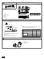
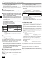
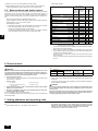
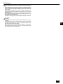
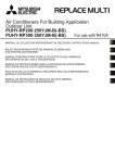
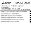
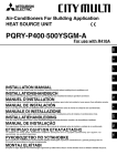
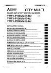
Air-Conditioners For Building Application INDOOR UNIT INSTALLATION MANUAL For safe and correct use, please read this installation manual thoroughly before installing the air-conditioner unit. GB CMB-WP108V-G 2 2.2 2.3 [Fig. 2.2.1] [Fig. 2.3.1] <A> Top view <B> Front view <A> 300 265 A 450 450 C G Service space D 89 H Indoor unit side *1 E B Inspection hole Side of outdoor unit piping Control box Side of indoor unit piping Water inlet Sub drain pan Service space Indoor unit side A Model name A B CMB-WP108V-G 1600 – 100 200 <B> G Service space B E GService space (FSub drain pan) *1 Dimensions with which pipe connection can be handled at site 120 A B C D E F G H (700) A B 250 400 2.4 [Fig. 2.4.1] CMB-WP108V-G A G A DH E H1 B Notes: *1 Indoor units that are connected to the same branch joint cannot be simultaneously operated in different operation modes. H K h2 C b C D F c d e C f (Unit: m) C Item I Difference of elevation Pipe Lengths J h1 a C A C D E F G I Outdoor unit B HBC controller Indoor unit Less than H=50 m (when the outdoor unit is higher than the indoor unit) Less than H1=40 m (when the outdoor unit is lower than the indoor unit) Twinning pipe (field supply) Less than 110 m H Less than 60 m Up to three units for 1 branch port Total capacity: less than 80 (but in same mode, cooling/heating) J Less than 15 m K Less than 15 m 3 Piping portion Allowable value Between outdoor unit and HBC controller (refrigerant pipework) A 110 or less Water pipework between indoor units and HBC controller f 60 or less Above outdoor unit H 50 or less Below outdoor unit Between indoor and outdoor units H1 40 or less Between indoor units and HBC controller h1 15 or less Between indoor units h2 15 or less 3.2 [Fig. 3.2.1] 14 30 A A B <Top view> 1 2 1 Hanging method A: Min. 30 mm A Hanging bolt ø10 (field supply) B Washer (field supply) 4 4.1 [Fig. 4.1.2] HBC CONTROLLER Outdoor unit side Unit model Model name PURY-WP200 High pressure side Low pressure side ø15.88 (Brazing) ø19.05 (Brazing) ø19.05 (Brazing) ø22.2 (Brazing) (HBC CONTROLLER) CMB-WP108V-G PURY-WP250 A B Connection to water circuit by screw connections E C D D D D D F *1 A B C D E F D Note: *1. Connection of multiple indoor units with one connection (or joint pipe) • Total capacity of connectable indoor units: Less than 80 To outdoor unit End connection (brazing) HBC controller Indoor unit Twinning pipe (field supply) Up to three units for 1 branch hole; total capacity: below 80 (but same in cooling/ heating mode) • Number of connectable indoor units: Maximum 3 Sets • Twinning pipe is field supplied. 4.2 4.3 [Fig. 4.2.1] [Fig. 4.3.1] A A Cut here B Remove brazed cap A B D A Locally procured insulating material for pipes B Bind here using band or tape. C Do not leave any opening. D Lap margin: more than 40 mm E Insulating material (field supply) F Unit side insulating material C B E F 4.4 [Fig. 4.4.1] [Fig. 4.4.2] C A 1 A: A B D F D B A B E F A D B VP-30 B VP-25 G C 2 25 cm B: 1.5 – 2 m Downward gradient of more than 1/100 Insulating material C Supporting bracket Drain discharge port E Drain hose (200 mm long, accessory) Cable tie (accessory) G Hose band (accessory) A HBC controller C Collecting pipe 3 B Indoor unit D Please ensure this length is at least 10 cm. 3 5 5.1 [Fig. 5.1.1] G F A C E G B D To A E C B Shutoff valve D Pressure reducing valve F Refrigerant pipes Expansion tank Strainer Water inlet Drain pipe HBC controller sample installation 5.2 [Fig. 5.2.1] A D A Locally procured insulating material for pipes B Bind here using band or tape. C Do not leave any opening. D Lap margin: more than 40 mm E Insulating material (field supply) F Unit side insulating material C B E F [Fig. 5.2.2] Connection size Indoor unit Water outlet Water out Water return Rc 3/4 screw Rc 3/4 screw I.D. 20 mm I.D. 20 mm PEFY-WP·VMA A B D D D *1 A B C D E F Note: *1. Connection of multiple indoor units with one connection (or joint pipe) • Total capacity of connectable indoor units: Less than 80 Water pipework is screw connections E C D Pipe size Water inlet D D • Number of connectable indoor units: Maximum 3 Sets • Selection of water piping Select the size according to the total capacity of indoor units to be installed downstream. Please group units that operate on 1 branch. • F To outdoor unit End connection (brazing) HBC controller Indoor unit Twinning pipe (field supply) Up to three units for 1 branch hole; total capacity: below 80 (but in same mode, cooling/heating) [Fig. 5.2.3] A B 6 [Fig. 6.0.1] C D E A B C D E HBC controller Water pipe Pressure reducing valve Strainer Shut off valve D C B A E 4 A B C D E Control box Power source wiring ø21 hole (closed rubber bushing) Transmission wiring Clip cables here Contents 1. 2. 3. Safety precautions .............................................................................................5 1.1. Before installation and electric work .................................................5 1.2. Precautions for devices that use R410A refrigerant .........................6 1.3. Before installation .............................................................................6 1.4. Before installation (relocation) - electrical work ................................6 1.5. Before starting the test run ...............................................................6 Selecting an installation site...............................................................................7 2.1. About the product .............................................................................7 2.2. Installation site..................................................................................7 2.3. Securing installation and service space ...........................................7 2.4. Checking the installation site ............................................................7 Installing the HBC controller ..............................................................................7 3.1. Checking the accessories with the HBC controller...........................7 4. 5. 6. 7. 8. 3.2. Installing HBC controllers .................................................................7 Connecting refrigerant pipes and drain pipes ....................................................8 4.1. Connecting refrigerant pipes ............................................................8 4.2. Refrigerant piping work ....................................................................8 4.3. Insulating refrigerant pipes ...............................................................8 4.4. Drain piping work..............................................................................8 Connecting water pipework................................................................................9 5.1. Important notes on water pipework installation ................................9 5.2. Water pipe insulation........................................................................9 5.3. Water treatment and quality control ...............................................10 Electrical work..................................................................................................10 Setting addresses and operating units.............................................................10 Test run............................................................................................................11 1.1. Before installation and electric work Before installing the unit, make sure you read all the “Safety precautions”. The “Safety precautions” provide very important points regarding safety. Make sure you follow them. Symbols used in the text • • • Warning: Describes precautions that should be observed to prevent danger of injury or death to the user. Caution: Describes precautions that should be observed to prevent damage to the unit. • • • Symbols used in the illustrations : Indicates an action that must be avoided. • : Indicates that important instructions must be followed. • : Indicates a part which must be grounded. : Beware of electric shock. (This symbol is displayed on the main unit label.) <Color: Yellow> • • Warning: Carefully read the labels affixed to the main unit. • HIGH VOLTAGE WARNING: • • • Control box houses high-voltage parts. When opening or closing the front panel of the control box, do not let it come into contact with any of the internal components. Before inspecting the inside of the control box, turn off the power, keep the unit off for at least 10 minutes. • • Warning: • • • • • • • • • Ask the dealer or an authorized technician to install the air conditioner. - Improper installation by the user may result in water leakage, electric shock, or fire. Install the unit at a place that can withstand its weight. - Failure to do so may cause the unit to fall down, resulting in injuries and damage to the unit. Use the specified cables for wiring. Make the connections securely so that the outside force of the cable is not applied to the terminals. - Inadequate connection and fastening may generate heat and cause a fire. Prepare for earthquakes and install the unit at the specified place. - Improper installation may cause the unit to fall down and result in injury and damage to the unit. Always use accessories specified by Mitsubishi Electric. - Ask an authorized technician to install the accessories. Improper installation by the user may result in water leakage, electric shock, or fire. Never repair the unit. If the air conditioner must be repaired, consult the dealer. - If the unit is repaired improperly, water leakage, electric shock, or fire may result. If the supply cord is damaged, it must be replaced by the manufacturer, its service agent or similarly qualified persons in order to avoid a hazard. If refrigerant gas leaks during installation work, ventilate the room. - If the refrigerant gas comes into contact with a flame, poisonous gases will be released. Install the air conditioner according to this Installation Manual. - If the unit is installed improperly, water leakage, electric shock, or fire may result. • • • • • Do not modify or adjust safety protection devices. - Shorting of pressure or temperature switches to force operation may lead to damage, fire, explosions etc... - Do not change the set values as this may lead to damage, fire, explosions etc... - Use of any product except that specified by this company may lead to damage, fire, explosions etc... Do not spray water on electrical parts. - This could lead to shorting, fire, smoke, electrical shock, unit failure etc... Do not create a situation where the refrigeration circuit is sealed yet incomplete with oil or refrigerant in the system. - This may result in an explosion. Do not touch electrical components during or directly after operation. - This may lead to burns. Put covers on control and terminal boxes. - Shock due to ingress of dust, water, smoke, fire etc. may result. Do not operate with guards or panels removed. - Injury due to rotating parts, electric shock due to high voltage or burns due to high temperatures may result. Do no sit, ride or place objects on the unit. - Injury due to the unit falling may result. Use the appropriate safety gear. - High voltages may result in electric shock. - Hot parts may result in burns. Recover the refrigerant in the unit. - Reuse the refrigerant or have it disposed of by a specialist. - Release of refrigerant may damage the environment. Clear the pipework of remnant gas and oil. - Failure to do so could lead to an eruption of flames and burns if the pipework is heated. Vacuum dry the refrigerant pipework. Do not replace with a refrigerant that has not been specified. - This could lead to explosions, fire. Do not touch the onsite pipework ends. - This could damage the pipework leading to refrigerant leaks and oxygen deficiency. Have all electric work done by a licensed electrician according to “Electric Facility Engineering Standard” and “Interior Wire Regulations” and the instructions given in this manual and always use a dedicated power supply. - If the power source capacity is inadequate or electric work is performed improperly, electric shock and fire may result. Securely install the cover of control box. - If the cover is not installed properly, dust or water may enter the outdoor unit and fire or electric shock may result. When installing and moving the air conditioner to another site, do not charge it with a refrigerant different from the refrigerant specified on the unit. - If a different refrigerant or air is mixed with the original refrigerant, the refrigerant cycle may malfunction and the unit may be damaged. If the air conditioner is installed in a small room, measures must be taken to prevent the refrigerant concentration from exceeding the safety limit if the refrigerant should leak. - Consult the dealer regarding the appropriate measures to prevent the safety limit from being exceeded. Should the refrigerant leak and cause the safety limit to be exceeded, hazards due to lack of oxygen in the room could result. When moving and reinstalling the air conditioner, consult the dealer or an authorized technician. - If the air conditioner is installed improperly, water leakage, electric shock, or fire may result. After completing installation work, make sure that refrigerant gas is not leaking. - If the refrigerant gas leaks and is exposed to a fan heater, stove, oven, or other heat source, it may generate noxious gases. 5 GB 1. Safety precautions • • • • • • Do not reconstruct or change the settings of the protection devices. - If the pressure switch, thermal switch, or other protection device is shorted or operated forcibly, or parts other than those specified by Mitsubishi Electric are used, fire or explosion may result. To dispose of this product, consult your dealer. The installer and system specialist shall secure safety against leakage according to local regulation or standards. - Choose the appropriate wire size and the switch capacities for the main power supply described in this manual if local regulations are not available. Pay special attention to the place of installation, such as basement, etc. where refrigeration gas can accumulate, since refrigerant is heavier than the air. This appliance is not intended for use by persons (including children) with reduced physical, sensory or mental capabilities, or lack of experience and knowledge, unless they have been given supervision or instruction concerning use of the appliance by a person responsible for their safety. Children should be supervised to ensure that they do not play with the appliance. 1.3. Before installation Caution: • • • • GB • 1.2. Precautions for devices that use R410A refrigerant Caution: • • • • • • • • • • • Do not use existing refrigerant piping. - The old refrigerant and refrigerant oil in the existing piping contains a large amount of chlorine which may cause the refrigerant oil of the new unit to deteriorate. - R410A is a high-pressure refrigerant and can cause the existing piping to burst. Use refrigerant piping made of phosphorus deoxidized copper and copper alloy seamless pipes and tubes. In addition, be sure that the inner and outer surfaces of the pipes are clean and free of hazardous sulphur, oxides, dust/dirt, shaving particles, oils, moisture, or any other contaminant. - Contaminants on the inside of the refrigerant piping may cause the refrigerant residual oil to deteriorate. Store the piping to be used during installation indoors and keep both ends of the piping sealed until just before brazing. (Store elbows and other joints in a plastic bag.) - If dust, dirt, or water enters the refrigerant cycle, deterioration of the oil and compressor failure may result. Apply a small amount of ester oil, ether oil, or alkyl benzene to flares. (for indoor unit) - Infiltration of a large amount of mineral oil may cause the refrigerant oil to deteriorate. Use liquid refrigerant to fill the system. - If gas refrigerant is used to fill the system, the composition of the refrigerant in the cylinder will change and performance may drop. Do not use a refrigerant other than R410A. - If another refrigerant (R22, etc.) is mixed with R410A, the chlorine in the refrigerant may cause the refrigerant oil to deteriorate. Use a vacuum pump with a reverse flow check valve. - The vacuum pump oil may flow back into the refrigerant cycle and cause the refrigerant oil to deteriorate. Do not use the following tools that are used with conventional refrigerants. (Gauge manifold, charge hose, gas leak detector, reverse flow check valve, refrigerant charge base, refrigerant recovery equipment) - If the conventional refrigerant and refrigerant oil are mixed in the R410A, the refrigerant may deteriorate. - If water is mixed in the R410A, the refrigerant oil may deteriorate. - Since R410A does not contain any chlorine, gas leak detectors for conventional refrigerants will not react to it. Do not use a charging cylinder. - Using a charging cylinder may cause the refrigerant to deteriorate. Do not use antioxidant or leak-detection additive. Be especially careful when managing the tools. - If dust, dirt, or water gets into the refrigerant cycle, the refrigerant may deteriorate. 1.4. Before installation (relocation) - electrical work Caution: • • • • • • • • • • Ground the unit. - Do not connect the ground wire to gas or water pipes, lightning rods, or telephone ground lines. Improper grounding may result in electric shock. Install the power cable so that tension is not applied to the cable. - Tension may cause the cable to break and generate heat and cause a fire. Install a leak circuit breaker, as required. - If a leak circuit breaker is not installed, electric shock may result. Use power line cables of sufficient current carrying capacity and rating. - Cables that are too small may leak, generate heat, and cause a fire. Use only a circuit breaker and fuse of the specified capacity. - A fuse or circuit breaker of a larger capacity, or the use of substitute simple steel or copper wire may result in a general unit failure or fire. Do not wash the air conditioner units. - Washing them may cause an electric shock. Be careful that the installation base is not damaged by long use. - If the damage is left uncorrected, the unit may fall and cause personal injury or property damage. Install the drain piping according to this Installation Manual to ensure proper drainage. Wrap thermal insulation around the pipes to prevent condensation. - Improper drain piping may cause water leakage causing damage to furniture and other possessions. Be very careful about transporting the product. - One person should not carry the product. Its weight is in excess of 20 kg. - Some products use PP bands for packaging. Do not use any PP bands as a means of transportation. It is dangerous. Safely dispose of the packing materials. - Packing materials, such as nails and other metal or wooden parts, may cause stabs or other injuries. - Tear apart and throw away plastic packaging bags so that children will not play with them. If children play with a plastic bag which has not been torn apart, they face the risk of suffocation. 1.5. Before starting the test run Caution: • • • • • 6 Do not install the unit where combustible gas may leak. - If the gas leaks and accumulates around the unit, an explosion may result. Do not use the air conditioner where food, pets, plants, precision instruments, or artwork are kept. - The quality of the food, etc. may deteriorate. Do not use the air conditioner in special environments. - Oil, steam, sulfuric smoke, etc. can significantly reduce the performance of the air conditioner or damage its parts. When installing the unit in a hospital, communication station, or similar place, provide sufficient protection against noise. - Inverter equipment, private power generator, high-frequency medical equipment, or radio communication equipment may cause the air conditioner to operate erroneously, or fail to operate. On the other hand, the air conditioner may affect such equipment by creating noise that disturbs medical treatment or image broadcasting. Do not install the unit on or over things that are subject to water damage. - When the room humidity exceeds 80 % or when the drain pipe is clogged, condensation may drip from the indoor unit or BC controller. Perform collective drainage work together with the outdoor unit, as required. Turn on the power at least 12 hours before starting operation. - Starting operation immediately after turning on the main power switch can result in irreversible damage to internal parts. Keep the power switch turned on during the operational season. Do not touch the switches with wet fingers. - Touching a switch with wet fingers can result in an electric shock. Do not touch the refrigerant pipes during and immediately after operation. - During and immediately after operation, the refrigerant pipes may be hot or cold, depending on the condition of the refrigerant flowing through the refrigerant piping, compressor, and other refrigerant cycle parts. Your hands may suffer burns or frostbite if you touch the refrigerant pipes. Do not operate the air conditioner with the panels and guards removed. - Rotating, hot, or high-voltage parts can cause injuries. Do not turn off the power immediately after stopping operation. - Always wait at least 5 minutes before turning off the power. Otherwise, drainage water leakage or mechanical failure of sensitive parts may occur. 2. Selecting an installation site 2.1. About the product Caution: This unit uses R410A-type refrigerant. • Piping for systems using R410A may be different from that for systems using conventional refrigerant because the design pressure in systems using R410A is higher. Refer to the Data Book for more information. • Some of the tools and equipment used for installation with systems that use other types of refrigerant cannot be used with the systems using R410A. Refer to the Data Book for more information. • Do not use the existing piping, as it contains chlorine, which is found in conventional refrigerating machine oil and refrigerant. This chlorine will deteriorate the refrigerant machine oil in the new equipment. The existing piping must not be used as the design pressure in systems using R410A is higher than that in the systems using other types of refrigerant and the existing pipes may burst. • Be sure to install the unit horizontally. Install the HBC level (less than 1° tilt), so that the drain pan can function correctly. Install the HBC in an environment where the temperature in always above 0°C. • 2.3. Securing installation and service space 1. For hanging from the ceiling (This is a reference view showing the least installation space.) [Fig. 2.3.1] (P.2) <A> Top view <B> Front view A Inspection hole B Side of outdoor unit piping C Control box D Side of indoor unit piping E Water inlet F Sub drain pan G Service space H Indoor unit side *1 Dimensions with which pipe connection can be handled at site 2.2. Installation site • Install the unit in a place not exposed to rain. The HBC controller is designed to be installed indoors. • Install the unit with adequate space around it for servicing. • Do not install the unit in a place that would result in the piping length restrictions being exceeded. • Install the unit in a place not exposed to direct radiant heat from other heat sources. • Do not install the unit in any oily steamy place or near any machine that generates high frequencies. Doing so may cause a risk of fire, erroneous operation or condensation. • Install the unit in a location where the noise from the unit will not be a problem. (Install indoor unit and HBC controller at least 5 m away from each other when installed in a space with low background noise, e.g., hotel rooms). • Allow enough space and access to ensure water piping, refrigerant piping and electrical wiring can be easily connected. • Avoid places exposed to the generation, inflow, accumulation or leakage of flammable and sulfuric gases. • Ensure a downward gradient of at least 1/100 for drain piping. • Properly install the unit on a stable, load-bearing surface. A B 1600 – 2.4. Checking the installation site Check that the difference of elevation between indoor and outdoor units and the length of refrigerant piping are within the following limitations. 1. CMB-WP108V-G [Fig. 2.4.1] (P.2) A C D E F G I Outdoor unit B HBC controller Indoor unit Less than H=50 m (when the outdoor unit is higher than the indoor unit) Less than H1=40 m (when the outdoor unit is lower than the indoor unit) Twinning pipe (field supply) Less than 110 m H Less than 60 m Up to three units for 1 branch port Total capacity: less than 80 (but in same mode, cooling/heating) J Less than 15 m K Less than 15 m (Unit: m) 1. For hanging from the ceiling [Fig. 2.2.1] (P.2) • Provide 2 inspection holes 450 mm square in the ceiling surface as shown in [Fig. 2.3.1] (P.2). Item Difference of elevation Pipe Lengths • Model name CMB-WP108V-G GB • Install the unit in a suitable location (such as in the ceiling of a corridor or in the bathroom etc) away from places regularly occupied. Avoid installing in the center of a room. • Ensure hanging bolts are of sufficient pull out strength. • Install a sub drain pan (sold separately, PAC-HBC01DP-E). If leakage from underneath the HBC would cause no problem in the installed location, installation of the sub drain pan is not necessary. [Fig. 2.2.1] (P.2) [Fig. 2.3.1] (P.2) Warning: Be sure to install the unit in a place that can sustain the entire weight. If there is a lack of strength, it may cause the unit to fall down, resulting in an injury. Piping portion Allowable value Between outdoor unit and HBC controller (refrigerant pipework) A 110 or less Water pipework between indoor units and HBC controller f 60 or less Above outdoor unit H 50 or less Below outdoor unit H1 40 or less Between indoor units and HBC controller h1 15 or less Between indoor units h2 15 or less Between indoor and outdoor units Notes: *1 Indoor units that are connected to the same branch joint cannot be simultaneously operated in different operation modes. 3. Installing the HBC controller 3.1. Checking the accessories with the HBC controller The following items are supplied with each HBC controller. Model name CMB-WP108V-G Item 3.2. Installing HBC controllers Installing hanging bolts Install locally procured hanging bolts (threaded rod) following the procedure given in the figure. The hanging bolt size is ø10 (M10 screw). To hang the unit, use a lifting machine to lift and pass it through the hanging bolts. The suspension bracket has an oval hole. Use a large diameter washer. [Fig. 3.2.1] (P.2) Qty 1 Drain hose 1 2 Cable tie 1 3 Hose band 1 4 Refrigerant connection pipe 2 1 Hanging method A: Min.30 mm A Hanging bolt ø10 (field supply) B Washer (field supply) Be sure to install the HBC controller horizontally. Check using a level. If the controller is installed at an angle, drain water may leak out. If the unit is slanted, loosen the fixing nuts on the hanging brackets to adjust its position. Install the HBC level (less than 1° tilt), so that the drain pan can function correctly. • Be sure to install the unit horizontally. Install the HBC level (less than 1° tilt), so that the drain pan can function correctly. Caution: 7 4. Connecting refrigerant pipes and drain pipes 4.1. Connecting refrigerant pipes 4.3. Insulating refrigerant pipes 1. Be sure to use non-oxidative brazing where necessary. If you do not use non-oxidative brazing, it may clog the pipes. When brazing the outdoor unit connecting port of HBC controller, supply nitrogen gas into the pipe between the outdoor unit and HBC controller. Be sure to add insulation work to refrigerant piping by covering high-pressure pipe and low-pressure pipe separately with enough thickness heat-resistant polyethylene foam, so that no gap is observed in the joint between the HBC controller and insulating material, and insulating materials themselves. When insulation work is insufficient, there is a possibility of condensation. Pay special attention to insulation work in the ceiling plenum. 2. After completing pipe connection, support the pipes to ensure that load is not imparted to the HBC controller’s end connections. [Fig. 4.3.1] (P.3) Warning: When installing and moving the unit, do not charge it with refrigerant other than the refrigerant (R410A) specified on the unit. - Mixing of a different refrigerant, air, etc. may cause the refrigerant cycle to malfunction and result in severe damage. A B D F • Caution: Use refrigerant piping made of phosphorus deoxidized copper and copper alloy seamless pipes and tubes. In addition, be sure that the inner and outer surfaces of the pipes are clean and free of hazardous sulphur, oxides, dust/ dirt, swarf, oils, moisture, or any other contaminants. - R410A is a high-pressure refrigerant and can cause the existing piping to burst. Store the piping to be used during installation indoors and keep both ends of the piping sealed until just before brazing. (Store elbows and other joints in a plastic bag.) - If dust, dirt, or water enters the refrigerant cycle, deterioration of the oil and compressor failure may result. - Infiltration of a large amount of mineral oil may cause the refrigerant oil to deteriorate. Do not vent R410A into the atmosphere. R410A is a Fluorinated Greenhouse gas, covered by the Kyoto Protocol with a Global Warming Potential (GWP) = 1975. • • • 1. Size of HBC controller’s end connection piping [Fig. 4.1.2] (P.3) HBC CONTROLLER Unit model Outdoor unit side GB • Model name High pressure side Low pressure side ø15.88 (Brazing) ø19.05 (Brazing) ø19.05 (Brazing) ø22.2 (Brazing) PURY-WP200 (HBC CONTROLLER) CMB-WP108V-G PURY-WP250 A B C D E F To outdoor unit End connection (brazing) HBC controller Indoor unit Twinning pipe (field supply) Up to three units for 1 branch hole; total capacity: below 80 (but in same mode, cooling/heating) Note: Be sure to use non-oxidative brazing. Locally procured insulating material for pipes Bind here using band or tape. C Do not leave any opening. Lap margin: more than 40 mm E Insulating material (field supply) Unit side insulating material Insulation materials for the pipes to be added on site must meet the following specifications: Outdoor unit High-pressure pipe 10 mm or more -HBC controller Low-pressure pipe 20 mm or more Temperature Resistance 100°C min. • Installation of pipes in a high-temperature high-humidity environment, such as the top floor of a building, may require the use of insulation materials thicker than the ones specified in the chart above. • When certain specifications presented by the client must be met, ensure that they also meet the specifications on the chart above. • The brazed connections must be covered with insulation, with its seam facing upward and fastened with the bands. 4.4. Drain piping work 1. Drain piping work • Ensure that the drain piping is downward (sloped gradient of more than 1/100) to the outdoor (discharge) side. If it is impossible to take any downward pitch, use an optionally available drain-up mechanism to obtain a downward pitch of more than 1/100. • Ensure that any cross-wise drain piping is less than 20 m. If the drain piping is long, support it with metal brackets to prevent it from bending, warping, or vibrating. • Connect the supplied drain hose to the discharge port on the unit body. Use hard vinyl chloride pipes VP-25 (ø32) for drain piping (2). Tighten the supplied drain hose onto the discharge port using the supplied hose band. (For this, do not use any adhesive because the drain hose will need to be removed for servicing at a later date.) • Do not use any odor trap around the discharge port. [Fig. 4.4.1] (P.3) A: A B D F • 25 cm Downward gradient of more than 1/100 Insulating material Drain discharge port Cable tie (accessory) B: 1.5 – 2 m C Supporting bracket E Drain hose (200 mm long, accessory) G Hose band (accessory) As shown in 3, install a collecting pipe about 10 cm below the drain ports and give it a downward pitch of more than 1/100. This collecting pipe should be of VP-30. • Set the end of drain piping in a place without any risk of odor generation. • Do not put the end of drain piping into any drain where ionic gases are generated. After connecting the refrigerant pipes of the outdoor units with the outdoor units’ stop valves remained fully closed, evacuate vacuum from the outdoor units’ stop valve service ports. After completing the above, open the outdoor units’ stop valves. This connects the refrigerant circuit (between outdoor and HBC controller) completely. How to handle stop valves is described on each outdoor unit. • Drain piping may be installed in any direction. However, please be sure to observe the above instructions. Notes: • After pipe connection, be sure to check that there is no gas leakage, using a leak detector or soap-and-water solution. • Before brazing the refrigerant piping, always wrap the piping on the main body, and the thermal insulation piping, with damp cloths to prevent heat shrinkage and burning the thermal insulation tubing. Take care to ensure that the flame does not come into contact with the main body itself. • Do not use leak-detection additives. 2. Discharge test After completing drain piping work, open the HBC controller panel, and test drain discharge using a small amount of water. Also, check to see that there is no water leakage from the connections. 4.2. Refrigerant piping work Warning: Do not mix anything other than the specified refrigerant (R410A) into the refrigerating cycle when installing or moving. Mixing air may cause the refrigerating cycle to reach abnormally high temperature, resulting in burst pipes. Caution: Cut the tip of the outdoor unit piping, remove the gas, and then remove the brazed cap. [Fig. 4.2.1] (P.3) A Cut here 8 B Remove brazed cap [Fig. 4.4.2] (P.3) A HBC controller C Collecting pipe B Indoor unit D Please ensure this length is at least 10 cm. 3. Insulating drain pipes Provide sufficient insulation to the drain pipes just as for refrigerant pipes. Caution: Be sure to provide drain piping with heat insulation in order to prevent excess condensation. Without drain piping, water may leak from the unit causing damage to your property. 5. Connecting water pipework Please observe the following precautions during installation. • 5.1. Important notes on water pipework installation Installation of pipes in a high-temperature high-humidity environment, such as the top floor of a building, may require the use of insulation materials thicker than the ones specified in the chart above. • When certain specifications presented by the client must be met, ensure that they also meet the specifications on the chart above. • • • • • • • • • • • • • • • • The design pressure of the HBC water system is 0.6MPa. Use water pipe-work with a design pressure of at least 1.0MPa. When performing a water leak check, please do not allow the water pressure to go above 0.3MPa. Please connect the water pipework of each indoor unit to the connect port on the HBC. Failure to do so will result in incorrect running. Please list the indoor units on the naming plate in the HBC unit with addresses and end connection numbers. If the number of indoor units are less than the number of ports on the HBC, the unused ports can be capped. Without a cap, water will leak. Use the reverse-return method to insure proper pipe resistance to each unit. Provide some joints and bulbs around inlet/outlet of each unit for easy maintenance, checkup, and replacement. Install a suitable air vent on the water pipe. After flowing water through the pipe, vent any excess air. Secure the pipes with metal fitting, positioning them in locations to protect pipes against breakage and bending. Do not confuse the water intake and outlet piping. (Error code 5102 will appear on the remote controller if a test run is performed with the pipe-work installed incorrectly (inlet connected to outlet and vice versa).) This unit doesn’t include a heater to prevent freezing within tubes. If the water flow is stopped on low ambient, drain the water out. The unused knockout holes should be closed and the refrigerant pipes, water pipes, power source and transmission wires access holes should be filled with putty. Install water pipe so that the water flow rate will be maintained. Wrap sealing tape as follows. 1 Wrap the joint with sealing tape following the direction of the threads (clockwise), do not wrap the tape over the edge. 2 Overlap the sealing tape by two-thirds to three-fourths of its width on each turn. Press the tape with your fingers so that it is tight against each thread. 3 Do not wrap the 1.5th through 2nd farthest threads away from the pipe end. 4. Expansion tank • Install an expansion tank to accommodate expanded water. Expansion tank selection criteria: • The water containment volume of the HBC and the indoor unit. (Unit: L) Unit model Water volume HBC Controller 10 PEFY-WP20VMA 0.7 PEFY-WP25VMA 1 PEFY-WP32VMA PEFY-WP40VMA 1.8 PEFY-WP50VMA • The maximum water temperature is 60°C. • The minimum water temperature is 5°C. • The circuit protection valve set pressure is 370-490kPa. • The circulation pump head pressure is 0.24MPa. 5. Leakproof the water pipework, valves and drain pipework. Leakproof all the way to, and include pipe ends so that condensation cannot enter the insulated pipework. 6. Apply caulking around the ends of the insulation to prevent condensation getting between the pipework and insulation. 7. Add a drain valve so that the unit and pipework can be drained. 8. Ensure there are no gaps in the pipework insulation. Insulate the pipework right up to the unit. 9. Ensure that the gradient of the drain pan pipework is such that discharge can only flow out. 10. HBC water pipe connection sizes and pipe sizes. [Fig. 5.2.2] (P.4) Connection size Indoor unit Hold the pipe on the unit side in place with a spanner when installing the pipes or strainer. Tighten screws to a torque of 40 N·m. If there is a risk of freezing, carry out a procedure to prevent it. When connecting heat source unit water piping and on site water piping, apply liquid sealing material for water piping over the sealing tape before connection. Please use copper or plastic pipes for the water circuit. Do not use steel or stainless steel pipework. Furthermore, when using copper pipe-work, use a non-oxidative brazing method. Oxidation of the pipe-work will reduce the pump life. PEFY-WP·VMA Pipe size Water inlet Water outlet Water out Water return Rc 3/4 screw Rc 3/4 screw I.D. 20 mm I.D. 20 mm A B C Water pipework is screw connections E Example of heat source unit installation (using left piping) [Fig. 5.1.1] (P.4) A C E G D B Shutoff valve D Pressure reducing valve F Refrigerant pipes Expansion tank Strainer Water inlet Drain pipe 2. List indoor unit model names in the name plate on the HBC controller control box (for identification purposes), and HBC controller end connection numbers and address numbers in the name plate on the indoor unit side. Seal unused end connections using cover caps (field supply, dezincification resistant brass (DZR) or bronze only). Not replacing the rubber end caps will lead to water leakage. 3. Be sure to add insulation work to water piping by covering water pipework separately with enough thickness heat-resistant polyethylene, so that no gap is observed in the joint between indoor unit and insulating material, and insulating materials themselves. When insulation work is insufficient, there is a possibility of condensation, etc. Pay special attention to insulation work in the ceiling plenum. [Fig. 5.2.1] (P.4) A B D F • Locally procured insulating material for pipes Bind here using band or tape. C Do not leave any opening. Lap margin: more than 40 mm E Insulating material (field supply) Unit side insulating material Insulation materials for the pipes to be added on site must meet the following specifications: HBC controller -indoor unit • 20 mm or more This specification is based on copper for water piping. When using plastic pipework, choose a thickness based on the plastic pipe performance. D D *1 A B C D E F 5.2. Water pipe insulation 1. Connect the water pipes of each indoor unit to the same (correct) end connection numbers as indicated on the indoor unit connection section of each HBC controller. If connected to wrong end connection numbers, there will be no normal operation. D D D F To outdoor unit End connection (brazing) HBC controller Indoor unit Twinning pipe (field supply) Up to three units for 1 branch hole; total capacity: below 80 (but in same mode, cooling/heating) Note: *1. Connection of multiple indoor units with one connection (or joint pipe) • Total capacity of connectable indoor units: Less than 80 • Number of connectable indoor units: Maximum 3 Sets • Selection of water piping • Select the size according to the total capacity of indoor units to be installed downstream. Please group units that operate on 1 branch. 11. Please refer to the [Fig. 5.2.3] when connecting the water supply. [Fig. 5.2.3] (P.4) A HBC controller C Pressure reducing valve E Shut off valve B Water pipe D Strainer 12. Use formula 0.1 < 0.01 + 0.01 x A < 0.16 for the supply pressure range to be used. (A: Head pressure (m) between the HBC and the highest indoor unit) If the supply pressure is greater than 0.16 MPa, use a pressure reducing valve to keep the pressure within the range. If the head pressure is unknown, set it to 0.16 MPa. 13. Install a shut off valve and strainer in a place that is easy to operate and makes maintenance work easy. 14. Apply insulation to the indoor unit pipework, strainer, shut off valve, and pressure reducing valve. 9 GB • • • 15. Please do not use a corrosion inhibitor in the water system. 2 Water quality standard 16. When installing the HBC unit in an environment which may drop below 0°C, please add antifreeze (Propylene Glycol only) to the circulating water. Low to mid-range temperature water system Items 5.3. Water treatment and quality control To preserve water quality, use the closed type of water circuit. When the circulating water quality is poor, the water heat exchanger can develop scale, leading to a reduction in heat-exchange power and possible corrosion. Pay careful attention to water processing and water quality control when installing the water circulation system. • Removing of foreign objects or impurities within the pipes. pH (25°C) [77°F] Standard items Electric conductivity During installation, make sure that foreign objects, such as welding fragments, sealant particles, or rust, do not enter the pipes. • Water Quality Processing 1 Depending on the quality of the cold-temperature water used in the airconditioner, the copper piping of the heat exchanger may corrode. Regular water quality processing is recommended. If a water supply tank is installed, keep air contact to a minimum, and keep the level of dissolved oxygen in the water no higher than 1mg/ℓ. Reference items Make-up water 7.0 ~ 8.0 7.0 ~ 8.0 Scaleforming (mS/m) (25°C) [77°F] (mg Cl-/ℓ) 50 or less 50 or less (mg SO42-/ℓ) 50 or less 50 or less 50 or less 50 or less Total hardness (mg CaCO3/ℓ) 70 or less 70 or less Calcium hardness (mg CaCO3/ℓ) 50 or less 50 or less (mg SiO2/ℓ) 30 or less 30 or less Chloride ion Acid consumption (pH4.8) (mg CaCO3/ℓ) Iron (mg Fe/ℓ) 1.0 or less 0.3 or less Copper (mg Cu/ℓ) 1.0 or less 0.1 or less Sulfide ion (mg S2-/ℓ) Ammonium ion Corrosive 30 or less 30 or less (µ s/cm) (25°C) [77°F] [300 or less] [300 or less] Sulfate ion Ionic silica GB Recirculating water [20<T<60°C] [68<T<140°F] Tendency not to be detected not to be detected (mg NH4+/ℓ) 0.3 or less 0.1 or less Residual chlorine (mg Cl/ℓ) 0.25 or less 0.3 or less Free carbon dioxide (mg CO2/ℓ) 0.4 or less 4.0 or less Ryzner stability index 6.0 ~ 7.0 – Reference : Guideline of Water Quality for Refrigeration and Air Conditioning Equipment. (JRA GL02E-1994) 3 Consult with a specialist about water quality control methods and calculations before using anti-corrosive solutions. 4 When replacing a previously installed air conditioning device (even when only the heat exchanger is being replaced), first conduct a water quality analysis and check for possible corrosion. Corrosion can occur in cold-water systems even if there has been no prior signs of corrosion. If the water quality level has dropped, adjust water quality before replacing the unit. 6. Electrical work Consult all related regulations and power companies beforehand. The switch capacity of the main power to BC controllers and the wire size are as follows: Warning: Switch (A) Electrical work should be handled by qualified electrical engineers in accordance with all related regulations and attached instruction manuals. Special circuits should also be used. If there is a lack of power capacity or a deficiency in electrical work, it may cause a risk of electric shock or fire. • Connect all wires securely. Fix power source wiring to control box by using buffer bushing for tensile force (PG connection or the like). [Fig. 6.0.1] (P.4) A Control box C ø21 hole (closed rubber bushing) E Clip cables here Never connect the power cable to the terminal board for control cables. (Otherwise it may be broken.) Be sure to wire between the control wire terminal boards for indoor unit, outdoor unit and HBC controller. Use non-polarized 2-wire as transmission cables. Use 2-core shielding cables (CVVS, CPEVS) of more than 1.25 mm2 in diameter as transmission cables. Fuse Molded case circuit breaker Earth leakage breaker Wire size 16 16 20 A 20 A 30 mA 0.1 s or less 1.5 mm2 • For other detailed information, refer to the outdoor unit installation manual. • Power supply cords of appliances shall not be lighter than design 245 IEC 53 or 227 IEC 53. • A switch with at least 3 mm contact separation in each pole shall be provided by the Air conditioner installation. B Power source wiring D Transmission wiring Capacity Caution: Do not use anything other than the correct capacity fuse and breaker. Using fuse, conductor or copper wire with too large capacity may cause a risk of malfunction or fire. Ensure that the outdoor units are put to the ground. Do not connect the earth cable to any gas pipe, water pipe, lightening rod or telephone earth cable. Incomplete grounding may cause a risk of electric shock. 7. Setting addresses and operating units The address switch of each HBC controller is set to “000” when shipped from the factory. • Set the address switch to 1 + the address of the outdoor unit. • 10 The HBC controller address should generally be set to 1 + the address of the outdoor unit. However, if this would result in it having the same address as another outdoor unit, set the address between 51 and 100, making sure that it is different from the address of other controllers. Please refer to the outdoor unit installation manual. 8. Test run Before commencing a test run please check the following: • After installing, piping and wiring the indoor units and HBC controllers, check to see again that there is no refrigerant leakage, water leakage, the indoor unit inlet and outlet piped backwards, and no slack on power and control cables. (Error code 5102 will appear on the remote controller if a test run is performed with the pipe-work installed incorrectly (inlet connected to outlet and vice versa).) Use a 500 V tester to check that there is an insulation resistance of more than 1.0 MΩ between the power terminal block and the ground. If it is less than 1.0 MΩ, do not operate the unit. When water has been supplied to the water pipework, purge the system of air. The details of air purging can be found separately in the water circuit maintenance manual. Caution: • • Never measure the insulation resistance of the terminal block for any control cables. Incomplete purging of the air in the system, closing of the valves upstream or down stream of the pump etc. may cause the pump to operate with no water flow and thus lead to pump failure. Ensure that the power is off when replacing a pump. Do not remove or attach the pump connector with the power on. After turning off the power, wait 10 minutes before commencing work. GB • 11 This product is designed and intended for use in the residential, commercial and light-industrial environment. The product at hand is based on the following EU regulations: • Low Voltage Directive 2006/95/EC • Electromagnetic Compatibility Directive 2004/108/EC Please be sure to put the contact address/telephone number on this manual before handing it to the customer. HEAD OFFICE: TOKYO BLDG., 2-7-3, MARUNOUCHI, CHIYODA-KU, TOKYO 100-8310, JAPAN Authorized representative in EU:MITSUBISHI ELECTRIC EUROPE B.V. HARMAN HOUSE, 1 GEORGE STAREET, UXBRIDGE, MIDDLESEX UB8 1QQ, U.K. WT06421X02 Printed in Japan