1
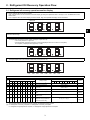
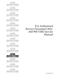
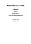
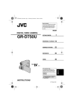
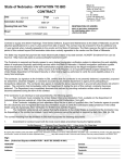
Air Conditioners For Building Application Outdoor Unit MANUEL D’INSTRUCTIONS POUR LA COLLECTE D’HUILE MINÉRALE (RÉCUPÉRATION DE L’HUILE FRIGORIFIQUE) RACCOLTA DELL’OLIO MINERALE (RECUPERO DELL’OLIO REFRIGERANTE) MANUALE DI ISTRUZIONI I MANUAL DE INSTRUÇÕES DE RECOLHA DE ÓLEO MINERAL (RECUPERAÇÃO DO ÓLEO REFRIGERANTE) P MANUAL DE INSTRUCCIONES PARA LA RECOGIDA DE ACEITE MINERAL (RECUPERACIÓN DE ACEITE REFRIGERANTE) D ANLEITUNGSHANDBUCH FÜR DIE MINERALÖLSAMMLUNG (KÄLTEMITTELÖLENTNAHME) F MINERAL OIL COLLECTION (REFRIGERANT OIL RECOVERY) INSTRUCTIONS MANUAL GB For use with R410A E PURY-RP200·250·300YJM-B(-BS) 1. Unit Components Figure 1 Top view of the refrigerant pipes inside an outdoor unit H GB I CJ4 CJ2 CJ1 B C A D CJ5 F G CJ3 CJ4 E Figure 2 Valve types allocations 2 CJ5 J A: Refrigerant charge port (for automatic charging only) B: Check joint on the low-pressure side A port through which additional refrigerant is charged after the completion of refrigerant oil recovery operation C: Service port on the high-pressure valve Connecting port to the refrigerant circuit • Evacuation port (high-pressure side) • A port through which refrigerant for the indoor units is charged D: Service port on the low-pressure valve Connecting port to the refrigerant circuit • Evacuation port (low-pressure side) • A port through which refrigerant for the indoor units is charged E: A valve to be closed after the completion of refrigerant oil recovery operation (BV3) (Be sure to close this valve after the completion of refrigerant oil recovery operation.) F: High-pressure valve G: Low-pressure valve H: O/T I: ACC J: COMP CJ3: Refrigerant charge port CJ4: Oil sampling port CJ5: Refrigerant oil discharge port 2. Refrigerant Oil Recovery Operation Flow 2.1 Refrigerant oil recovery operation monitor display 1. How to read the LED on the service monitor Units' operation status can be monitored on the LED display by setting the dipswitches SW1-1 through 1-10 on the MAIN board of the outdoor units. Four 7-segment LEDs are used to display numerical values, flags, and alphabets to display various information. GB 7SEG LED The LEDs display such information as pressure and temperature in numerical values and operating conditions and the ON/OFF status of solenoid valve as flags. ● Display of numerical values Example:When the pressure sensor reads 18.8 kg/cm2G (Item No. 58) * The unit of pressure is in kg/cm2G. * Use the following conversion formula to convert the displayed value into a value in SI unit (MPa). SI unit (MPa) = Displayed value (kg/cm2G) 0.098 ● Flag display (Each set of two lines in vertical alignment indicates a flag.) Example:Outdoor unit in the 3-minute restart delay mode. (Item No. 14) LD1 LD2 LD3 LD4 LD5 LD6 LD7 LD8 2. Table of items that can be monitored on the LED on the outdoor unit circuit board No SW1 Display content LED display 1 2 3 4 5 6 7 8 9 10 58 0 1 0 1 1 1 0 0 0 0 High pressure (kgf/cm2G) -99.9 to 999.9 59 1 1 0 1 1 1 0 0 0 0 Low pressure (kgf/cm2G) -99.9 to 999.9 -99.9 to 999.9 LD1 LD2 LD3 LD4 LD5 LD6 LD7 60 0 0 1 1 1 1 0 0 0 0 Intermediate pressure (kgf/cm2G) 45 1 0 1 1 0 1 0 0 0 0 Discharge temperature (°C) -99.9 to 999.9 rEP steps 131 1 1 0 0 0 0 0 1 0 0 Refrigerant oil recovery operation steps 122 0 1 0 1 1 1 1 0 0 0 Refrigerant oil recovery remaining time (*1) 120 0 0 0 1 1 1 1 0 0 0 Refrigerant oil recovery completion indicator flag Refrigerant charge adjustment completion indicator flag LD8 LD9 LD10 Reversed display 0 to 9999 S-1 (0) r-1 (0) (*2) (*1) The initial remaining time that indicates the refrigerant oil recovery is 80. A countdown will start on step 3 in the cooling mode. The countdown does not include the time for checking the refrigerant charge amount. (*2) S-1: Refrigerant oil recovery complete, S-0: Refrigerant oil recovery incomplete, r-1: Refrigerant charge adjustment complete, r-0: Refrigerant charge adjustment incomplete. 3 Notes Reversed display 2.2 Procedures for refrigerant oil recovery 1Evacuating the existing pipes, and ensuring air tightness GB Procedure 1 Charge airtight gas through the service port on both the high-pressure and low-pressure valves. The air tightness should be 4.15 MPa. After checking the air tightness, evacuate the air through the service port on both the high-pressure and low-pressure valves. Low-pressure valve High-pressure valve 2Refrigerant charging Procedure 2 •If the length or diameter of the refrigerant pipe is unknown Charge the required amount of refrigerant (indoor units + BC controllers) through both high-pressure and low-pressure service port valves. •When refrigerant pipe diameter and length are already known Charge the required amount of refrigerant (indoor units + BC controllers + pipes) through both the high-pressure and low-pressure service port valves. See the table below for the required amount of refrigerant for the indoor units and BC controllers. To calculate the required amount of refrigerant charged for the pipes, refer to 10.1. “Calculation of additional refrigerant charge” in the installation manual on the CD-ROM. If there is excess refrigerant that cannot be charged, use it during oil recovery operation at step 4 (cooling operation). Total capacity of connected indoor units - 80 Charged amount (kg) 2.0 81 - 160 2.5 161 - 330 3.0 331 - 390 3.5 391 - 480 4.5 Total outdoor unit Model Charged amount per BC controller (Standard / Main) (kg) P200 2.0 P250 P300 3.0 Low-pressure valve High-pressure valve * After charging the required amount of refrigerant to the existing pipes, open the valve so that the pressure in the existing pipes and outdoor unit are equal. (Refer to Procedure 3.) Do not open the valve on the outdoor unit when the existing pipes are under vacuum. Doing so may cause the refrigerant that is dissolved in the refrigerant oil in the compressor to form and cause some oil to migrate to the existing pipes, resulting in insufficient lubrication. 4 3Opening the valves Procedure 3 Open both the high-pressure and low-pressure valves. Use a hexagonal wrench to open the valves. Refer to the table below for the proper wrench size. Hexagonal wrench size A Lowpressure 8 mm 8 mm GB 8, 10, 12 HP Highpressure A High-pressure valve Low-pressure valve 4Connecting the refrigerant cylinder(s) Procedure 4 If the required amount of refrigerant is not charged, disconnect the charging hose connected to the refrigerant cylinder from the service port on high-pressure and low-pressure side, and connect the charging hose to the refrigerant charge port CJ3 (only for automatic charging). * Check that each cylinder has the correct amount of refrigerant. * If the amount of refrigerant is insufficient, the units may stop during refrigerant oil recovery or it may take longer than usual to complete a test run. Refrigerant charge port (CJ3) 5Setting the unit address and checking for proper system operation Procedure 5 Set the unit address, turn on the power, and check for proper operation of the system. * If an attempt is made to operate the outdoor unit before the refrigerant oil recovery operation is complete, an error code 7116 will appear on the remote controller. This does not indicate a malfunction. Wait for the oil recovery operation to be completed. The error code 7116 will go off upon completion of oil recovery operation. 5 6Refrigerant oil recovery operation Procedure 6 Set the dipswitches 3-1 and 4-8 to ON in that order. The compressor turns on, and oil recovery operation starts. GB Procedure 7 The refrigerant oil recovery operation is explained in the next page. Wait for the operation to be automatically completed. * If there was excess refrigerant that had not been charged at “2Refrigerant charging”, charge it during oil recovery operation at step 4 (cooling operation). After charging the refrigerant, close the valve on the refrigerant cylinder. (Even when the required amount of refrigerant is already charged, refrigerant charge is automatically adjusted.) * If the cylinder runs out of refrigerant during the refrigerant oil recovery operation, continue the operation and replace the cylinder. * If the cumulative oil recovery operation hour is more than three and a half hours, turn the dipswitches 4-8 and 3-1 to OFF to stop the operation and turn the dipswitches 4-7 on the units (OC) to OFF. Wait for the operation to be automatically completed. Outdoor unit capacity and the maximum amount of refrigerant charge * Refer to the table at right for the maximum amount of refrigerant charge. Do not exceed the maximum amount. If the refrigerant oil recovery operation does not finish after the maximum amount of refrigerant is charged, close the valve on refrigerant cylinder, and wait for the operation to be completed automatically. * If the cylinder runs out of refrigerant during the refrigerant oil recovery operation, continue the operation and replace the cylinder. Outdoor unit capacity RP200, 250, 300 Maximum amount of refrigerant charge (except for the indoor units and BC controllers) (kg) 20.0 I LED monitor Address switches Close the panel at bottom front of the unit. SW5 SW3 SW4 OFF ON SW3-1 1 2 3 4 5 6 7 8 9 10 SW1 Dipswitches SW2 Each dipswitch has 1 to 10 switches from the top. (OFF-left, ON-right) (e.g., SW3-1 is the top switch of SW3. The figure at left indicates that only SW3-1 is set to ON.) SW3 If the length or diameter of the refrigerant pipe is known, please make note of the following. If more than the amount of refrigerant that you calculated is charged into the system in auto-charge mode, then there is no problem if you wish to close the cylinder valve while the unit is operating. The unit will stop operating of its own accord. 6 7Check for successful completion of the refrigerant oil recovery operation. Procedure 8 Turn the dipswitches 1-4, 1-5, 1-6, and 1-7 to ON to verify that the refrigerant oil recovery operation is completed. “S-1” or “r-1” on the outdoor unit’s LED indicates a successful completion. GB LED “S-1” “r-1”: The refrigerant oil recovery operation is successfully completed. Go to the next procedure. “S-1” “r-0”: The refrigerant charge adjustment is not completed, but regular air conditioning operation can be started. If there was excess refrigerant that had not been charged, charge it through the low-pressure check joint (CJ2) during the air conditioning operation. “S-0” “r-1”: The refrigerant oil recovery operation is not completed. To restart the refrigerant oil recovery operation, set the dipswitches 3-1 and 4-8 to ON in that order. “S-0” “r-0”: The refrigerant oil recovery operation is not completed. To restart the refrigerant oil recovery operation, set the dipswitches 3-1 and 4-8 to ON in that order. 8Disconnecting the cylinder Procedure 9 After completing the oil recovery operation, close the valve on the cylinder, and disconnect the cylinder within five minutes. 9Recording the amount of refrigerant that was charged Procedure 10 Write on the control box panel the amount of refrigerant charged. 0Closing the valve on the connecting port to the refrigerant circuit Procedure 11 Close BV3 completely. The refrigerant oil recovered from the existing pipes is sealed in an oil recovery vessel. Turn the valve clockwise by 90 degrees. * Use a tool if necessary. Compressor side A A B S O S O C Oil-recovery side <Factory setting> <After the oil-recovery test run> A Lever B (Cap tightening torque: 20-25N•m (200-250 kg•cm)) C Rotation direction 7 This product is designed and intended for use in the residential, commercial and light-industrial environment. The product at hand is based on the following EU regulations: • Low Voltage Directive 2006/95/EC • Electromagnetic Compatibility Directive 2004/108/EC • Pressure Equipment Directive 97/23/EC Please be sure to put the contact address/telephone number on this manual before handing it to the customer. HEAD OFFICE: TOKYO BLDG., 2-7-3, MARUNOUCHI, CHIYODA-KU, TOKYO 100-8310, JAPAN Authorized representative in EU: MITSUBISHI ELECTRIC EUROPE B.V. HARMAN HOUSE, 1 GEORGE STAREET, UXBRIDGE, MIDDLESEX UB8 1QQ, U.K. WT06218X01