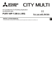
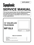
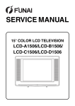
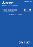
1
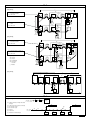
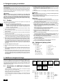
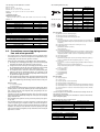
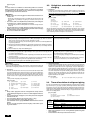
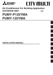
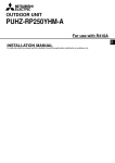
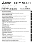
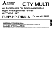
Air-Conditioners For Building Application HEAT SOURCE UNIT PQRY-P400·500YSGM-A INSTALLATION MANUAL For safe and correct use, please read this installation manual thoroughly before installing the air-conditioner unit. I E F D GB For use with R410A MANUEL D’INSTALLATION NL INSTALLATIONSHANDBUCH Zum sicheren und ordnungsgemäßen Gebrauch der Klimageräte das Installationshandbuch gründlich durchlesen. MANUAL DE INSTALACIÓN Para un uso seguro y correcto, lea detalladamente este manual de instalación antes de montar la unidad de aire acondicionado. P Veuillez lire le manuel d’installation en entier avant d’installer ce climatiseur pour éviter tout accident et vous assurer d’une utilisation correcte. MANUAL DE INSTALAÇÃO Para segurança e utilização correctas, leia atentamente este manual de instalação antes de instalar a unidade de ar condicionado. RU INSTALLATIEHANDLEIDING Voor een veilig en juist gebruik moet u deze installatiehandleiding grondig doorlezen voordat u de airconditioner installeert. GR MANUALE DI INSTALLAZIONE Per un uso sicuro e corretto, leggere attentamente questo manuale di installazione prima di installare il condizionatore d’aria. РУКОВОДСТВО ПО УСТАНОВКЕ Для осторожного и правильного использования прибора необходимо тщательно ознакомиться с данным руководством по установке до выполнения установки кондиционера. MONTAJ ELK‹TABI Emniyetli ve do¤ru biçimde nas›l kullan›laca¤›n› ö¤renmek için lütfen klima cihaz›n› monte etmeden önce bu elkitab›n› dikkatle okuyunuz. TR E°XEIPI¢IO O¢H°IøN E°KATA™TA™H™ °È· ·ÛÊ¿ÏÂÈ· Î·È ÛˆÛÙ‹ ¯Ú‹ÛË, ·Ú·Î·Ï›ÛÙ ‰È·‚¿ÛÂÙ ÚÔÛ¯ÙÈο ·˘Ùfi ÙÔ ÂÁ¯ÂÈÚ›‰ÈÔ ÂÁηٿÛÙ·Û˘ ÚÈÓ ·Ú¯›ÛÂÙ ÙËÓ ÂÁηٿÛÙ·ÛË Ù˘ ÌÔÓ¿‰·˜ ÎÏÈÌ·ÙÈÛÌÔ‡. 5 6.2 [Fig. 5.0.1] [Fig. 6.2.1] < = 40° <A> >8m = (10) *1 550 >8m = B C 600 A D 400 990 990 E 6 6.1 400 990 <B> D <A> 45 45 900 45 C D 990 <B> 900 (1254) 602 D 602 550 45 45 602 570 550 900 990 16 C D <A> Side-by-side installation <B> Back-to-back installation Heat exchanger unit B Compressor unit C 4-ø14 (Anchoring hole) D (Top view) *1 Select an installation site that is level and free from vibrations so that the side panels of the units do not rub against each other. Select an installation site that allows the fixation of the units to the floor. [Fig. 6.1.2] 2 A Piping space (for side piping) B Heat exchanger unit C Compressor unit D Service space (front side) E (Top view) F Piping space *2 F 400 <A> Side-by-side installation <B> Back-to-back installation *1 A E 990 E (1254) (50) *2 570 400 B A C 45 A B C 16 45 570 B F 16 A 550 (50) *2 C 550 990 900 550 990 1990 (10) *1 400 45 *2 600 [Fig. 6.1.1] E Anti-vibration pad etc. F Concrete base Select an installation site that is level and free from vibrations so that the side panels of the units do not rub against each other. Select an installation site that allows the fixation of the units to the floor. 6.2 [Fig. 6.2.2] <A> <A> Side-by-side installation <B> Sample back-to-back installation 400 G Piping space (for top piping) H Piping space (for side piping) I Heat exchanger unit J Compressor unit K Field-installed pipes Bypass pipe ø9.52 (Flare + Brazed) High press pipe ø19.05 (Flare + Brazed) Low press pipe ø25.4 (Flange + Brazed) Connecting wire between heat exchanger unit and compressor unit (External heater adapter*) Control signal wire (connector, on-site connection) * If the space between the heat exchanger unit and compressor unit exceeds 1.5 m (the length of the standard supplied external heater adapter), an optional external heater adapter (available in 5m or10m) is necessary. L 990 G I J H M (Front view) N Service space (Heat exchanger unit side) O Service space (Compressor unit side) P Piping space Q Pipe/wire output port R (Side view) *1 Select an installation site that is level and free from vibrations so that the side panels of the units do not rub against each other. Select an installation site that allows the fixation of the units to the floor. BV5 BV3 BV4 K <B> L* M 400 (1254) 990 400 *2 (10) *1 990 G I 400 G J J P N H O BV5 BV3 BV4 600 602 602 600 (50) *2 L Q R 7 M 7.1 7.4 [Fig. 7.1.1] [Fig. 7.4.1] Side piping D Top piping E B A G A E D C C B F TB8 F G 4 J I 63PW 3 A B J I H H H H A Water circulation pipe F Y-type strainer B Close valve G Water inlet C Close valve H Drain pipe D Water outlet I Heat exchanger unit E Refrigerant piping J Compressor unit A Short-circuit wire (Connected before delivery from manufacturer) B Pump interlock circuit connection 3 8 8.2 [Fig. 8.2.1] A B D D E C A D C g h E E No.7 No.7 A Heat exchanger unit B Compressor unit C BC controller (main) D BC controller (sub) E indoor unit (20 ~ 140) F indoor unit (200, 250) C, D a b E E No.1 No.2 (mm) Ì High press. gas pipe ø15.88 ø19.05 ø19.05 B c d E E No.3 No.4 e ~ 200 201 ~ 300 301 ~ 350 f E F No.5 No.6 Ó Low press. gas pipe ø19.05 ø22.2 ø28.58 ¬ Liquid pipe ø9.52 ø12.7 ø12.7 E A Å Heat source model P400 P500 ı High press. side ø22.2 ø22.2 B Î Total capacity of indoor units ~ 140 141 ~ 200 Ô High press pipe ø19.05 (mm) Ç Low press. side ø28.58 ø28.58 ‰ Liquid line ø9.52 ø9.52 a, b, c, d, e, f, g, h (mm) ˜ Model number 20,25,32,40,50 63,71,80,100,125,140 200 250 (mm) Ï Gas line ø15.88 ø19.05 9 Ò Bypass pipe ø9.52 Low press pipe ø28.58 ‰ Liquid line ø6.35 ø9.52 ø9.52 ø9.52 Ï Gas line ø12.7 ø15.88 ø19.05 ø22.2 9.2 [Fig. 9.2.1] [Fig. 9.2.2] <A> [Ball valve (Low press. side/flanged type)] A 3 <C> This figure shows the valve in the fully open state. E 1 <B> [Ball valve (High press. side/flanged type)] E B B O O B S O S S G A Close-packed packing B Hollow packing A A C F C D I H A Valve stem B Stopper pin C Packing (Accessory) D Connecting pipe (Accessory) E Open (Operate slowly) F Cap G Service port H ø22.2 (PQRY-P400) ø22.2 (PQRY-P500) I ø28.58 (PQRY-P400) ø28.58 (PQRY-P500) J Field piping J [Fig. 9.2.3] [Fig. 9.2.4] A A Heat exchanger unit B Compressor unit C Low press pipe (BC controller side ø28.58) D High press pipe (BC controller side ø22.2) E Heat exchanger unit – Compressor unit connection pipe (ø28.58 Flange + Brazed) F Heat exchanger unit – Compressor unit connection pipe (ø19.05 Flare + Brazed) G Heat exchanger unit – Compressor unit connection pipe (ø9.52 Flare + Brazed) B I H H Ball valve C 4 D G FE I External heater adapter (3-wire) 9.3 [Fig. 9.3.1] [Fig. 9.3.2] D N F B B F L LO A O HI E I H <A> HI D G C B H I C LO A C K G E <B> J M K J L A Nitrogen gas G Low press. pipe B To indoor unit H High press. pipe A System analyzer J Valve B Lo knob K C System analyzer I R410A cylinder Heat source unit C Hi knob L D Lo knob Scale J Service port D Ball valve (Heat exchanger unit side) M E Vacuum pump Hi knob K Heat exchanger unit E Low press. pipe N F To indoor unit Ball valve L Compressor unit F High press. pipe O Heat source unit G Service port H Three-way joint I Valve <A> Open <B> Closed [Fig. 9.3.3] A B A : Syphon pipe In case of the cylinder having no syphon pipe. 9.4 [Fig. 9.4.1] B [Fig. 9.4.2] A [Fig. 9.4.3] B A C C D E E E D A B E D A Steel wire B Piping A High press. pipe D Finishing tape C Asphaltic oily mastic or asphalt B Low press. pipe E Insulator D Heat insulation material A C Electric wire E Outer covering B [Fig. 9.4.4] <A> Inner wall (concealed) AB <B> Outer wall C <C> Outer wall (exposed) <D> Floor (waterproofing) D D A B EB F <E> Roof pipe shaft <F> Penetrating portion on fire limit and boundary wall I G J D B I A Sleeve G Sleeve with edge B Heat insulating material H Lagging material C Lagging I Mortar or other incombustible caulking D Caulking material J Incombustible heat insulation material E Band F Waterproofing laye G B H F A 1m 1m 5 10 10.2 [Fig. 10.2.1] L1 L2 L3 N TB1 A M1M2 TB3 C M1M2 S TB7 A Power source B Transmission line C Earth screw B [Fig. 10.2.2] C E D <A> D <B> A <C> B CN103B CN102B CN102A CN103A CN102B <D> CN103B <E> <G> CN101B <F> CN101B C CN101A <I> CN101A F A Heat exchanger unit B Compressor unit C Cable clamp (power supply line) D Cable clamp (control line) E Control cable F Power supply cable <A> <B> <C> <D> <E> <F> <G> <H> <I> Enlarged view of connector section Heat exchanger unit side Compressor unit side CN102B (For power supply line) CN103B (For control line) CN101B (For power supply line) CN102A (For power supply line) CN103A (For control line) CN101A (For power supply line) *1 CN104A is not used for the WR2 models. [Fig. 10.2.3] <A> A B <A> Compressor unit 6 CN103A CN102A A Cable clamp for power supply cable B Cable clamp for transmission cable <H> CN104A (*1) 10.3 L1 [Fig. 10.3.1] CN40 IC IC (01) (02) BC (51) (52) M1M2 S TB3 M1M2 TB5 M1M2 S (55) M1M2 S TB5 M1M2 S IC (05) (06) TB5 M1M2 S r1 M1M2 S TB7 IC BS r2 <B> SW2-1:ON C A OC <A> Change the jumper connector from CN41 to CN40 TB5 M1M2 S r3 L2 D <C> Keep the jumper connector on CN41 <B> SW2-1:ON A B A B A B (101) (105) (155) RC RC RC L3 OC CN40 BC (53) (54) M1M2 S TB3 M1M2 IC IC IC (03) (04) (07) TB5 M1M2 S TB5 M1M2 S TB5 M1M2 S L5 M1M2 S TB7 E L4 L6 System controller r4 M1M2S A B (104) [Fig. 10.3.2] RC B L1 CN40 IC BC (51) M1M2 S c2 TB5 M1M2 S TB15 1 2 (02) TB5 M1M2 S IC BS M1M2 S TB15 1 2 IC c2 (05) (55) TB5 M1M2 S TB15 1 2 c1 c1 TB3 M1M2 IC (01) (52) M1M2 S TB7 C A OC <B> SW2-1:ON c3 D L2 <C> Keep the jumper connector on CN41 <B> SW2-1:ON B Group 4 C Group 5 D Shielded wire E Sub remote controller CN40 (54) M1M2 S TB7 M1M2 S TB3 M1M2 c4 A B A B A B MA MA E L4 BC (53) TB15 1 2 IC IC IC (03) (04) (07) TB5 M1M2 S TB15 1 2 TB5 M1M2 S TB15 1 2 System controller TB5 M1M2 S TB15 1 2 c1 Group 1 L6 A TB5 M1M2 S MA L3 OC (06) c3 <A> Change the jumper connector from CN41 to CN40 M1M2 S ( ): Address A B MA B [Fig. 10.3.3] L8 L1 L2 L3 L5 OC L6 Ground BC TB3 M1M2 IC TB5 M1M2 S RP IC TB2 TB3 A B S A B S TB5 M1M2 S TB5 M1M2 S IC TB5 M1M2 S r1 r1 L7 L4 M1M2 S IC A B A B RC RC N1 N2 10.4 [Fig. 10.4.1] A F B 3 N~380 - 415 V L1, L2, L3, N, PE A Switch (breakers for wiring and current leakage) B Heat source unit (Compressor unit side) C BC controller (main) D C' BC controller (sub) D Pull box E Indoor unit F Breakers for current leakage C' C F A ~220 - 240 V L, N, PE E E E E 7 Contents 1. Safety precautions ...................................................................................... 8 1.1. Before installation and electric work .......................................... 8 1.2. Precautions for devices that use R410A refrigerant .................. 8 1.3. Before getting installed .............................................................. 9 1.4. Before installation electrical work .............................................. 9 1.5. Before starting the test run ........................................................ 9 2. About the product ....................................................................................... 9 3. Specifications .............................................................................................. 9 4. Confirmation of parts attached ................................................................. 10 5. Lifting method ........................................................................................... 10 6. Installation of unit and service space ........................................................ 10 6.1. Installation ............................................................................... 10 6.2. Service space .......................................................................... 10 7. Water pipe installation ............................................................................... 11 7.1. Precautions during installation ................................................ 11 7.2. Insulation installation ............................................................... 11 7.3. Water processing and water quality control ............................. 11 7.4. Pump interlock ......................................................................... 11 8. Refrigerant piping installation ................................................................... 8.1. Caution .................................................................................... 8.2. Refrigerant piping system ........................................................ 9. Additional refrigerant charge ..................................................................... 9.1. Calculation of additional refrigerant charge ............................. 9.2. Precautions concerning piping connection and valve operation ........................................................................ 9.3. Airtight test, evacuation, and refrigerant charging ................... 9.4. Thermal insulation of refrigerant piping ................................... 10. Wiring ........................................................................................................ 10.1. Caution .................................................................................... 10.2. Control box and connecting position of wiring ......................... 10.3. Wiring transmission cables ...................................................... 10.4. Wiring of main power supply and equipment capacity ............ 11. Test run ..................................................................................................... 11.1. The following phenomena do not represent trouble (emergency) ............................................................................ 12. Information on rating plate ........................................................................ 12 12 12 12 12 13 14 14 15 15 15 16 17 18 18 18 GB 1. Safety precautions 1.1. Before installation and electric work D s Before installing the unit, make sure you read all the “Safety precautions”. s The “Safety precautions” provide very important points regarding safety. Make sure you follow them. • • F Symbols used in the text Warning: • Describes precautions that should be observed to prevent danger of injury or death to the user. E Caution: Describes precautions that should be observed to prevent damage to the unit. • Symbols used in the illustrations I : Indicates an action that must be avoided. • : Indicates that important instructions must be followed. : Indicates a part which must be grounded. NL : Beware of electric shock. (This symbol is displayed on the main unit label.) <Color: yellow> Warning: P Carefully read the labels affixed to the main unit. GR • • RU • • Warning: • • TR • • • • • • Ask the dealer or an authorized technician to install the air conditioner. - Improper installation by the user may result in water leakage, electric shock, or fire. Install the unit in a place that can withstand its weight. - Inadequate strength may cause the unit to fall down, resulting in injuries. Use the specified cables for wiring. Make the connections securely so that the outside force of the cable is not applied to the terminals. - Inadequate connection and fastening may generate heat and cause a fire. Prepare for rain and other moisture and earthquakes and install the unit at the specified place. - Improper installation may cause the unit to topple over and result in injury. Always use an filter and other accessories specified by Mitsubishi Electric. - Ask an authorized technician to install the accessories. Improper installation by the user may result in water leakage, electric shock, or fire. Never repair the unit. If the air conditioner must be repaired, consult the dealer. - If the unit is repaired improperly, water leakage, electric shock, or fire may result. If refrigerant gas leaks during installation work, ventilate the room. - If the refrigerant gas comes into contact with a flame, poisonous gases will be released. Install the air conditioner according to this Installation Manual. - If the unit is installed improperly, water leakage, electric shock, or fire may result. Have all electric work done by a licensed electrician according to “Electric Facility Engineering Standard” and “Interior Wire Regulations”and the instructions given in this manual and always use a special circuit. 8 • - If the power source capacity is inadequate or electric work is performed improperly, electric shock and fire may result. Securely install the heat source unit terminal cover (panel). - If the terminal cover (panel) is not installed properly, dust or water may enter the heat source unit and fire or electric shock may result. When installing and moving the air conditioner to another site, do not charge it with a refrigerant different from the refrigerant (R410A) specified on the unit. - If a different refrigerant or air is mixed with the original refrigerant, the refrigerant cycle may malfunction and the unit may be damaged. If the air conditioner is installed in a small room, measures must be taken to prevent the refrigerant concentration from exceeding the safety limit even if the refrigerant should leak. - Consult the dealer regarding the appropriate measures to prevent the safety limit from being exceeded. Should the refrigerant leak and cause the safety limit to be exceeded, hazards due to lack of oxygen in the room could result. When moving and reinstalling the air conditioner, consult the dealer or an authorized technician. - If the air conditioner is installed improperly, water leakage, electric shock, or fire may result. After completing installation work, make sure that refrigerant gas is not leaking. - If the refrigerant gas leaks and is exposed to a fan heater, stove, oven, or other heat source, it may generate noxious gases. Do not reconstruct or change the settings of the protection devices. - If the pressure switch, thermal switch, or other protection device is shorted and operated forcibly, or parts other than those specified by Mitsubishi Electric are used, fire or explosion may result. To dispose of this product, consult your dealer. The installer and system specialist shall secure safety against leakage according to local regulation or standards. - Following standards may be applicable if local regulation are not available. Pay a special attention to the place, such as a basement, etc. where refrigeration gas can stay, since refrigeration is heavier than the air. 1.2. Precautions for devices that use R410A refrigerant Caution: • • • • Do not use the existing refrigerant piping. - The old refrigerant and refrigerator oil in the existing piping contains a large amount of chlorine which may cause the refrigerator oil of the new unit to deteriorate. - R410A is a high-pressure refrigerant and can cause the existing piping to burst. Use refrigerant piping made of phosphorus deoxidized copper and copper alloy seamless pipes and tubes. In addition, be sure that the inner and outer surfaces of the pipes are clean and free of hazardous sulphur, oxides, dust/dirt, shaving particles, oils, moisture, or any other contaminant. - Contaminants on the inside of the refrigerant piping may cause the refrigerant residual oil to deteriorate. Store the piping to be used during installation indoors and keep both ends of the piping sealed until just before brazing. (Store elbows and other joints in a plastic bag.) - If dust, dirt, or water enters the refrigerant cycle, deterioration of the oil and compressor trouble may result. Use ester oil, ether oil or alkylbenzene (small amount) as the refrigerator oil to coat flares and flange connections. - The refrigerator oil will degrade if it is mixed with a large amount of mineral oil. • • • 1.3. Before getting installed Caution: • • • • • • Do not install the unit where combustible gas may leak. - If the gas leaks and accumulates around the unit, an explosion may result. Do not use the air conditioner where food, pets, plants, precision instruments, or artwork are kept. - The quality of the food, etc. may deteriorate. Do not use the air conditioner in special environments. - Oil, steam, sulfuric smoke, etc. can significantly reduce the performance of the air conditioner or damage its parts. When installing the unit in a hospital, communication station, or similar place, provide sufficient protection against noise. - The inverter equipment, private power generator, high-frequency medical equipment, or radio communication equipment may cause the air conditioner to operate erroneously, or fail to operate. On the other hand, the air conditioner may affect such equipment by creating noise that disturbs medical treatment or image broadcasting. Do not install the unit on a structure that may cause leakage. - When the room humidity exceeds 80 % or when the drain pipe is clogged, condensation may drip from the indoor unit. Perform collective drainage work together with the heat source unit, as required. 1.5. Before starting the test run Caution: • • • 1.4. Before installation electrical work • Caution: • • Ground the unit. - Do not connect the ground wire to gas or water pipes, lightning rods, or telephone ground lines. Improper grounding may result in electric shock. The reverse phase of L lines (L1, L2, L3) can be detected (Error cord: 4103), but the reverse phase of L lines and N line can be not be detected. - The some electric parts should be damaged when power is supplied under the miss wiring. GB • D • • F • • • • Turn on the power at least 12 hours before starting operation. - Starting operation immediately after turning on the main power switch can result in severe damage to internal parts. Keep the power switch turned on during the operational season. Do not touch the switches with wet fingers. - Touching a switch with wet fingers can cause electric shock. Do not touch the refrigerant pipes during and immediately after operation. - During and immediately after operation, the refrigerant pipes are may be hot and may be cold, depending on the condition of the refrigerant flowing through the refrigerant piping, compressor, and other refrigerant cycle parts. Your hands may suffer burns or frostbite if you touch the refrigerant pipes. Do not operate the air conditioner with the panels and guards removed. - Rotating, hot, or high-voltage parts can cause injuries. Do not turn off the power immediately after stopping operation. - Always wait at least five minutes before turning off the power. Otherwise, water leakage and trouble may occur. Do not touch the surface of the compressor during servicing. - If unit is connected to the supply and not running, crank case heater at compressor is operating. E • • Install the power cable so that tension is not applied to the cable. - Tension may cause the cable to break and generate heat and cause a fire. Install a leak circuit breaker, as required. - If a leak circuit breaker is not installed, electric shock may result. Use power line cables of sufficient current carrying capacity and rating. - Cables that are too small may leak, generate heat, and cause a fire. Use only a circuit breaker and fuse of the specified capacity. - A fuse or circuit breaker of a larger capacity or a steel or copper wire may result in a general unit failure or fire. Do not wash the air conditioner units. - Washing them may cause an electric shock. Be careful that the installation base is not damaged by long use. - If the damage is left uncorrected, the unit may fall and cause personal injury or property damage. Install the drain piping according to this Installation Manual to ensure proper drainage. Wrap thermal insulation around the pipes to prevent condensation. - Improper drain piping may cause water leakage and damage to furniture and other possessions. Be very careful about product transportation. - Only one person should not carry the product if it weighs more than 20 kg. - Some products use PP bands for packaging. Do not use any PP bands for a means of transportation. It is dangerous. - When transporting the heat source unit, support it at the specified positions on the unit base. Also support the heat source unit at four points so that it cannot slip side ways. Safely dispose of the packing materials. - Packing materials, such as nails and other metal or wooden parts, may cause stabs or other injuries. - Tear apart and throw away plastic packaging bags so that children will not play with them. If children play with a plastic bag which was not torn apart, they face the risk of suffocation. I • • NL • Use liquid refrigerant to fill the system. - If gas refrigerant is used to seal the system, the composition of the refrigerant in the cylinder will change and performance may drop. Do not use a refrigerant other than R410A. - If another refrigerant (R22, etc.) is mixed with R410A, the chlorine in the refrigerant may cause the refrigerator oil to deteriorate. Use a vacuum pump with a reverse flow check valve. - The vacuum pump oil may flow back into the refrigerant cycle and cause the refrigerator oil to deteriorate. Do not use the following tools that are used with conventional refrigerants. (Gauge manifold, charge hose, gas leak detector, reverse flow check valve, refrigerant charge base, refrigerant recovery equipment) - If the conventional refrigerant and refrigerator oil are mixed in the R410A, the refrigerant may deteriorated. - If water is mixed in the R410A, the refrigerator oil may deteriorate. - Since R410A does not contain any chlorine, gas leak detectors for conventional refrigerants will not react to it. Do not use a charging cylinder. - Using a charging cylinder may cause the refrigerant to deteriorate. Be especially careful when managing the tools. - If dust, dirt, or water gets in the refrigerant cycle, the refrigerant may deteriorate. P • This unit uses R410A-type refrigerant • Piping for systems using R410A may be different from that for systems using conventional refrigerant because the design pressure in systems using R410A is higher. Refer to Data Book for more information. • • Some of the tools and equipment used for installation with systems that use other types of refrigerant cannot be used with the systems using R410A. Refer to Data Book for more information. Do not use the existing piping, as it contains chlorine, which is found in conventional refrigerating machine oil and refrigerant. This chlorine will deteriorate the refrigerant machine oil in the new equipment. The existing piping must not be used as the design pressure in systems using R410A is higher than that in the systems using other types of refrigerant and the existing pipes may burst. RU • Net weight TR 3. Specifications PQRY-P400YSGM-A 50 dB <A> Model Noise level Compressor unit Heat exchanger unit Allowable pressure Refrigerant (Compressor unit side only) Total capacity Indoor units Model / Quantity Operation temperature GR 2. About the product PQRY-P500YSGM-A 53 dB <A> PQY-P01YGM-A: 208 kg PQRY-P400YGM-A: 232 kg PQRY-P500YGM-A: 236 kg HP: 4.15 MPa, LP: 2.21 MPa R410A: 12.0 kg 50 ~ 150 % P20 ~ P250 / 1 ~ 24 Water temperature: 10˚C ~ 45˚C P20 ~ P250 / 1 ~ 24 Note.1 Note 1. When the total capacity of indoor units exceeds 130% of heat source units capacity, the operating temperature range of circulating water is 15˚C ~ 45˚C 9 4. Confirmation of parts attached Model Model PQY-P01YGM-A PQRY-P400/P500YGM-A PQY-P01YGM-A PQRY-P400/P500YGM-A 1 Connecting pipe for heat exchanger unit (Low press side ø28.58) – 1 pc. (*) 5 Connecting pipe (Compressor unit - Heat exchanger unit ø19.05) 1 pc. 1 pc. 2 Connecting pipe (Compressor unit - Heat exchanger unit ø28.58) 1 pc. (*) 1 pc. 3 Connecting pipe for heat exchanger unit (High press side ø22.2) – 1 pc. (*) 4 Connecting pipe (Compressor unit - Heat exchanger unit ø9.52) 1 pc. 1 pc. 6 Packing (inside ø23, outside ø35) 7 Bushing (ø27) 8 Bushing (ø38) 1 pc. 2 pcs. 1 pc. – 1 pc. – 9 External heater adapter (3-wire) Model 1 pc. – PQY-P01YGM-A PQRY-P400/P500YGM-A * Fixed with the unit GB 5. Lifting method [Fig. 5.0.1] (P.2) 6. Installation of unit and service space 6.1. Installation 6.2. Service space • • Using the anchoring holes shown below, firmly bolt the unit to the base. [Fig. 6.1.1] (P.2) E F D Caution: Be very careful when carrying the product. - Do not have only one person to carry product if it is more than 20 kg. - PP bands are used to pack some products. Do not use them as a mean for transportation because they are dangerous. - Tear plastic packaging bag and scrap it so that children cannot play with it. Otherwise plastic packaging bag may suffocate children to death. - When carrying the heat source unit, be sure to support it at four points. Carrying with 3-point support may make the heat source unit unstable, resulting in it falling. <A> Side-by-side installation Please allow for the following service spaces after installation. (All servicing can be performed from the front of the unit) [Fig. 6.2.1] (P.2) <B> Back-to-back installation <A> Side-by-side installation Heat exchanger unit B Compressor unit <B> Back-to-back installation C 4-ø14 (Anchoring hole) D (Top view) A Piping space (for side piping) *1 Select an installation site that is level and free from vibrations so that the side panels of the units do not rub against each other. B Heat exchanger unit C Compressor unit Select an installation site that allows the fixation of the units to the floor. D Service space (front side) Bases and anti-vibration E (Top view) • Be sure to install unit in a place strong enough to withstand its weight. If the base is unstable, reinforce with a concrete base. F Piping space *1 • The unit must be anchored on a level surface. Use a level to check after installation. Select an installation site that is level and free from vibrations so that the side panels of the units do not rub against each other. *2 Select an installation site that allows the fixation of the units to the floor. I A P NL *2 • Anti-vibration pads must be placed under the base of the unit. • If the unit is installed near a room where noise is a problem, using an antivibration stand on the base of the unit is recommended. GR RU F Concrete base Warning: • • • TR Anti-vibration pad etc. • Be sure to install unit in a place strong enough to withstand its weight. Any lack of strength may cause unit to fall down, resulting in a personal injury. Have installation work in order to protect against earthquake. Any installation deficiency may cause unit to fall down, resulting in a personal injury. In the case of a side-by-side installation of a compressor unit and a heat exchanger unit, leave a space of at least 10mm between them. When they are installed too closely together, they may rub against each other and generate noise. In the case of a back-to-back installation of a compressor unit and a heat exchanger unit, leave a space of at least 50mm between them. If they are installed to closely together, there may not be enough space for using the tools to anchor the units to the base. 10 <A> Side-by-side installation <B> Sample back-to-back installation [Fig. 6.1.2] (P.2) E [Fig. 6.2.2] (P.3) G Piping space (for top piping) H Piping space (for side piping) I Heat exchanger unit J Compressor unit K Field-installed pipes Bypass pipe ø9.52 (Flare + Brazed) High press pipe ø19.05 (Flare + Brazed) Low press pipe ø25.4 (Flange + Brazed) Connecting wire between heat exchanger unit and compressor unit (External heater adapter*) Control signal wire (connector, on-site connection) * If the space between the heat exchanger unit and compressor unit exceeds 1.5 m (the length of the standard supplied external heater adapter), an optional external heater adapter (available in 5m or10m) is necessary. L M (Front view) N Service space (Heat exchanger unit side) O Service space (Compressor unit side) P Piping space Q Pipe/wire output port R (Side view) *1 Select an installation site that is level and free from vibrations so that the side panels of the units do not rub against each other. *2 Select an installation site that allows the fixation of the units to the floor. 7. Water pipe installation City Multi WR2 Series pipes are similar to other air-conditioning pipes, however, please observe the following precautions during installation. sealant particles, or rust, do not enter the pipes. • There is a water vent plug in the center of the heat exchanger water inlet head at the middle of the unit. Use this for maintenance, etc. In addition, do not allow any of the unit’s electrical parts (such as the solenoid valve coil or compressor power supply) to become wet. • Install a back flow-prevention valve on the pump and a flexible joint to prevent excess vibration. • Use a sleeve to protect the pipes where they go through a wall. • Use metal fittings to secure the pipes, and install them so that they have maximum protection against breakage and bending. • Do not confuse the water intake and outlet valves. • This unit doesn’t have any heater to prevent freezing within tubes. When the water flow is stopped on low ambient, take out the water from tubes. • The unused knockout holes should be closed and the opening of refrigerant pipes, water pipes, power source and transmission wires should be filled with putty and so on to prevent from rain. (field construction) pH (25˚C) Electric conductivity (mS/m) (25˚C) (µ s/cm) (25˚C) Chloride ion (mg Cl-/r) (mg SO42-/r) Standard Sulfate ion Acid consumption (pH4.8) items (mg CaCO3/r) Total hardness (mg CaCO3/r) Calcium hardness (mg CaCO3/r) Ionic silica (mg SiO2/r) Iron (mg Fe/r) ReferCopper (mg Cu/r) ence items Sulfide ion (mg S2-/r) 70 or less 50 or less 30 or less 1.0 or less 1.0 or less not to be detected + Ammonium ion (mg NH4 /r) 0.3 or less Residual chlorine (mg Cl/r) 0.25 or less Free carbon dioxide (mg CO2/r) 0.4 or less Ryzner stability index – Example of heat source unit installation (using left piping) [Fig. 7.1.1] (P.3) A Water circulation pipe B Close valve C Close valve D Water outlet E Refrigerant piping F Y-type strainer G Water inlet H Drain pipe I Heat exchanger unit J Compressor unit 7.2. Insulation installation With City Multi WR2 Series piping, as long as the temperature range of the circulating water is kept to average temperatures year-round (30°C in the summer, 20°C in the winter), there is no need to insulate or otherwise protect indoor piping from exposure. You should use insulation in the following situations: • Any heat source piping. • Indoor piping in cold-weather regions where frozen pipes are a problem. • When air coming from the outside causes condensation to form on piping. • Any drainage piping. 7.3. Water processing and water quality control To preserve water quality, use the closed type of cooling tower for WR2. When the circulating water quality is poor, the water heat exchanger can develop scales, leading to a reduction in heat-exchange power and possible corrosion of the heat exchanger. Please pay careful attention to water processing and water quality control when installing the water circulation system. • Removal of foreign objects or impurities within the pipes. During installation, be careful that foreign objects, such as welding fragments, 50 or less GB • Items Lower mid-range Tendency temperature water system Recirculating ScaleMake-up water Corrosive forming water [20<T=60˚C] 7.0 ~ 8.0 7.0 ~ 8.0 30 or less 30 or less [300 or less] [300 or less] 50 or less 50 or less 50 or less 50 or less 50 or less D Compressed water may form in the low-temperature sections of heat source unit. Use a drainage pipe connected to the drain valve at the base of the unit to drain the water. 70 or less 50 or less 30 or less 0.3 or less 0.1 or less not to be detected 0.1 or less 0.3 or less 4.0 or less – F • 2 Water quality standard E Install a suitable air vent on the water pipe. After sending water through the pipe, be sure to vent the excess air. Reference : Guideline of Water Quality for Refrigeration and Air Conditioning Equipment. (JRA GL02E-1994) 3 Please consult with a water quality control specialist about water quality control methods and water quality calculations before using anti-corrosive solutions for water quality management. 4 When replacing a previously installed air conditioning device (even when only the heat exchanger is being replaced), first conduct a water quality analysis and check for possible corrosion. Corrosion can occur in cold-water systems even if there has been no prior signs of corrosion. If the water quality level has dropped, please adjust water quality sufficiently before replacing the unit. 7.4. Pump interlock I • NL To insure easy maintenance, inspection, and replacement of the unit, use a proper joint, valve, etc. on the water intake and outlet port. In addition, be sure to install a strainer on the water intake pipe. (In order to maintain the heat source unit, a strainer on the circulating water inlet is necessary.) * An example of the heat source unit installation is shown in the diagram below. P Use the reverse-return method to insure proper pipe resistance to each unit. • The heat source unit may become damaged if it is operated with no water circulating through the pipes. Be sure to interlock unit operation and the water-circuit pump. Use the terminal blocks for interlocking (TB8-3, 4) that can be found on the unit. In the case of a pump interlock circuit signal connection to the TB8-3, 4, remove the short-circuit wire. Also, to prevent mistaken error detection, resulting from a poor connection, in the pressure valve 63PW, use a low maintained current of 5mA or less. GR • Water Quality Processing 1 Depending on the quality of the cold-temperature water used in the airconditioner, the copper piping of the heat exchanger may become corroded. We recommend regular water quality processing. Cold water circulation systems using open heat storage tanks are particularly prone to corrosion. When using an open-type heat storage tank, install a water-to-water heat exchanger, and use a closed-loop circuit on the air conditioner side. If a water supply tank is installed, keep contact with air to a minimum, and keep the level of dissolved oxygen in the water no higher than 1mg/r. [Fig. 7.4.1] (P.3) A Short-circuit wire (Connected before delivery from manufacturer) B Pump interlock circuit connection RU 7.1. Precautions during installation TR • 11 8. Refrigerant piping installation City Multi WR2 Series is constituted by an end branching system in which the refrigerant piping from heat source unit is branched at BC controller and connected to each indoor unit. The connection method adapted is brazing connection for high pressure pipe and low pressure pipe between heat source unit and BC controller, and flare connection between BC controller and indoor unit. Brazing connection is employed for joint pipe set and branch pipe set. Warning: Always use extreme care to prevent the refrigerant gas from leaking while using fire or flame. If the refrigerant gas comes in contact with a flame from any source, such as a gas stove, it breaks down and generates a poisonous gas which can cause gas poisoning. Never weld in an unventilated room. Always conduct an inspection for gas leakage after installation of the refrigerant piping has been completed. A Residues in commercially available antioxidants may have adverse effects on the equipment. Braze only with non-oxide brazing material. The use of other brazing material may result in compressor damage. (Refer to item 9.2. for detailed information on pipe connections and valve operations.) B Never perform heat source unit piping connection work when it is raining. Warning When installing and moving the unit, do not charge it with refrigerant other than the refrigerant specified on the unit. - Mixing of a different refrigerant, air, etc. may cause the refrigerant cycle to malfunction and result in severe damage. Caution: • 8.1. Caution D GB This unit uses refrigerant R410A. Follow the local regulations on materials and pipe thickness when selecting pipes. 2 Commercially available piping often contains dust and other materials. Always blow it clean with a dry inert gas. 4 Reduce the number of bending portions as much as possible, and make bending radius as big as possible. 5 Always observe the restrictions on the refrigerant piping (such as rated length, the difference between high/low pressures, and piping diameter). Failure to do so can result in equipment failure or a decline in heating/cooling performance. 6 Either a lack or an excess of refrigerant causes the unit to make an emergency stop. Charge the system with an appropriate amount of refrigerant. At such a time, always properly charge the unit. When servicing, always check the notes concerning pipe length and amount of additional refrigerant at both locations, the refrigerant volume calculation table on the back of the service panel and the additional refrigerant section on the labels for the combined number of indoor units. I E F 3 Use care to prevent dust, water or other contaminants from entering the piping during installation. 7 Use liquid refrigerant to fill the system. RU GR P NL 8 Never use refrigerant to perform an air purge. Always evacuate using a vacuum pump. TR • 1 Use the following materials for refrigeration piping. • Material: Use refrigerant piping made of phosphorus deoxidized copper. In addition, be sure that the inner and outer surfaces of the pipes are clean and free of hazardous sulphur, oxides, dust/dirt, shaving particles, oils, moisture, or any other contaminant. 9 Always insulate the piping properly. Insufficient insulation will result in a decline in heating/cooling performance, water drops from condensation and other such problems. 0 When connecting the refrigerant piping, make sure the ball valve of the heat source unit is completely closed (the factory setting) and do not operate it until the refrigerant piping for the heat source and indoor units has been connected, a refrigerant leakage test has been performed and the evacuation process has been completed. • • • • • Use a vacuum pump with a reverse flow check valve. - If the vacuum pump does not have a reverse flow check valve, the vacuum pump oil may flow back into the refrigerant cycle and cause deterioration of the refrigerator oil and other trouble. Do not use the tools shown below used with conventional refrigerant. (Gauge manifold, charge hose, gas leak detector, check valve, refrigerant charge base, vacuum gauge, refrigerant recovery equipment) - Mixing of conventional refrigerant and refrigerator oil may cause the refrigerator oil to deteriorate. - Mixing of water will cause the refrigerator oil to deteriorate. - R410A refrigerant does not contain any chlorine. Therefore, gas leak detectors for conventional refrigerants will not react to it. Manage the tools more carefully than normal. - If dust, dirt, or water gets in the refrigerant cycle, the refrigerator oil will deteriorate. Never use existing refrigerant piping. - The large amount of chlorine in conventional refrigerant and refrigerator oil in the existing piping will cause the new refrigerant to deteriorate. Store the piping to be used during installation indoors and keep both ends of the piping sealed until just before brazing. - If dust, dirt, or water gets into the refrigerant cycle, the oil will deteriorate and the compressor may fail. Do not use a charging cylinder. - Using a charging cylinder may cause the refrigerant to deteriorate. Do not use special detergents for washing piping. 8.2. Refrigerant piping system Connection Example [Fig. 8.2.1] (P.4) Å Heat source model ı High press. side Ç Low press. side Î Total capacity of indoor units ‰ Liquid line Ï Gas line Ì High press. gas pipe Ó Low press. gas pipe ¬ Liquid pipe Ô High press pipe Low press pipe Ò Bypass pipe ˜ Model number A Heat exchanger unit B Compressor unit C BC controller (main) D BC controller (sub) E indoor unit (20 ~ 140) F indoor unit (200, 250) 9. Additional refrigerant charge At the time of shipping, the heat source unit is charged with the refrigerant. As this charge does not include the amount needed for extended piping, additional charging for each refrigerant line will be required on site. In order that future servicing may be properly provided, always keep a record of the size and length of each refrigerant line and the amount of additional charge by writing it in the space provided on the heat source unit. 9.1. Calculation of additional refrigerant charge • Calculate the amount of additional charge based on the length of the piping extension and the size of the refrigerant line. • Use the table to the below as a guide to calculating the amount of additional charging and charge the system accordingly. • If the calculation results in a fraction of less than 0.1 kg, round up to the next 0.1 kg. For example, if the result of the calculation was 21.66 kg, round the result up to 21.7 kg. 12 <Additional Charge> Additional High pressure refrigerant pipe size = charge Total length of ø22.2 × 0.23 High pressure pipe size High pressure pipe size High pressure pipe size + Total length of + Total length of + Total length of ø19.05 × 0.16 ø15.88 × 0.11 ø12.7 × 0.12 (m) × 0.16 (kg/m) (m) × 0.11 (kg/m) (m) × 0.12 (kg/m) (m) × 0.23 (kg/m) (kg) High pressure pipe size + Total length of ø9.52 × 0.06 High pressure pipe size + Total length of ø6.35 × 0.024 (m) × 0.06 (kg/m) Outdoor: 500 Indoor No. 1: No. 2: No. 3: No. 4: No. 5: No. 6: No. 7: No. 8: 40 100 40 32 63 200 32 32 A: B: C: D: ø22.2 ø9.52 ø12.7 ø12.7 + α1 + α2 + α3 (m) × 0.024 (kg/m) 40 m 10 m 10 m 10 m a: b: c: d: e: f: g: h: ø6.35 ø9.52 ø6.35 ø6.35 ø9.52 ø9.52 ø6.35 ø6.35 10 m 5m 10 m 10 m 10 m 10 m 5m 5m At the conditions below: The total length of each liquid line is as follows: ø22.2: A = 40 m ø12.7: C + D = 10 + 10 = 20 m ø9.52: B + b + e + f = 10 + 5 + 10 + 10 = 35 m ø6.35: a + c + d + g + h = 10 + 10 + 10 + 5 + 5 = 40 m flare machining dimension (mm) size in inches ø6.35 ø9.52 ø12.70 ø15.88 ø19.05 1/4" 3/8" 1/2" 5/8" 3/4" outer diameter size in inches ø6.35 ø9.52 ø12.70 ø15.88 ø19.05 1/4" 3/8" 1/2" 5/8" 3/4" A outer diameter Therefore, <Calculation example> Additional refrigerant charge = 40 × 0.23 + 20 × 0.12 + 35 × 0.06 + 40 × 0.024 + 3.0 + 2.0 + 2.0 = 21.7 kg dimension A R410A 9.1 13.2 16.6 19.7 24.0 flare nut size (mm) Value of α1 Total capacity of connecting indoor units to Model 80 Models 81 to 160 Models 161 to 330 Models 331 to 480 Models 481 to 630 Models 631 to 710 Models 711 to 890 α1 1.0 kg 1.5 kg 2.0 kg 2.5 kg 3.0 kg 4.0 kg 5.0 kg B dimension B R410A 17.0 22.0 26.0 29.0 36.0 [Fig. 9.2.2] (P.4) Value of α2 <C> This figure shows the valve in the fully open state. Valve stem [Fully closed at the factory, when connecting the piping, when evacuating, and when charging additional refrigerant. Open fully after the operations above are completed.] B Stopper pin [Prevents the valve stem from turning 90° or more.] C Packing (Accessory) [Manufacturer: Nichiasu corporation] [Type: T/#1991-NF] 9.2. Precautions concerning piping connection and valve operation D Connecting pipe (Accessory) [Use packing and securely install this pipe to the valve flange so that gas leakage will not occur. (Tightening torque:40 N·m) Coat both surfaces of the packing with refrigerating machine oil. (Ester oil, ether oil or alkylbenzene [small amount])] • E Open (Operate slowly) F Cap, copper packing [Remove the cap and operate the valve stem. Always reinstall the cap after operation is completed. (Valve stem cap tightening torque: 23 ~ 27 N·m)] G Service port [Use this port to evacuate the refrigerant piping and add an additional charge at the site. Open and close the port using a double-ended wrench. Always reinstall the cap after operation is completed. (Service port cap tightening torque: 12 ~ 15 N·m)] H ø22.2 (PQRY-P400) ø22.2 (PQRY-P500) I ø28.58 (PQRY-P400) ø28.58 (PQRY-P500) J Field piping • Flange type side connecting pipe is assembled in factory before shipment. 1 For brazing to the connecting pipe with flange, remove the connecting pipe with flange from the ball valve, and braze it outside of the unit. 2 During the time when removing the connecting pipe with flange, remove the seal attached on the rear side of this sheet and paste it onto the flange surface of the ball valve to prevent the entry of dust into the valve. 3 The refrigerant circuit is closed with a round, close-packed packing upon shipment to prevent gas leak between flanges. As no operation can be done under this state, be sure to replace the packing with the hollow packing attached at the piping connection. [Fig. 9.2.3] (P.4) 4 At the mounting of the hollow packing, wipe off dust attached on the flange sheet surface and the packing. Coat refrigerating machine oil (Ester oil, ether oil or alkylbenzene [small amount]) onto both surfaces of the packing. [Fig. 9.2.1] (P.4) • A Heat exchanger unit B Compressor unit C Low press pipe (BC controller side ø28.58) D High press pipe (BC controller side ø22.2) A Close-packed packing E Heat exchanger unit – Compressor unit connection pipe (ø28.58 Flange + Brazed) B Hollow packing F Heat exchanger unit – Compressor unit connection pipe (ø19.05 Flare + Brazed) G Heat exchanger unit – Compressor unit connection pipe (ø9.52 Flare + Brazed) H Ball valve I External heater adapter (3-wire) After evacuation and refrigerant charge, ensure that the handle is fully open. If operating with the valve closed, abnormal pressure will be imparted to the high- or low-pressure side of the refrigerant circuit, giving damage to the compressor, four-way valve, etc. • Determine the amount of additional refrigerant charge by using the formula, and charge refrigerant additionally through the service port after completing piping connection work. • After completing work, tighten the service port and cap securely not to generate gas leak. • Flare machining dimension for systems using R410A is larger than that for systems using other types of refrigerant in order to increase the air tightness. • Refer to the table on the below for flare machining dimensions, and follow the regulations set forth by the local authorities. Seal off the opening of the pipe with a closure material (not supplied) to keep small animals from entering the pipe if that is a concern. • Connect the pipes on the compressor unit and heat exchanger unit on site. Pipe sizes are shown below. Perform piping work according to the instructions in section 9.4 Thermal insulation of refrigerant piping. Appropriate tightening torque by torque wrench: Copper pipe external dia. (mm) ø6.35 ø9.52 ø12.7 ø15.88 ø19.05 Tightening torque (N·m) 14 to 18 35 to 42 50 to 57.5 75 to 80 100 to 140 Tightening angle standard: Pipe diameter (mm) ø6.35, ø9.52 ø12.7, ø15.88 ø19.05 F E Conduct piping connection and valve operation accurately. I • NL The compressor unit is charged with refrigerant at factory shipment, but the heat exchanger unit is not. (The heat exchanger unit is charged with inert gas.) Tightening angle (°) 60 to 90 30 to 60 20 to 35 13 P α3 0 kg 2.0 kg GR PQRY-P400YSGM-A PQRY-P500YSGM-A RU Value of α3 D A GB <B> [Ball valve (High press. side/flanged type)] TR BC controller (main only) BC controller (sub) connected (one) BC controller (sub) connected (two) <A> [Ball valve (Low press. side/flanged type)] α2 0 kg 1.0 kg 2.0 kg [Fig. 9.2.4] (P.4) Note: If a torque wrench is not available, use the following method as a standard: When you tighten the flare nut with a wrench, you will reach a point where the tightening torque will abruptly increase. Turn the flare nut beyond this point by the angle shown in the table above. Caution: • • • I E F D GB • Always remove the connecting pipe from the ball valve and braze it outside the unit. - Brazing the connecting pipe while it is installed will heat the ball valve and cause trouble or gas leakage. The piping, etc. inside the unit may also be burned. Use ester oil, ether oil or alkylbenzene (small amount) as the refrigerating machine oil to coat flares and flange connections. - The refrigerating machine oil will degrade if it is mixed with a large amount of mineral oil. Keep the ball valve closed until refrigerant charging to the pipes to be added on site has been completed. Opening the valve before charging the refrigerant may result in unit damage. Do not use a leak detection additive. NL 1 Airtight test Evacuate the connecting pipes and indoor units through the service port on the ball valve of the heat exchanger unit with a vacuum pump with the ball valve on the compressor unit closed and the ball valve on the heat exchanger open as shown in the figure below. (Be sure to vacuum through the service port on both the liquid and gas pipes.) [Fig. 9.3.1] (P.5) <A> Open <B> Closed A Nitrogen gas B To indoor unit C System analyzer D Lo knob E Hi knob F Ball valve G Low press. pipe H High press. pipe I Heat source unit J Service port K Heat exchanger unit L Compressor unit Observe the following restrictions when conducting an air tightness test to prevent negative effects on the refrigerating machine oil. Also, with nonazeotropic refrigerant (R410A), gas leakage causes the composition to change and affects performance. Therefore, perform the airtightness test cautiously. Airtight test procedure Restriction 1. Nitrogen gas pressurization (1) After pressurizing to the design pressure (4.15 MPa) using nitrogen gas, allow it to stand for about one day. If the pressure does not drop, airtightness is good. However, if the pressure drops, since the leaking point is unknown, the following bubble test may also be performed. (2) After the pressurization described above, spray the flare connection parts, brazed parts, flanges, and other parts that may leak with a bubbling agent (Kyuboflex, etc.) and visually check for bubbles. (3) After the airtight test, wipe off the bubbling agent. • If a flammable gas or air (oxygen) is used as the pressurization gas, it may catch fire or explode. 2. Pressurization using refrigerant gas and nitrogen gas (1) Pressurizing to a gas pressure of approximately 0.2 MPa, pressurize to the design pressure (4.15 MPa) using nitrogen gas. However, do not pressurize at one time. Stop during pressurization and check that the pressure does not drop. (2) Check for gas leaks by checking the flare connection parts, brazed parts, flanges, and other parts which may leak using an R410A compatible electric leak detector. (3) This test may be used together the with bubble type gas leak test. • Do not use a refrigerant other than that indicated on the unit. • Sealing with gas from a cylinder will cause the composition of the refrigerant in the cylinder to change. • Use a pressure gauge, charging hose, and other parts especially for R410A. • An electric leak detector for R22 cannot detect leaks of R410A. • Do not use a haloid torch. (Leaks cannot be detected.) Caution: Only use refrigerant R410A. - The use of other refrigerant such as R22 or R407C, which contains chlorine, will deteriorate the refrigerating machine oil or cause the compressor to malfunction. P 9.3. Airtight test, evacuation, and refrigerant charging 2 Evacuation Evacuate with the ball valve of the heat source unit closed and evacuate both the connection piping and the indoor unit from the service port provided on the ball valve of the heat source unit using a vacuum pump. (Always evacuate from the service port of both the high press pipe and the low press pipe.) After the vacuum reaches 650 Pa [abs], continue evacuation for at least one hour or more. * Never perform air purging using refrigerant. 3 Refrigerant Charging Since the refrigerant used with the unit is nonazerotropic, it must be charged in the liquid state. Consequently, when charging the unit with refrigerant from a cylinder, if the cylinder does not have a syphon pipe, charge the liquid refrigerant by turning the cylinder upside-down as shown in Fig.9.3.3. If the cylinder has a syphon pipe like that shown in the picture on the right, the liquid refrigerant can be charged with the cylinder standing upright. Therefore, give careful attention to the cylinder specifications. If the unit should be charged with gas refrigerant, replace all the refrigerant with new refrigerant. Do not use the refrigerant remaining in the cylinder. [Fig. 9.3.3] (P.5) A Syphon pipe B In case of the cylinder having no syphon pipe. TR RU GR [Fig. 9.3.2] (P.5) A System analyzer Lo knob C Hi knob D Ball valve (Heat exchanger unit side) B E Low press. pipe F High press. pipe G Service port H Three-way joint I Valve J Valve K R410A cylinder L Scale M Vacuum pump N To indoor unit O Heat source unit Note: • Always add an appropriate amount of refrigerant. Also always seal the system with liquid refrigerant. Too much or too little refrigerant will cause trouble. • Use a gauge manifold, charging hose, and other parts for the refrigerant indicated on the unit. • Use a graviometer. (One that can measure down to 0.1 kg.) • Use a vacuum pump with a reverse flow check valve. (Recommended vacuum gauge: ROBINAIR 14830A Thermistor Vacuum Gauge) Also use a vacuum gauge that reaches 65 Pa [abs] or below after operating for five minutes. 9.4. Thermal insulation of refrigerant piping Be sure to give insulation work to refrigerant piping by covering high press. (liquid) pipe and low press. (gas) pipe separately with enough thickness heat-resistant polyethylene, so that no gap is observed in the joint between indoor unit and insulating material, and insulating materials themselves. When insulation work is insufficient, there is a possibility of condensation drip, etc. Pay special attention to insulation work to ceiling plenum. [Fig. 9.4.1] (P.5) A Steel wire B Piping C Asphaltic oily mastic or asphalt D Heat insulation material A E Outer covering B Heat insulation material A Glass fiber + Steel wire Adhesive + Heat - resistant polyethylene foam + Adhesive tape Indoor Vinyl tape Outer Floor exposed Water-proof hemp cloth + Bronze asphalt covering B Heat source Water-proof hemp cloth + Zinc plate + Oily paint Note: • When using polyethylene cover as covering material, asphalt roofing shall not be required. • No heat insulation must be provided for electric wires. 14 [Fig. 9.4.2] (P.5) A High press. pipe B Low press. pipe D Finishing tape E Insulator C Electric wire When filling a gap with mortar, cover the penetration part with steel plate so that the insulation material will not be caved in. For this part, use incombustible materials for both insulation and covering. (Vinyl covering should not be used.) • [Fig. 9.4.3] (P.5) Insulation materials for the pipes to be added on site must meet the following specifications: Penetrations [Fig. 9.4.4] (P.5) <A> Inner wall (concealed) <B> Outer wall <C> Outer wall (exposed) <D> Floor (waterproofing) <E> Roof pipe shaft Thickness Temperature Resistance * Installation of pipes in a high-temperature high-humidity environment, such as the top floor of a building, may require the use of insulation materials thicker than the ones specified in the chart above. * When certain specifications presented by the client must be met, ensure that they also meet the specifications on the chart above. <F> Penetrating portion on fire limit and boundary wall A Sleeve B Heat insulating material C Lagging D Caulking material E Band F Waterproofing laye G Sleeve with edge H Lagging material I Mortar or other incombustible caulking J Incombustible heat insulation material Pipe size ø6.35 ~ 25.4 mm ø28.58 ~ 38.1 mm 10 mm min. 15 mm min. 100 °C min. 5 Never connect the main power source to terminal block of transmission line. If connected, electrical parts will be burnt out. 6 Use 2-core shield cable for transmission line. If transmission lines of different systems are wired with the same multiplecore cable, the resultant poor transmitting and receiving will cause erroneous operations. 7 Only the transmission line specified should be connected to the terminal block for heat source unit transmission. (Transmission line to be connected with indoor unit : Terminal block TB3 for transmission line, Other : Terminal block TB7 for centralized control) Erroneous connection does not allow the system to operate. 8 In the case of connecting with an upper class controller or to conduct group operation in different refrigerant systems, the control line for transmission is required between the heat source units. Connect this control line between the terminal blocks for centralized control. (2-wire line with no polarity) When conducting group operation in different refrigerant systems without connecting to the upper class controller, replace the insertion of the short circuit connector from CN41 of one heat source unit to CN40. 9 Group is set by operating the remote controller. 10.2. Control box and connecting position of wiring <Wiring compressor unit, BC controller unit, and Indoor units> D F <Heat exchanger unit – compressor unit connection> 1. Connect the connectors on the compressor unit and the heat exchanger unit using the wires installed on the compressor unit (External heater adapter). E 4 Give some allowance to wiring for electrical part box of indoor and heat source units, because the box is sometimes removed at the time of service work. 6. Use the terminal block for pump interlock (TB8) when interlocking the unit with the pump in the water circuit. In this case, be sure to remove the short circuit wire on the terminal block for pump interlocking (TB8). Run the cable to TB8 via the same route as the power supply line. 2. The top service panel can be removed by removing the three screws at the top, tilting the panel by pulling the top of it away from the unit body, and pulling it up. 3. The bottom service panel can be removed by first removing the top service panel, then removing the 3 screws at the top, tilting the panel by pulling the top of it away from the unit body, and pulling it up. 4. Wire the units as shown in the figure below. Run the power supply line [0.75mm2] and control line [0.3mm2] separately and at least 5cm away from each other. Keep them out of contact with the pipes. Connect the heat exchanger unit and the compressor unit via 3 of the 4 connectors on each unit. I 3 Be sure to provide designated grounding work to heat source unit. 5. Narrow the opening by using a conduit to keep small animals out. NL 2 Wiring for control (hereinafter referred to as transmission line) shall be (5 cm or more) apart from power source wiring so that it is not influenced by electric noise from power source wiring. (Do not insert transmission line and power source wire in the same conduit.) 4. Fix power source wiring to terminal box by using buffer bushing for tensile force (PG connection or the like). [Fig. 10.2.2] (P.6) A Heat exchanger unit B Compressor unit C Cable clamp (power supply line) D Cable clamp (control line) E Control cable F Power supply cable P 1 Follow ordinance of your governmental organization for technical standard related to electrical equipment, wiring regulations and guidance of each electric power company. 3. Conduit mounting plates (ø27) are being provided. Pass the power supply and transmission wires through the appropriate knock-out holes, then remove the knock-out piece from the bottom of the terminal box and connect the wires. <A> Enlarged view of connector section <B> Heat exchanger unit side GR 10.1. Caution GB 10. Wiring <C> Compressor unit side <D> CN102B (For power supply line) <E> CN103B (For control line) <F> CN101B (For power supply line) <H> CN103A (For control line) <I> CN101A (For power supply line) *1 CN104A is not used for the WR2 models. 5. The length of standard equipped wiring, not including the heat exchanger unit’s and the compressor unit’s internal wiring, is approximately 1.5m. If longer wiring is required, use optional extension wire for water heat source (Available in 5 m and 10 m, not including the unit’s internal wiring). 6. Clamp excess power supply line [0.75mm2] and control line [0.3mm2] separately with the cable clamps on the compressor unit’s side panel. Choose the appropriate size cable clamps for the amount of excess wiring. [Fig. 10.2.3] (P.6) <A> Compressor unit A Cable clamp for power supply cable B Cable clamp for control cable [Fig. 10.2.1] (P.6) A Power source C Earth screw B Transmission line 15 TR 2. Connect the indoor unit transmission line to transmission terminal block (TB3), or connect the wiring between heat source units or the wiring with the central control system to the central control terminal block (TB7). When using shielded wiring, connect shield ground of the indoor unit transmission line to the earth screw ( ) and connect shield ground of the line between heat source units and the central control system transmission line to the shield (S) terminal of the central control terminal block (TB7) shield (S) terminal. In addition, in the case of heat source units whose power supply connector CN41 has been replaced by CN40, the shield terminal (S) of terminal block (TB7) of the central control system should also be connected to the earth screw ( ). Fix the wiring securely in place with the cable strap at the bottom of the terminal block so that the external force if not applied to the terminal block. External force applied to the terminal block may damage the block and short-circuit, ground fault, or fire may result. RU <G>CN102A (For power supply line) 1. The controller box for the BC controller/indoor unit wiring is on the compressor unit. 7. Heat exchanger unit – compressor unit connected cable. Cable name Kind of control cable Cable diameter Maximum wiring length Remarks 2. Remote control cables • Cable 1 Cable 2 Cable 3 Cable 4 *1 8 core cable 12 core cable 12 core cable 6 core cable (unshielded) (unshielded) (unshielded) (unshielded) VCT *2 VCT *2 VCT *3 VCT *3 0.75 mm2 0.75 mm2 0.3 mm2 10 m 0.3 mm2 Remarks Put the cable that connects the heat source units through a conduit tube. Connect both ends of the conduit tube to the unit’s casing. Do not put cable 1 and cable 2 through the same conduit tube with cable 3 and cable 4. • • 1. Wiring transmission cables • Types of transmission cables: Shielding wire CVVS or CPEVS or MVVS • Cable diameter: More than 1.25 mm2 • Maximum wiring length: Within 200 m • Maximum length of transmission lines for centralized control and indoor/outdoor transmission lines (Maximum length via indoor units): 500 m MAX Controller name, symbol and allowable number of controllers. Name Symbol Allowable number of controllers Heat source unit controller OC BC Controller (main) BC One controller for one OC BC Controller (sub) BS Zero, one or two controllers for one OC Transmission booster unit RP Zero or one unit for one OC (*1) Two to twenty four controllers for one OC (*1) Indoor Unit Controller IC Maximum of two per group Remote Controller RC 1 Types of control cables GB MA Remote Controller 2 Wiring examples 10.3. Wiring transmission cables D Sheathed 2-core cable (unshielded) 0.3 to 1.25 mm2 (0.75 to 1.25 mm2)* When 10 m is exceeded, use cable with the same specifications as 1. Wiring transmission cables. Kind of remote control cable Sheathed 2-core cable (unshielded) CVV 0.3 to 1.25 mm2 (0.75 to 1.25 mm2)* Cable diameter Within 200 m Remarks * Connected with simple remote controller. *1 : PQHY-P400, 500 type only *2 : VCT cable is not be lighter than design 245 IEC57. *3 : VCTF cable is not be lighter than design 245 IEC53. F M-NET Remote Controller Kind of remote control cable Cable diameter *1 A transmission booster (RP) may be required depending on the number of connected indoor unit controllers. The maximum length of the wiring between power supply unit for transmission lines (on the transmission lines for centralized control) and each outdoor unit and system controller is 200 m. Example of a group operation system with multiple heat source units (Shielding wires and address setting are necessary.) <Examples of transmission cable wiring> E [Fig. 10.3.1] M-NET Remote Controller (P.7) [Fig. 10.3.2] MA Remote Controller (P.7) [Fig. 10.3.3] Transmission booster unit (P.7) <A> Change the jumper connector from CN41 to CN40. <B> SW2-1:ON I <C> Keep the jumper connector on CN41. A Group 1 B Group 4 C Group 5 D Shielded wire E Sub remote controller ( ): Address NL <Wiring Method and Address Settings> a. Always use shielded wire when making connections between the heat source unit (OC) and the indoor unit (IC), as well for all OC-OC, and IC-IC wiring intervals. b. Use feed wiring to connect terminals M1 and M2 and the earth terminal on the transmission cable terminal block (TB3) of each heat source unit (OC) to terminals M1, M2 and terminal S on the transmission cable block of the indoor unit (IC). P c. Connect terminals 1 (M1) and 2 (M2) on the transmission cable terminal block of the indoor unit (IC) that has the most recent address within the same group to the terminal block on the remote controller (RC). d. Connect together terminals M1, M2 and terminal S on the terminal block for central control (TB7) for the heat source unit (OC). e. On one heat source unit only, change the jumper connector on the control panel from CN41 to CN40. Connect the terminal S on the terminal block for central control (TB7) for the heat source unit (OC) for the unit into which the jumper connector was inserted into CN40 in the electrical component box. in Step above to the earth terminal g. Set the address setting switch as follows. * To set the outdoor unit address to 100, the outdoor address setting switch must be set to 50. TR RU GR f. Unit Range IC (Main) 01 to 50 IC (Sub) 01 to 50 Heat source Unit 51 to 100 BC controller (Main) 51 to 100 BC controller (Sub) M-NET R/C (Main) M-NET R/C (Sub) MA R/C 51 to 100 101 to 150 151 to 200 – Setting Method Use the most recent address within the same group of indoor units. With an R2 system with sub BC controllers, set the indoor unit address in the following order: 1 Indoor units connected to the main BC controller 2 Indoor units connected to BC sub controller 1 3 Indoor units connected to BC sub controller 2 Set the indoor unit addresses so that all the addresses of 1 are smaller than those of 2, and that all the addresses of 2 are smaller than those of 3. Use an address, other than that of the IC (Main) from among the units within the same group of indoor units. This must be in sequence with the IC (Main) Use the most recent address of all the indoor units plus 50 Heat source unit address plus 1. When the set indoor unit address duplicates the address of another indoor unit, set the new address to a vacant address within the setting range. Lowest address within the indoor units connected to the BC controller (sub) plus 50 Set at an IC (Main) address within the same group plus 100 Set at an IC (Main) address within the same group plus 150 Unnecessary address setting (Necessary main/sub setting) h. The group setting operations among the multiple indoor units is done by the remote controller (RC) after the electrical power has been turned on. 16 <Permissible Lengths> 1 M-NET Remote controller • Max length via outdoor units: L1 + L2 + L3 + L4 and L1 + L2 + L3 + L5 and L1 + L2 + L6 = 500 m (1.25 mm2 or more) • Max transmission cable length: L1 and L3 + L4 and L3 + L5 and L6 and L2 + L6 = 200 m (1.25 mm2 or more) • Remote controller cable length: r1, r2, r3, r4 = 10 m (0.3 to 1.25 mm2) If the length exceeds 10 m, use a 1.25 mm2 shielded wire. The length of this section (L8) should be included in the calculation of the maximum length and overall length. 2 MA Remote controller • Max length via outdoor unit (M-NET cable): L1 + L2 + L3 + L4 and L1 + L2 + L6 = 500 m (1.25 mm2 or more) • Max transmission cable length (M-NET cable): L1 and L3 + L4 and L6 and L2 + L6 = 200 m (1.25 mm2 or more) • Remote controller cable length: c1 and c1 + c2 + c3 and c1 + c2 + c3 + c4 = 200 m (0.3 to 1.25 mm2) 3 Transmission booster • Max transmission cable length (M-NET cable): 1 L8 + L1 + L2 + L3 + L5 + L6 = 200 m (1.25 mm2) 2 L8 + L1 + L2 + L3 + L5 + L7 = 200 m (1.25 mm2) 3 L8 + L1 + L2 + L4 = 200 m (1.25 mm2) • Remote controller cable length: r1, r2 = 10 m (0.3 to 1.25 mm2) If the length exceeds 10 m, use 1.25 mm2 shielded cable and calculate the length of that portion (L4 and L7) as within the total extended length and the longest remote length. GB 4 L6 + L5 + L3 + L4, L4 + L3 + L5 + L7 = 200 m (1.25 mm2) 10.4. Wiring of main power supply and equipment capacity Schematic Drawing of Wiring (Example) A Switch (breakers for wiring and current leakage) B Heat source unit (Compressor unit side) C BC controller (main) D Pull box E Indoor unit F Breakers for current leakage D [Fig. 10.4.1] (P.7) C' BC controller (sub) 1. Use a separate power supply for the heat source unit and indoor unit. 2. Bear in mind ambient conditions (ambient temperature,direct sunlight, rain water,etc.) when proceeding with the wiring and connections. 3. The wire size is the minimum value for metal conduit wiring. The power cord size should be 1 rank thicker consideration of voltage drops. Make sure the power-supply voltage does not drop more than 10 %. 4. Specific wiring requirements should adhere to the wiring regulations of the region. 5. Power supply cords of parts of appliances for heat source use shall not be lighter than polychloroprene sheathed flexible cord (design 245 IEC57). For example, use wiring such as YZW. 6. A switch with at least 3 mm contact separation in each pole shall be provided by the Air conditioner installation. 7. This device is intended for the connection to a power supply system with a maximum permissible system impedance shown in the above table at the interface point (power service box) of the user's supply. The user has to ensure that this device is connected only to a power supply system which fulfills the requirement above. If necessary the user can the ash the public power supply company for the system impedance at the interface point. Warning: • • Be sure to use specified wires to connect so that no external force is imparted to terminal connections. If connections are not fixed firmly, it may cause heating or fire. Be sure to use the appropriate type of overcurrent protection switch. Note that generated overcurrent may include some amount of direct current. Caution: E RU A breaker for current leakage must be attached to the power supply. If no earth leakage breaker is installed, it may cause an electric shock. Do not use anything other than breaker and fuse with correct capacity. Using fuse and wire or copper wire with too large capacity may cause a malfunction of unit or fire. TR • • I Max. Permissive System Impedance 60 A 100 mA 0.1sec. or less 0.32 Ω 60 A 100 mA 0.1sec. or less 0.23 Ω 20 A 30 mA 0.1sec. or less (apply to EN61000-3-3) 30 A 30 mA 0.1sec. or less (apply to EN61000-3-3) 40 A 30 mA 0.1sec. or less (apply to EN61000-3-3) Breaker for current leakage NL Breaker for wiring (NFB) 60 60 20 30 40 P Switch (A) Capacity Fuse 63 63 63 63 16 16 25 25 32 32 GR Minimum wire thickness (mm2) Main cable Branch Ground P400 10.0 10.0 10.0 Heat source P500 10.0 10.0 10.0 16 A or less 1.5 1.5 1.5 Total operating current 25 A or less 2.5 2.5 2.5 of the indoor unit 32 A or less 4.0 4.0 4.0 F Thickness of wire for main power supply, On/Off capacities and system impedance 17 11. Test run F D GB 11.1. The following phenomena do not represent trouble (emergency) Phenomenon Indoor unit and BC controller generate sound at the cooling/heating change over sometime. Indoor unit does not perform cooling (heating) operation. Display of remote controller Normal display Cause This is not a trouble as it is just a selecting sound. “Cooling (heating)” flashes The auto vane runs freely. Normal display Fan setting changes during heating. Normal display Fan stops during heating operation. Fan does not stop while operation has been stopped. No setting of fan while start SW has been turned on. Defrost display No lighting When multiple indoor units (max. 3) are connected to the same branch of the BC controller, the heating (cooling) operation cannot be performed while another indoor unit is performing a cooling (heating) operation. Because of the control operation of auto vane, it may change over to horizontal blow automatically from the downward blow in cooling in case the downward blow operation has been continued for 1 hour. At defrosting in heating, hot adjusting and thermostat OFF, it automatically changes over to horizontal blow. Ultra-low speed operation is commenced at thermostat OFF. Light air automatically changes over to set value by time or piping temperature at thermostat ON. The fan is to stop during defrosting. Fan is to run for 1 minute after stopping to exhaust residual heat (only in heating). Indoor unit remote controller shows “HO” or “PLEASE WAIT” indicator for about five minutes when turning ON universal power supply. Drain pump does not stop while unit has been stopped. Drain pump continues to operate while unit has been stopped. “HO” or “PLEASE WAIT” flashes Heat ready Light out Ultra low-speed operation for 5 minutes after SW ON or until piping temperature becomes 35°C, low speed operation for 2 minutes thereafter, and then set notch is commenced. (Hot adjust control) System is being driven. Operate remote controller again after “HO” or “PLEASE WAIT” disappear. After a stop of cooling operation, unit continues to operate drain pump for three minutes and then stops it. Unit continues to operate drain pump if drainage is generated, even during a stop. kg PQRY-P400YGM-A – kg 232 Model Refrigerant (R410A) Allowable pressure (Ps) Net weight PQRY-P500YGM-A – HP: 4.15 MPa, LP: 2.21 MPa 236 MANUFACTURER: MITSUBISHI ELECTRIC CORPORATION AIR-CONDITIONING & REFRIGERATION SYSTEMS WORKS 5-66, TEBIRA, 6-CHOME, WAKAYAMA CITY, JAPAN TR RU GR P NL I E 12. Information on rating plate 18 PQY-P01YGM-A 12.0 208