1
WIRELESS ACCESS POINT (P/N 364711-01)
USER’S GUIDE
1307725 REV.O
Innovations in Home Living.
301 Fulling Mill Road, Suite G
©Copyright 2004 by OnQ Technologies, Inc All Rights Reserved.
Middletown, PA 17057
www.onqhome.com
(800)-321-2343
Page i
The On-Q Home Wireless Access Point includes components from ©Motorola Inc., which maintains the following
compliances:
FCC Compliance Class B Digital Device
This equipment has been tested and found to comply with the limits for a Class B digital device, pursuant to Part 15 of the FCC Rules. These limits
are designed to provide reasonable protection against harmful interference in a residential environment. This equipment generates, uses, and can
radiate radio frequency energy and, if not installed and used in accordance with the instructions, may cause harmful interference to radio
communications. However, there is no guarantee that interference will not occur in a particular installation. If this equipment does cause harmful
interference to radio or television reception, which can be determined by turning the equipment off and on, the user is encouraged to try to correct the
interference by one of the following measures:
. Reorient or relocate the receiving antenna.
. Increase the separation between the equipment and receiver.
. Connect the equipment into an outlet on a circuit different from that to which the receiver is connected.
. Consult the dealer or an experienced radio/TV technician for help.
CAUTION: Changes or modifications not expressly approved by Motorola for compliance could void the user’s authority to operate the equipment.
Canadian Compliance
This Class B digital apparatus meets all requirements of the Canadian Interference Causing Equipment Regulations. Cet appareil numérique de la
classe B respects toutes les exigences du Règlement sur le matériel brouilleur du Canada.
FCC Declaration of Conformity
Motorola, Inc., Broadband Communications Sector, 101 Tournament Drive, Horsham, PA 19044, 1-215-323-1000, declares under sole responsibility
that the WA840G, the Motorola device incorporated into the On-Q Home Wireless Access Point, complies with 47 CFR Parts 2 and 15 of the FCC
Rules as a Class B digital device. This device complies with Part 15 of FCC Rules. Operation of the device is subject to the following two conditions:
(1) This device may not cause harmful interference, and (2) this device must accept any interference that may cause undesired operation.
Wireless LAN Information
The On-Q Home Wireless Access Point product uses Direct Sequence Spread Spectrum (DSSS) radio technology. This product is designed to be
inter-operable with any other wireless DSSS type product that complies with:
. The IEEE 802.11 Standard on Wireless LANs (Revision B), as defined and approved by the Institute of Electrical Electronics Engineers.
. The Wireless Fidelity (WiFi) certification as defined by the Wireless Ethernet Compatibility Alliance (WECA).
Wireless LAN and your Health
The WA840G, like other radio devices, emits radio frequency electromagnetic energy, but operates within the guidelines found in radio frequency
safety standards and recommendations.
Restrictions on Use of Wireless Devices
In some situations or environments, the use of wireless devices may be restricted by the proprietor of the building or responsible representatives of the
organization. For example, these situations may include:
. Using wireless equipment on board an airplane.
. Using wireless equipment in any environment where the risk of interference to other devices or services is perceived or identified as harmful.
If you are uncertain of the applicable policy for the use of wireless equipment in a specific organization or environment (such as airports), you are
encouraged to ask for authorization to use the device prior to turning on the equipment.
The manufacturer is not responsible for any radio or television interference caused by unauthorized modification of the devices included with this
product, or the substitution or attachment of connecting cables and equipment other than specified by the manufacturer. Correction of interference
caused by such unauthorized modification, substitution, or attachment is the responsibility of the user.
The manufacturer and its authorized resellers or distributors are not liable for any damage or violation of government regulations that may arise from
failing to comply with these guidelines.
FCC Certification
The WA840G contains a radio transmitter and accordingly has been certified as compliant with 47 CFR Part 15 of the FCC Rules for intentional
radiators. Products that contain a radio transmitter are labeled with FCC ID and the FCC logo.
Caution: Exposure to Radio Frequency Radiation.
To comply with the FCC RF exposure compliance requirements, the separation distance between the antenna and any person’s body (including hands,
wrists, feet and ankles) must be at least 20 cm (8 inches).
Canada - Industry Canada (IC)
The wireless radio of this device complies with RSS 210 and RSS 102 of Industry Canada.
This Class B digital device complies with Canadian ICES-003 (NMB-003).
Cet appareil numérique de la classe B respects toutes les exigences du Règlement sur le matériel brouilleur du Canada
Innovations in Home Living.
301 Fulling Mill Road, Suite G
©Copyright 2004 by OnQ Technologies, Inc All Rights Reserved.
Middletown, PA 17057
www.onqhome.com
(800)-321-2343
Page ii
WARNING: TO PREVENT FIRE OR SHOCK HAZARD, DO NOT EXPOSE THIS PRODUCT TO RAIN OR
MOISTURE. THE UNIT MUST NOT BE EXPOSED TO DRIPPING OR SPLASHING WATER.
CAUTION: DO NOT OPEN THE UNIT. DO NOT PERFORM ANY SERVICING OTHER THAN THAT
CONTAINED IN THE INSTALLATION AND TROUBLESHOOTING INSTRUCTIONS. REFER ALL
SERVICING TO QUALIFIED SERVICE PERSONNEL.
CAUTION: THIS DEVICE MUST BE INSTALLED AND USED IN STRICT ACCORDANCE WITH THE
MANUFACTURER’S INSTRUCTIONS AS DESCRIBED IN THE USER DOCUMENTATION THAT COMES
WITH THE PRODUCT.
WARNING: POSTPONE INSTALLATION UNTIL THERE IS NO RISK OF THUNDERSTORM OR
LIGHTNING ACTIVITY IN THE AREA.
When using this device, basic safety precautions should always be followed to reduce the risk of fire, electric shock and injury to
persons, including the following:
• Read all of the instructions {listed here and/or in the user manual} before you operate this equipment.
• Give particular attention to all safety precautions.
• Retain the instructions for future reference.
• Comply with all warning and caution statements in the instructions.
• Observe all warning and caution symbols that are affixed to this equipment.
• Comply with all instructions that accompany this equipment.
• Avoid using this product during an electrical storm. There may be a risk of electric shock from lightning. For added
protection for this product during a lightning storm, or when it is left unattended and unused for long periods of
time, unplug the power supply, and disconnect the CAT5e to the WAP at the POE. This will prevent damage to
the product due to lightning and power surges. It is recommended that the customer install an AC surge protector
in the AC outlet to which this device is connected. This is to avoid damaging the equipment by local lightning
strikes and other electrical surges. A Data Surge Conditioning Unit is also available from On-Q Home (364598-01)
to help protect the Ethernet connection from the POE to the WAP.
• Operate this product only from the type of power source indicated on the product’s marking label.
• If you are not sure of the type of power supplied to your home, consult your dealer or local power company.
• Upon completion of any service or repairs to this product, ask the service technician to perform safety checks to
determine that the product is in safe operating condition.
Installation of this product must be in accordance with national wiring codes and conform to local regulations.
Place POE Inserter unit to allow for easy access when disconnecting the power cord/adapter of the device from the AC
wall outlet.
Wipe the unit with a clean, dry cloth. Never use cleaning fluid or similar chemicals. Do not spray cleaners directly on the
unit or use forced air to remove dust.
Do not directly cover the device, or block the airflow to the device with insulation or any other objects.
Keep the device away from excessive heat and humidity and keep the device free from vibration and dust.
Innovations in Home Living.
301 Fulling Mill Road, Suite G
©Copyright 2004 by OnQ Technologies, Inc All Rights Reserved.
Middletown, PA 17057
www.onqhome.com
(800)-321-2343
Page iii
TABLE OF CONTENTS
I. Introduction
1
II. Product Overview
2
A. Features
2
B. Components Included
2
C. Replacement Parts
2
D. Installation Environment
3
III. Configuration
5
A. Configuring a Network Interface Card to talk to a WAP
6
B. Logging on to the WAP
8
C. Wireless Security Setup
9
D. Configuring the WAP to work with a Router
11
E. Returning the PC to DHCP Control
11
IV. Firmware Updates
14
A. Checking / Updating Firmware Level
14
V. Troubleshooting
15
A. Contact Information
15
B. Hardware Situations
15
C. Software Situations
19
Innovations in Home Living.
301 Fulling Mill Road, Suite G
©Copyright 2004 by OnQ Technologies, Inc All Rights Reserved.
Middletown, PA 17057
www.onqhome.com
(800)-321-2343
Page iv
I. Introduction
Your On-Q Home Wireless Access Point (WAP) uses a radio transmission technology defined by the Institute of
Electrical and Electronics Engineers (IEEE) called 802.11 or Wi-Fi (Wireless Fidelity). This standard is subdivided
into distinct categories of speed and the frequency spectrum used, designated by the lower case letter after the
standard. Your On-Q Home WAP supports both the 802.11b and 802.11g specifications.
The 802.11b specification transmits data rates up to 11 Mbps while the 802.11g specification transmits data rates up
to 54 Mbps. These are theoretical speeds so your performance may vary. The radio waves radiate out in a donutshaped pattern. The waves travel through walls and floors, but transmission power and distance are affected.
Both standards operate in the 2.4 GHz range, meaning other electrical appliances also might interfere with the WAP.
Televisions, radios, microwave ovens, and 2.4 GHz cordless telephones are examples of devices that might interfere
with the WAP. Thus, positioning your WAP where it encounters the least interference gains the greatest benefit to
maintaining a quality connection. Typically, the best performance can be expected by positioning it in the ceiling at a
central location on the top floor of the home.
Recommended Wireless Environment
The following information helps you to achieve the best wireless performance:
• Placing your base station in the physical center of your network is the premium location because the antenna
radiates out the signal in all directions.
• Placing the unit in a higher location helps to disperse the signal cleanly, especially to receiving locations on upper
stories.
• Direct line of sight achieves better performance, but obviously is not always achievable.
• Try to avoid placing the unit next to large solid or dense objects like walls, fireplaces, etc. This helps the signal
penetrate more cleanly.
• Other wireless devices like televisions, radios, microwaves and 2.4 GHz cordless telephones can interfere with the
signal. Keep devices away from the unit.
• Mirrors, especially silver-coated, negatively affect transmission performance.
Your On-Q WAP is powered over the single CAT5e cable that connects it to the service provider using a technology
called Power Over Ethernet (POE). A power supply inserts power onto the CAT5e cable through an inserter module,
and then this power is extracted for use at the WAP location. In this way, unsightly power cables are avoided at the
WAP location.
Innovations in Home Living.
301 Fulling Mill Road, Suite G
©Copyright 2004 by OnQ Technologies, Inc All Rights Reserved.
Middletown, PA 17057
www.onqhome.com
(800)-321-2343
Page 1
II. Product Overview
A. Features
• Compatibility with both 802.11g and 802.11b standards
• Wireless security using WPA, 802.1X Authentication, and Advanced Encryption Standard (AES)
• Wireless Distribution System (WDS) mode supporting peer-to-peer communication with other On-Q
WAP units
• Firmware upgrades available to stay current with latest specification
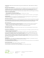
B. Components Included
The On-Q Home WAP includes the following components (see Figure 1):
• WAP Assembly
• WAP Mounting Ring
• WAP Cover
• WAP 48VDC Power Supply with AC cord
• WAP Power Over Ethernet (POE) Inserter Module
• CAT5e Jumper Cable
• WAP Manual on CD
• WAP IS Sheet and User Guide
Figure 1
C. Replacement Parts
Replacement parts available for the On-Q Home WAP include:
• WAP 48 VDC Power Supply with AC cord (P/N 364723-01)
• WAP Power Over Ethernet (POE) Inserter Module (P/N 364719-01)
• WAP Cover (P/N 364724-01)
Innovations in Home Living.
301 Fulling Mill Road, Suite G
©Copyright 2004 by OnQ Technologies, Inc All Rights Reserved.
Middletown, PA 17057
www.onqhome.com
(800)-321-2343
Page 2
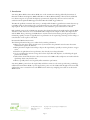
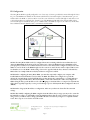
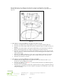
D. Installation Environment
The preferred location for an installed On-Q Home WAP is in the ceiling of the top floor, centrally
located in the home (see Figure 2).
If multiple WAPs are installed. they should be located centrally, in overlapping areas.
The WAP is connected to the On-Q Home POE Inserter Module by a single CAT5e cable.
Figure 2
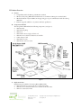
The POE Inserter Module may be located in an On-Q Home Enclosure (see Figure 3), or surface mounted.
It provides both power and an Ethernet data connection for the WAP.
Figure 3
Innovations in Home Living.
301 Fulling Mill Road, Suite G
©Copyright 2004 by OnQ Technologies, Inc All Rights Reserved.
Middletown, PA 17057
www.onqhome.com
(800)-321-2343
Page 3
1.
2.
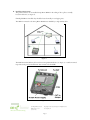
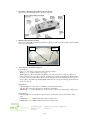
On-Q Home WAP Power Over Ethernet Inserter Module
Figure 4 shows the WAP POE Inserter Module components:
Figure 4
WAP Assembly Installed in Ceiling
Figure 5 shows the WAP Assembly status indicators, which are visible from directly below when the WAP
cover is properly installed:
WiFi
Power
LAN
3.
Figure 5
Status Indicators Detailed Description:
Power Indicator
ON Green The device is powered on and operating normally.
Blinking Green Firmware update is in progress.
Blinking/ON Red The power LED turns RED as soon as the reset button is depressed. If the reset
button is held down for more than 5 seconds, the LED starts to blink during which the WAP’s default
user name, password and IP address will be restored. The LED then turns OFF until the reset button is
released. The power LED keeps blinking RED if the firmware is corrupted indicating that the firmware
needs to be restored.
WiFi Indicator
OFF No Light No mobile station or WAP has associated with this device.
ON Red The wireless interface has been disabled by the firmware.
ON/Blinking Green 802.11b/802.11g connection exists in this wireless domain/active traffic present.
LAN Indicator
OFF No Light No external Ethernet device has been attached and detected. The Ethernet link is
down.
ON/Blinking Amber 10BaseT link detected/active traffic present.
ON/Blinking Green 100BaseT link detected/active traffic present.
Innovations in Home Living.
301 Fulling Mill Road, Suite G
©Copyright 2004 by OnQ Technologies, Inc All Rights Reserved.
Middletown, PA 17057
www.onqhome.com
(800)-321-2343
Page 4
III. Configuration
The On-Q Home WAP is typically configured in one of two ways; (1) From a portable PC connected through the “Data
In” port of the POE Inserter Module in the enclosure which is then connected through its “Data/Power Out” port to a
CAT5e cable to the WAP, or (2) From a PC in one of the rooms of the house, connected through an outlet in the room
to the enclosure where it is patched to the “Data In” port of the POE Inserter Module in the enclosure which is then
connected through its “Data/Power Out” port to a CAT5e cable to the WAP (see Figure 6). In either case, the PC must
have an Ethernet Network Interface Card to communicate with the WAP.
Figure 6
NOTE: The On-Q Home WAP can also be configured from a PC containing a Wireless Network Interface Card
(Motorola WPCI810G wireless PCI card for your desktop PC, or Motorola WN825G wireless PCMCIA card for
your laptop PC), but this is not recommended because it is not secure until you have configured security levels on the
WAP. To connect the PC to the WAP through a wireless connection, ensure the PC.s wireless adapter SSID (Service
Set Identifier) is set to the WAP’s default setting of “motorola” appended with the last 3 characters of the Wireless
MAC address (an example SSID: motorola345) and that no encryption is enabled.
NOTE: Before configuring the On-Q Home WAP, you must first temporarily configure your computer (with
installed Ethernet Network Interface Card) to talk to the WAP. The WAP comes configured to a specific IP
subnetwork (192.168.40.xxx) and its default IP address in that subnetwork is 192.168.40.1, so your PC’s Ethernet
Card must be assigned an IP address, (like 192.168.40.10), on that same subnetwork to talk to and configure the
WAP. Giving the PC a specific IP address is also called assigning it a Static IP address, as compared to a Dynamic IP
address that is typically assigned by a service provider through a process called Dynamic Host Configuration Protocol
(DHCP).
NOTE: Before doing any PC IP Address re-configuration, make sure you first write down all of the current IP
settings.
NOTE: After initially configuring the WAP, using that Static IP Address that you assign, you may need to return the
PC’s IP Address setting to be dynamically assigned by DHCP, if that is what the service provider requires. If you are
using a router, you will also want to change your WAP’s IP address and Gateway settings to be compatible with the
router. These steps are covered at the end of this section.
Innovations in Home Living.
301 Fulling Mill Road, Suite G
©Copyright 2004 by OnQ Technologies, Inc All Rights Reserved.
Middletown, PA 17057
www.onqhome.com
(800)-321-2343
Page 5
A.
Configuring a Windows XP Ethernet Network Interface Card to talk to the WAP
This section includes information on configuring computers with the Windows XP operating system
(differences for 98SE, ME and 2000 will be sited).
NOTE: This configuration assumes you have retained the default interface for Windows XP. If you are
running the .Classic. interface, please note any sited differences for Windows 2000.
1.
Click Start.
2.
Select Control Panel.
(For Windows 98SE, ME and 2000, select Settings first)
3.
Double-click Network and Dial-Up Connections.
(Double Click Network for Windows 98SE and ME and the Network Window is displayed)
4.
Double-click Local Area Connection. The Local Area Connection Status window appears (see Figure 7).
(Step 4 is not applicable for Windows 98SE or ME)
Figure 7
5.
Click the Properties button to go to the Local Area Connection Properties screen.
(Step 5 is not applicable for Windows 98SE or ME)
Innovations in Home Living.
301 Fulling Mill Road, Suite G
©Copyright 2004 by OnQ Technologies, Inc All Rights Reserved.
Middletown, PA 17057
www.onqhome.com
(800)-321-2343
Page 6
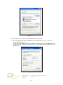
Figure 8
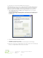
6.
Ensure the box next to Internet Protocol (TCP/IP) is selected (see Figure 8).
7.
Click to highlight Internet Protocol (TCP/IP) and click the Properties button to go to the Internet
Protocol (TCP/IP) Properties screen.
(For Windows 98SE or ME, from the Network Window’s configuration tab, select the TCP/IP line the for
the appropriate Ethernet adapter and Click Properties. From the TCP/IP Properties Window, Click on the
IP Address tab.)
Figure 9
Innovations in Home Living.
301 Fulling Mill Road, Suite G
©Copyright 2004 by OnQ Technologies, Inc All Rights Reserved.
Middletown, PA 17057
www.onqhome.com
(800)-321-2343
Page 7
8.
Click on “Use the following IP Address:” so that the circle is filled (see Figure 9).
9.
Enter 192.168.40.10 into the IP Address field.
10. Enter 255.255.255.0 into the Subnet Mask field.
11. Click OK twice to exit and save your settings.
(For Windows 98SE, ME, or 2000 you will have to restart the computer to save these settings).
12 After the reboot (if appropriate), proceed to the next section to set up the WAP security settings.
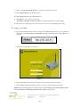
B. Logging on to the WAP
1.
Once the PC’s Ethernet Interface Card is configured on the WAP’s subnetwork, open your web browser
and Enter into the URL field http://192.168.40.1 (the WAP’s default IP address) and press Enter (see
Figure 10).
Figure 10
The login screen will appear (see Figure 11).
Figure 11
2.
Enter the User ID. The default factory setting is ”admin”, without the quotation marks.
3.
Enter the Password. The default factory setting is “motorola”, without the quotation marks.
NOTE: Once you have logged in, for security reasons, you should change the User ID and Password. Be
sure to document the new User ID and Password. For details, see next section.
Innovations in Home Living.
301 Fulling Mill Road, Suite G
©Copyright 2004 by OnQ Technologies, Inc All Rights Reserved.
Middletown, PA 17057
www.onqhome.com
(800)-321-2343
Page 8
4.
Click the Log In button to enter the WAP’s Configuration Utility.
C. Wireless Security Setup
Follow these procedures to setup the correct security protocols for your WAP.
1.
Select Control Panel > Device Security (see Figure 12).
Figure 12
2.
In the Login User ID field, enter in the desired Login User ID. For strong security, select an ID that
contains multiple of case-sensitive characters as well as numbers. It cannot be longer than 64 characters.
3.
In the Login User Password field, enter in the desired Login Password. For strong security, select a
password that contains multiple case-sensitive characters as well as numbers and symbols like ._ + ).. It
cannot be longer than 64 characters.
4.
Re-enter the same Password.
5.
Click Apply.
6.
Once the settings have been accepted, click Restart and log back into the Configuration Utility using your
new User ID and Password.
7.
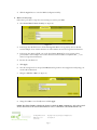
Navigate to Wireless > Basic (see Figure 13).
Figure 13
8.
Change the SSID to a user-friendly name and click Apply .
NOTE: The Channel Number identifies the channel on which the WAP communicates, and each associated
wireless client must use the same channel number in order to communicate (The default channel is 11).
Innovations in Home Living.
301 Fulling Mill Road, Suite G
©Copyright 2004 by OnQ Technologies, Inc All Rights Reserved.
Middletown, PA 17057
www.onqhome.com
(800)-321-2343
Page 9
9.
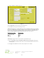
Navigate to Wireless > Security (see Figure 14).
Figure 14
10. Select WPA-PSK from the drop down list of ESS Authentication.
11. Select AES from the drop down list of Encryption Status.
NOTE: The Extended Service Set (ESS) Authentication selection and Encryption Status selection determine
how secure your WAP will be. You may have to match the security settings of your chosen Wireless Network
Interface card to insure operability. The WAP is defaulted to Open System ESS (no authentication) and
None (no security) for Encryption Status. The choices from least secure to most secure are:
Extended Service Set (ESS)
Open System
Pre-Shared Key (PSK)
WPA
WPA-PSK
Encryption Status
None
WEP64
WEP128
TKIP
AES
NOTE: Higher encryption levels are inversely related to data transmission speed.
12. Enter a new Pass Phrase and again in Pass Phrase Confirm. Remember this Pass Phrase so that you can
enter the same phrase for the Motorola client devices on your wireless LAN. Pass Phrase must be between
8 and 63 characters.
13. Click Apply and then Restart. Your wireless security configuration is now complete.
Innovations in Home Living.
301 Fulling Mill Road, Suite G
©Copyright 2004 by OnQ Technologies, Inc All Rights Reserved.
Middletown, PA 17057
www.onqhome.com
(800)-321-2343
Page 10
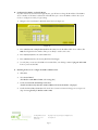
D. Configuring the WAP to work with a Router
If you are connected to the Internet through a Router, you will want to change the IP Address of the WAP to
also be a member of the Router’s subnetwork. This will allow you to access the WAP at a future date, if you
need to re-configure its security or login settings.
1.
Navigate to the Control Panel > Network Access Screen (see Figure 15).
Figure 15
2.
Enter 192.168.1.xxx (example subnetwork for the router) into the IP Address field. Use an address (like
100) that is higher than the number of PCs you are likely to attach to this router.
3.
Enter 255.255.255.0 into the Subnet Mask field.
4.
Enter 192.168.1.254 into the Gateway IP field and click Apply.
5.
To verify that you can access the WAP at its new IP address, run the Ping command (ping 192.168.1.100)
from any router attached PC.
E. Returning the PC used to configure the WAP to DHCP control
1.
Click Start.
2.
Select Control Panel.
(For Windows 98SE, ME and 2000, select Settings first)
3.
Double-click Network and Dial-Up Connections.
(Double Click Network for Windows 98SE and ME and the Network Window is displayed)
4.
Double-click Local Area Connection. The Local Area Connection Status window appears (see Figure 16).
(Step 4 is not applicable for Windows 98SE or ME)
Innovations in Home Living.
301 Fulling Mill Road, Suite G
©Copyright 2004 by OnQ Technologies, Inc All Rights Reserved.
Middletown, PA 17057
www.onqhome.com
(800)-321-2343
Page 11
Figure 16
5.
Click the Properties button to go to the Local Area Connection Properties screen.
(Step 5 is not applicable for Windows 98SE or ME)
Figure 17
Innovations in Home Living.
301 Fulling Mill Road, Suite G
©Copyright 2004 by OnQ Technologies, Inc All Rights Reserved.
Middletown, PA 17057
www.onqhome.com
(800)-321-2343
Page 12
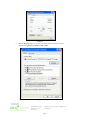
6.
Ensure the box next to Internet Protocol (TCP/IP) is selected (see Figure 17).
NOTE: Although this series of steps is used to re-configure the PC from direct WAP configuration back to
its previous use as a DHCP controlled PC on the Router network, they can also be used to configure the
WAP Network Interface Card for DHCP control by selecting the WAP NIC at the top of this screen.
7.
Click to highlight Internet Protocol (TCP/IP) and click the Properties button to go to the Internet
Protocol (TCP/IP) Properties screen.
(For Windows 98SE or ME, from the Network Window’s configuration tab, select the TCP/IP line the for
the appropriate Ethernet adapter and Click Properties. From the TCP/IP Properties Window, Click on
the IP Address tab.)
Figure 18
8.
Select Obtain an IP address automatically (see Figure 18).
9.
Click OK twice to exit and save your settings.
(For Windows 98SE, ME, or 2000 you will have to restart the computer to save these settings).
10. After the reboot (if appropriate), your PC should be now be ready for operation as before, directly through
the Router, or through the WAP (if a Wireless NIC card was installed).
Innovations in Home Living.
301 Fulling Mill Road, Suite G
©Copyright 2004 by OnQ Technologies, Inc All Rights Reserved.
Middletown, PA 17057
www.onqhome.com
(800)-321-2343
Page 13
IV. Firmware Updates
As with most complex products, at some time in the future you may be required to update your firmware. To find
out what firmware level you are currently running, use your browser to access the IP address of the WAP, and after
inserting your User ID and Password, click on the Log In button (see Figure 19).
Figure 19
A. Checking / Updating Firmware Level.
1.
Navigate to the Control Panel > Firmware Update screen (see Figure 20).
Figure 20
This screen (see Figure 20) enables you to verify/update the firmware (WAP’s hardware control
mechanism). Listed on this screen is the current version of the Model Number, Serial Number, and
Firmware Number; enabling you to verify that you are running the most current version.
2.
If you need to update the firmware, you must first get the latest firmware from this website
www.motorola.com/broadband/networking.
3.
Download the latest file to your computer.
4.
To locate the file you downloaded, type the path to the file or click Browse and navigate to it.
5.
Click UPDATE to update the WAP with the selected firmware file. The WAP will inform you that you
successfully updated the unit.
6.
Follow the prompts for restarting.
Innovations in Home Living.
301 Fulling Mill Road, Suite G
©Copyright 2004 by OnQ Technologies, Inc All Rights Reserved.
Middletown, PA 17057
www.onqhome.com
(800)-321-2343
Page 14
V. Troubleshooting
This section will detail possible solutions to common problems that might occur in using the On-Q Wireless Access
Point (WAP).
A.
Contact Information
If you are unable to locate a solution here, please access our website at www.onqhome.com for the latest
information. You can also reach us at 1-800-321-2343.
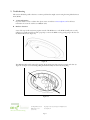
B. Hardware Situations
Some of the steps in this section may require removal of the WAP cover, or the WAP Assembly unit to verify
cabling. Use a small pointed object, like a paper clip to remove the WAP cover by gently prying in the slot near
the Power indicator (see Figure 21).
Figure 21
The WAP Assembly itself is removed by pressing the mounting ring clasp extensions toward each other (see
Figure 22 and Figure 23) and carefully pulling the WAP Assembly out of the Mounting Ring.
Figure 22
Innovations in Home Living.
301 Fulling Mill Road, Suite G
©Copyright 2004 by OnQ Technologies, Inc All Rights Reserved.
Middletown, PA 17057
www.onqhome.com
(800)-321-2343
Page 15
Figure 23
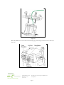
When the WAP has been removed from the mounting ring, the following connections can be verified (see
Figure 24):
Figure 24
Innovations in Home Living.
301 Fulling Mill Road, Suite G
©Copyright 2004 by OnQ Technologies, Inc All Rights Reserved.
Middletown, PA 17057
www.onqhome.com
(800)-321-2343
Page 16
Power Receptacle – Five volt DC power is extracted from the POE Extractor Module in the WAP Assembly
(the 5VDC is derived from the 48VDC fed to the WAP Assembly over the single CAT5e from the POE
Inserter Module in the Enclosure).
LAN Port – Ethernet data is extracted from the POE Extractor Module in the WAP Assembly. The LAN port
supports either 10BASE-T or 100BASE-T transmission speeds as well as straight-through and crossover
Ethernet cables (the Ethernet data is derived from the single CAT5e fed to the WAP Assembly from the POE
Inserter Module in the Enclosure).
Reset Button - A dual-function button. A brief button press resets the WAP unit, while a longer button press
resets the WAP unit to the default login settings. If the WAP is experiencing trouble connecting to the Internet,
briefly press and release the Reset button to reset the WAP. The WAP will retain its configuration information
during this reset operation. To reset the unit to the factory defaults, while the unit is powered, press and hold
the Reset button for more than 10 seconds. This clears the WAP’s user settings, including User ID, Password,
IP Address, and Subnet Mask.
NOTE: Refer to the Section III Configuration for re-configuring the WAP.
Antenna Connection – Cable connects to the On-Q WAP antenna used for wireless connections.
NOTE: When initially removed from the box, a stub antenna will be connected to this connector. For better
coverage, it should be removed and replaced by the On-Q WAP antenna cable.
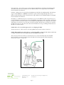
After connections have been verified, or the unit has been reset, insure the CAT5e cable from the POE
Inserter Module is connected, and push the unit through the mounting ring until the Mounting Ring
Clasps snap into place (see Figure 25).
Figure 25
Innovations in Home Living.
301 Fulling Mill Road, Suite G
©Copyright 2004 by OnQ Technologies, Inc All Rights Reserved.
Middletown, PA 17057
www.onqhome.com
(800)-321-2343
Page 17
Then install the center cover, making sure the tabs in the cover line up with the holes on the WAP
Assembly. This will insure that the light pipes from the status lights on the WAP are properly aligned (see
Figure 26).
Figure 26
1.
My computer is experiencing difficulty connecting to the wireless network.
a. Ensure that your Wireless Access Point (WAP) is powered on and that the Wireless LED is lit.
b. Ensure that your wireless adapter (PCI card, Notebook or Ethernet adapter) is installed correctly and
is active.
c. Ensure that your wireless adapter’s radio signal is enabled and set to the same channel on which the
WAP is communicating. Review your adapter’s documentation for further instructions.
d. Ensure that your wireless adapter for your PC and the WAP have the same security settings that will
allow your computer to access the wireless network. See Section III Configuration for details on how to
adjust security settings.
e. Ensure that your WAP is within range of your router or is not behind an obstruction, for example
metal structures will interfere with the signal, as will 2.4 GHz cordless phones, and microwaves.
f. Ensure that your antenna is connected.
2.
My computer is experiencing difficulty in connecting to the WAP.
a. Check that all of your cable connections are tight and secured. This includes the cables to your
modem, the router, the WAP and to your PC.
b. Ensure that your LEDs are not lit Red or not at all. For further information about LED descriptions,
see Section II: Product Overview.
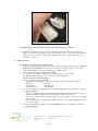
c. Ensure that you are using Ethernet cables and not telephone cables (see Figure 27). Ethernet cables use
a wider RJ-45 style plug using 8 wires where telephone style plugs use the smaller RJ-11 (4 pin) or RJ25 (6 pin) style plugs.
Innovations in Home Living.
301 Fulling Mill Road, Suite G
©Copyright 2004 by OnQ Technologies, Inc All Rights Reserved.
Middletown, PA 17057
www.onqhome.com
(800)-321-2343
Page 18
Figure 27
NOTE: The plug on the left is RJ-45; the plug on the right is RJ-11. Use only RJ-45.
d.
Ensure that your Ethernet adapter is enabled. Check the System Tray at the bottom right of your
display to see an icon that looks like a monitor. You can click on this to see the status of your Ethernet
adaptor. Also in Control Panel > Network and Dial-Up Connections, you can examine the state of
your Ethernet adaptor.
C. Software Situations
1.
I would like to see if my Internet connection is alive.
a. For this, you will use the ping command to test the connection. Before attempting, ensure that Obtain
an IP address automatically has been selected in the computer’s settings and that you have an IP
address assigned. Refer to Section III: Configuration , for further details.
b. Open a command prompt by clicking Start and Run.
(For Windows 98 and ME, in the Open field, type command and press Enter or OK.)
(For Windows 2000 and XP, type cmd or, navigate using your Start button to
Programs>Accessories>Command Prompt.)
c. In the Command window, type ipconfig.
You should see an IP address for your network adapter similar to the following example:
IP Address. . . . . . . . . . . . : 192.168.40.3
Subnet Mask . . . . . . . . . . . : 255.255.255.0
Default Gateway . . . . . . . . . : 192.168.40.1
d. In the Command window, type ping followed by the WAP’s IP address and press Enter. For example
type: ping 192.168.40.3.
There is a good possibility that the Default Gateway’s IP address is the WAP’s IP address. You
can verify the WAP’s IP address on the Control Panel > Network Access screen.
If you receive a reply (the first word will be Reply.), then your computer is connected to the WAP.
Proceed to Step e.
If you do NOT receive a reply, try from a different computer to verify that the first PC is not the
cause of the problem.
e. In the Command window, type ping and your ISP’s default gateway and press Enter. For example
type: ping 192.168.40.1.
Innovations in Home Living.
301 Fulling Mill Road, Suite G
©Copyright 2004 by OnQ Technologies, Inc All Rights Reserved.
Middletown, PA 17057
www.onqhome.com
(800)-321-2343
Page 19
f.
2.
If you receive a reply (It might look something like this: Reply from 216.109.125.72.), then your
connection to the Internet is alive and well. You can verify the ISP’s IP address at the Gateway IP
field on the Control Panel > Network Access screen.
If you do NOT receive a reply, try from a different computer to verify that the first PC is not the
cause of the problem.
If you cannot determine your ISP’s default gateway, ping www.yahoo.com or another known web
location.
I cannot access the Web-Based Configuration Utility for the WAP.
a. Verify your Ethernet connection to the WAP.
b. Verify that the IP address of the PC being used to configure the WAP is on the same network as the
WAP’s configuration IP address.
c. The IP address of your network adapter must be on the same network and not a duplicate of any
others on the network (for example: 192.168.40.3 and using a subnet mask of 255.255.255.0 can be
used to login to the WAP’s default IP address of 192.168.40.1). Refer to Section III: Configuration
on how to adjust the IP address for your PC.
d. Verify that you can ping the WAP on this IP address. In the Command window, type ping and your
WAP’s default IP address and press Enter. For example type: ping 192.168.40.3.
e. If you have changed the factory configured default IP address of the WAP, you will need to set your
network adapter accordingly.
f. Verify you are entering the correct URL in the browser. The default is http://192.168.40.1.
g. If you think you have changed the IP address used to configure the WAP and cannot remember it,
you must reset the unit back to factory defaults. To do this, press and hold the reset button for more
the 5 seconds. This clears the WAP’s user settings, including User ID, Password, IP Address, and
Subnet mask.
h. Once the WAP is reset to factory default, re-verify the Ethernet connectivity and IP address issues.
i. Verify you are using the latest version of IE or Netscape. IE 5.2 and below are not supported.
Innovations in Home Living.
301 Fulling Mill Road, Suite G
©Copyright 2004 by OnQ Technologies, Inc All Rights Reserved.
Middletown, PA 17057
www.onqhome.com
(800)-321-2343
Page 20