1
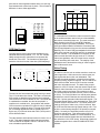
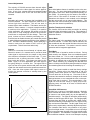
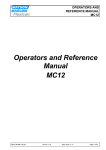
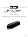
PULNiX America, Inc.
Industrial Products Division
Introduction to
"Video 101"
September 1992
By K. MacDonald
Table Of Contents
Introduction 1
CCD 1
Types of CCD Arrays 1
CCD Size Format 2
Video Format 2
Video Timing 2
Interlace & Non-interlace Video 3
Camera Features 3
Lens Mounts
Tripod Adapter
Camera Back End
Internal Features 4
Shuttering
Integration
Async Reset
Internal Adjustments 5
AGC
Gamma
AWB
Frame Mode
Field Mode
Intensified CCD Cameras 5
Lenses 6
Introduction
Charge Coupled Device
This guide titled Video 101 was prepared by the request
of a handful of Sale Representatives for PULNiX America.
The request was brought to our attention at the 1992
National Sales Meeting in San Francisco, California.
Pixel
Vertical Shift Register
This guide is intended for "New Comer's" to the video
world. Also to the new Rep's and Distributors who come
aboard with no prior knowledge of PULNiX video products.
This guide is designed to be "low tech." This does not
mean that a seasoned video GURU cannot used this
primer from time to time to refresh those memory banks.
Hopefully, this guide will open the doors for all you newcomers to explore the exciting world of Video and Image
processing. If ever the time arises for the need to ask a
question regarding PULNiX products, please call our technical staff during normal business hours (8-5 Pacific time).
AND REMEMBER, THERE IS NO SUCH THING AS A
STUPID QUESTION WHEN TALKING TO OUR TECH
STAFF!
Array
TYPES OF CCD ARRAYS
PULNiX currently uses two types of CCD arrays in the
main product line up. They are the Frame Transfer and
Interline Transfer CCD types. The main difference
between the two types of arrays is the way the devices
shift out the current charge of pixels. The Interline
Transfer CCD first transfers the current element (pixel)
charges into vertical shift registers. Once the vertical shift
has taken place, the horizontal registers begin shifting out
into a horizontal shift register. This is where each horizontal line of video begins its journey through the camera's electronics to make it a RS-170 standard video signal.
By the way, RS-170 is the standard that makes the video
signal acceptable so that it will interface to various video
equipment such as a video monitor.
CCD (CHARGE COUPLED DEVICE)
The best place to start is probably the front end of the
video camera. The term CCD stands for Charge Coupled
Device. The CCD is a large scale integrated (LSI)
device. We will just call it an imager for short. In a nutshell this device has the ability to detect light charges
(photons) and convert this light into electrical charges.
The structure of the sensitive area (array) of the CCD is
that the light sensitive diodes (pixels) are positioned very
accurately in horizontal and vertical rows to make up what
we call a matrix array. The CCD array also contains shift
registers in the horizontal and vertical position. These
shift registers will shift out all of the charge levels for
every single pixel on the array. This process is not an
easy task. If you think about it, the current pixel element
size is 768 horizontal by 493 vertical for a CCD array
which equals 378,624 pixels. That's a lot of shifting.
Interline Transfer CCD Imager
Pixel
Vertical Shift Register
Camera Front End
CCD
CCD
Glass Cover
Horizontal Shift Register
The second type of CCD is the Frame Transfer type. This
type of CCD transfers vertically within its own axis. This
means that the pixel area acts like a shift register itself.
You should notice that the frame transfer CCD has a storage area where the electrical charge is temporarily stored
until it can be shifted out through the horizontal register.
Also, it should be noted that the position of the actual
1
pixel area is closer together because there is no shift register between each vertical row of pixels. This will make a
difference in some video applications.
CCD Aspect Ratio
Horizontal
4 Part
V
e
r
t 3 Part
i
c
a
l
Frame Transfer CCD Imager
Pixel
CCD
CCD
Video Format
Storage Area
To understand the format that a video camera will output
to the outside world we need to look at a few standards
that various committee's have set. The most common in
North America is the RS-170 and NTSC (National
Television System Committee) standards. For Europe,
CCIR (International Radio Consultative Committee) and
PAL (Phase Alternation Line) are the common standards.
Basically, RS-170 and CCIR are standards for black and
white video cameras, and NTSC and PAL are standards
for color cameras. The standards are necessary in that
video cameras and other devices such as TV monitors,
video frame grabbers, and VCR's must have a common
way of interacting with each other. The majority of the
standards have to deal with the timing of various signals.
We will discuss this next.
Horizontal Shift Register
CCD Size Format
Currently there are three format sizes available for the
industrial and security markets; 1/3", 1/2", 2/3" formats.
Oddly enough the size format does not represent the
actual size of the CCD. The formats were developed
under the old rules from the video tube (VIDICON) days.
CCD Size Format
1/3 Inch Format
6
3.6
1/2 Inch Format
8
4.8
Video Timing
2/3 Inch Format
11
In order for a device such as a video monitor to receive a
video signal from a video camera, the camera must provide signals that the monitor can understand. This
includes the signal amplitude ( voltage level) as well as
frequency timing ( signal occurrence). RS-170 and NTSC
have similar formats, but the NTSC must also contend
with color information as well. The basic timing requirements for a RS-170 format is that the camera outputs two
fields of video information every 1/30 of a second. It takes
two fields to make up a frame (full resolution) of video.
The camera outputs one field at a time (1/60 of a second
or 60 Hz). For every field there is a vertical pulse generated inside the camera. Between two vertical pulses there
are 262 .5 pulses generated called horizontal signals. The
horizontal signals specify a new horizontal line. Each field
consists of 262.5 horizontal lines. Two fields (frame) will
make up 525 lines of video every 1/30 of a second. Now
for CCIR and PAL these timing signals change a bit. First
of all the vertical timing changes to 50 pulses per second
(50Hz). Secondly, the horizontal pulses occurs 312.5
times per vertical pulse. This makes up the 625 lines
(frame of resolution) available on a CCIR standard. The
vertical and horizontal signals that were described here
are called the H & V SYNC timing. When both signals are
combined together this is called a COMPOSITE SYNC
SIGNAL.
6.6
4.8
6.4
8.8
Dimension In Millimeters
The trend in size format has been going from big to small.
The 1/3" is the latest size format. The idea is to make the
CCD smaller so that the overall camera size is reduced.
Take a look at our TM-7X camera for size. At PULNiX this
is considered our smallest, but don't be surprised if a
smaller one is unveiled soon. One problem with smaller
CCD's is that the equivalent FOV (field of view) is reduced
thus requiring a change in optics. This can cause a problem for existing applications that are already spec'd. in.
By the way, if you do not know what FOV is, don't panic it
will be discussed later.
The ratio between horizontal and vertical is close to 4 to 3
or 4/3. This again follows the video tube type cameras.
This is known as the ASPECT RATIO. This ratio is common to broadcast specifications.
2
Camera Features
RS-170 Composite Video
At this point we will get into more of the specific functions
that are applicable to PULNiX's video line.
Vertical Pulse
Field No. 1 (Odd Field)
16.7 ms (59.94Hz)
Field No. 2 (Even Field)
16.7 ms (59.94Hz)
262.5 H
262.5 H
Lens Mount
Again the best place to start is at the front end. The front
of the camera is where the lens will be attached. The two
most common type of mounts are the bayonet and the Cmount. A majority of the cameras come with a C-mount
type thread on the front end. Some of the older models
like the TM-34K and TM-540 have bayonet mounts. The
newer models can use bayonet type lenses with a special
adapter part# BC-5 (note this adapter functions as a
close-up ring). Also the bayonet models can be easily
adapted to use C-mount type lenses as well. For your
information, lenses will be discussed further down the
road.
63.5µs
(15.75KHz)
Horizontal Pulse (H)
1 Frame
33 ms (30Hz)
525 H
Basically, the SYNC provides a signal to synchronize the
video with other video equipment. Sometimes the video
equipment that is used with PULNiX cameras require the
necessary SYNC signals to drive a camera. In this situation, the camera must have the ability to accept an external sync source. Note: Not all of PULNiX cameras
accept an external sync source. So make sure to read
the data sheet and look for sync specifications to determine if the camera has that capability.
Tripod Adapter
PULNiX's full line of video cameras have the feature of a
tripod mount adapter. This will allow a user to physically
mount the camera to a fixture such as a camera tripod
stand. The video standard is a 1/4" coarse thread for the
U.S. market. Some cameras also have a M6 metric
thread available. To determine what type of thread
dimensions are available for a particular camera look at
the camera data sheet under dimensions.
Interlace and Non-Interlace Video
Interlace and non-interlace video is the way the actual
horizontal lines of video information will be scanned out,
for example, to a video monitor. The standard operation
is the interlace mode. In the interlace mode, the first field
is scanned out on the monitor which is the odd field (odd
horizontal video lines). Once the odd field is completed
the even field (even horizontal video lines) is started back
at the top (known as retrace) and scanned down until it
reaches the bottom. Remember, each field is timed 16.7
msec. apart. The interlacing mode of operation is the
most common way of displaying video on a monitor.
TM-7EX Tripod Adapter
2x M6, 6mm DP
Non-interlace Scanning
Even Field
Odd Feild
Horizontal Line
1/4 - 20UNC - 2B
1
2
3
4
5
6
7
8
9
.
.
.
.
.
.
.
.
.
.
Camera Back End
The back end of the camera is where most of the action
takes place. This is where the camera's power, video,
sync, auto iris controls, and shutter control are located.
The majority of our camera line has the following configuration in terms of the type of connector.
518
519
520
521
522
523
524
525
TM-745E Back End
12 Pin Connector
6 Pin Connector
For non-interlace mode, the camera will only scan out the
same field over and over again. On most of PULNiX's
cameras, this will require the camera to be operated with
an external sync input only.
VIDEO
OUT
LENS
3
PWR IN
EXT SYNC
BNC Connector
The 12-pin connector provides connections for power
(+12V DC) and composite video. If the camera model is a
RGB camera such as the TMC-74 it will provide a separate line for each video color (RGB). The 12-pin connector is also where the external sync input is located.
faster the shutter speed.
Many machine vision applications require shuttering
because typically during an inspection process the object
is moving. When shuttering at higher speeds, higher
intensity lighting may be required. Remember that high
shutter speeds translate into shorter exposure times
which means less light that the pixels are exposed to.
One drawback to shuttering a CCD video camera is that
the resolution is cut down to one field. To solve this problem, the best thing would be to use strobe lighting instead
of shuttering. In this way, a full frame of resolution is
achieved.
The BNC connector is used for composite video output.
The 6 pin connector is for auto iris or shutter control. This
six pin connector is used to connect to a thumb wheel
switch to set variable shutter speeds (variable shutter is
on the newer lines of video cameras). If an auto iris lens
is required, then this six pin connector is used to control
the auto iris lens.
Integration
Long term integration is the opposite of shuttering.
Integration refers to the time that the pixels are accumulating a charge (light). Long term integration is defined as
an exposure time longer than one field. Applications that
involve long term integration usually are in a very dark
environment. To compensate for this situation, we
expose the pixels longer than one field to capture as
much of light as possible. The limiting factor in this type
of application is usually the noise (thermal) that is accompanied with long term integration. The longer the integration time the more noise present. To help this noise problem we have made peltier cooling available to help keep
the thermal noise down by cooling the imager. The cameras that have this feature require an external signal to
control the integration. Also, to capture the exposed
image, it is necessary to use a field or frame grabber to
store (freeze) the image. PULNiX has a field grabber
(VF-400X) for this purpose.
One final note on connectors. Always consult a data
sheet for connector pinout information because there may
be a subtle difference in the way the connector is wired
from model to model.
A typical way to operate a PULNiX video camera would
be to use a PD12P desk-top power supply and connecting
it to the 12-pin connector on the camera, and take the
video out from the BNC connector to a monitor. Another
common method is to use our standard 12P-02 cable (12pin female connector on one end and 12 flying leads on
the opposite end) and connect it to the camera on one
end and wire the opposite end to a power supply (yellow
wire +12V DC and the grey wire 0V DC). The video output is now available both on the flying leads (video red
coax and ground is red shield) or by using the BNC connection. This method also allows for connections for
external sync input and other special signals through the
flying lead end of the cable.
Asynchronous Reset
The asynchronous reset capability allows the camera to
reset the internal vertical drive (sync) to start a scan
again. This feature is used when an application requires
a camera to scan at a specific time. Machine vision usually requires a camera to capture an image of an object
on the fly at a specific time and place to guarantee that
the image will be in the center of the FOV (field of view).
A scenario would be that a box is flying down a conveyor
and a camera is suppose to capture a bar code image off
the side of a box to verify the quality of the bar code. Now
the box is positioned next to the camera and a sensor is
triggered to signal the camera to start a new scan so that
the bar code is in the total FOV. This will allow the image
processing side (computer) of the application to capture
the image and perform the necessary task of making a
decision (Go/ No/Go) to accept or reject this bar code
image based on what the camera has seen. Think what
would happen if the camera was free running when the
box was in the FOV. Probably what would happen is the
camera would scan and only capture a portion of the bar
code, thus the image processor would reject that box.
Note that in an application like this, shuttering would be
used in conjunction with the asynchronous reset. One of
our newest cameras, the TM-720, is a perfect fit for this
application. It has both the shuttering and async features.
Internal Features
Most of PULNiX's camera series provide certain functions
that enhance the functionality of a camera to meet a wide
range of applications. Some of the common features are
as follows:
Shuttering
For you camera buffs, this may be nothing new to you, but
for the newcomer here is the story behind shuttering.
Typically when an object is moving at a fast pace and you
take a picture of that object, you will notice that the image
is somewhat blurred. The reason for this is that when the
snapshot was taken, the shutter inside the camera opens
to capture an image over a period of time (known as
exposure time). During this time the object is moving
across the image plane of the camera and the end result
is a blurred image. To compensate for this problem we
need to shorten the time the shutter stays open. This will
allow the object to be exposed to the camera's image
plane for a short time period, thus freezing the object and
eliminating the blur. On a 35mm, camera shuttering is
done by mechanical means, but on CCD video cameras
it's done by electrical means.
On our newer line of CCD cameras, shuttering is done by
reducing the amount of time that each pixel captures
exposed light during each field. The shorter the time the
4
Internal Adjustments
The majority of PULNiX cameras have internal adjustments to enhance the video signal for various applications. A few of our cameras have some external control
switches available such as the TM-7CN and TM-7EX
cameras.
AWB
Auto white balance feature is available on the color cameras only. The auto white balance adjusts the white or
the reference color level. White comprises all primary colors (RGB). By powering up the camera, the AWB is
reset. Also a reset switch is located on the camera.
Sometimes this feature is not needed; can be disabled
and the camera will run on manual white balance. This
will relieve the user from having to reset the white balance
every time the camera is powered up.
AGC
Automatic gain control is a feature that is available on all
PULNiX cameras. The AGC adjusts the video level to
various light level conditions. This will not work in
extreme light or dark conditions. This feature can be disabled for various reasons. A common example would be
a machine vision application. Typically in a machine
vision application, the processor part would not like the
video level to keep changing because the processor
would have to compensate for this change. This is not
good, it takes too much valuable processing time. It
would be best to disable the auto gain control and provide
a stable lighting environment around the vision inspection
area. The AGC is disabled internally. When specifying a
camera, make sure the mode of AGC is set to your
requirements. This will save time and money!
Interline Transfer mode selection
The Interline CCD has the ability to transfer its existing
horizontal video information in two ways. This selection of
mode of operation is selectable by an internal jumper
inside the camera.
Frame Mode
The frame mode is the standard interlace mode of horizontal line transfer. For each field, with the odd lines are
first transferred, then the second field when the even lines
of video are transferred. This mode is used for normal
operation and for integration applications.
Gamma
Gamma is a correction for non-linearity of a picture tube.
What this means is if a camera was to provide a linear
video signal to a picture tube, the output on the picture
tube would not correspond to the linear input. To compensate for this, a gamma correction is made. This is
done inside the camera. This feature can also be disabled. Again, in a vision application, the video signal is
not going directly to a monitor first. The signal will be
input into the vision system which would prefer the linear
signal from the camera and not the gamma-corrected version. Once the vision system video signal is sent to a
monitor the gamma correction is already done by the
vision system.
Field Mode
The field mode of operation works as follows: During
each transfer, two adjacent lines are combined together
and then shifted out. This is used in applications that
involve shuttering, because during shuttering the cameras
sensitivity is reduced due to the reduction of integration
time. When shuttering, by combining the odd and even
lines it will help in the sensitivity being that the line charge
is summed together thus increasing the sensitivity by 2.
Note: From camera model to model the factory settings
may differ. Please refer to the data sheet or call your
Factory Inside Sales person for correct factory specs.
This will save time in the long run. From time to time a
customer has returned a camera for changes in the mode
settings because no one consulted the user on the operating mode that is required. This communication oversight can cost the user money in repair service fees,
shipping costs, and most of all trust in PULNiX and in
PULNiX Resellers.
Gamma Correction
Picture Tube Output
Gamma Correction From Camera
gamma= 1/2.2 = 0.4545
Desired linear output
Effect of picture tube (non-linear)
(a = 2.2)
Camera Face Plate Illumination
5
Intensified CCD Cameras
PULNiX has a variety of intensified cameras. Basically
these cameras are used in very dark conditions. The type
of camera to use would greatly rely on the application it
would be used for. Two types of intensifier camera designation are the DN type and NV type. The DN (day/night)
cameras have the ability to operate with a MND (motorized neutral density) or equivalent lens in a night to sunny
day environment unattended. The NV (night vision) cameras must be supervised to manually adjust the exposure.
The intensifier tube itself is very sensitive to long exposure from bright scenes. It is possible to burn in an image
and cause permanent damage to the photo sensitive part
of the intensifier. The intensifier is coupled to the camera
in two different methods. One is to use fiberoptic coupling
in which the fiber is attached from the intensifier directly to
the CCD. The second method is the lens relay which
uses lenses to converge the scene from the intensifier to
the CCD. Both methods have benefits specific to a type
of application. In general, the fiberoptic type has better
light transmission and resolution. The lens coupled type
costs less and holds up better in rugged environments.
H&V FOV
H = Horizontal Height
Top View
θ H = view angle
A few of the intensifiers have gating capabilities. This feature allows the tube to be turned on and off at a very rapid
rate (up to 5 nanoseconds). Gating allows for short exposure time to capture events that occur at a very fast rate
such as a pulsed laser beam modulated at a high frequency or an explosion.
FL
θ V= view angle
Lens
V = Vertical Height
tion of 1 (M=1). A 1" format camera with a 25mm focal
length lens (≈1") also has M=1. A 2/3" format camera
with a 16mm lens has M=1 and a 1/2" using a 12.5mm
lens gives M=1. This explains why a change in CCD format size without changing the lens will change the field of
view. This is something that is frequently over looked
when changing camera format sizes in an existing application. F/Stop (F/Number , F/#) refers to the speed in
which a lens can pass light. A typical lens would be a
25mm with f/1.4. This translate into a 25 millimeter focal
length with an F-Stop of 1.4. The F/Number can be calculated by dividing the focal length of the lens by its diameter. As the F/Number gets larger, the light speed
decreases and this usually means a lower contrast level
or image quality. Typically, the faster lenses have larger
diameter optics that will pass more light and usually will
cost more than the slower speed lenses. Lighting conditions should always be considered when selecting lens
speeds.
PULNiX America has over 100 different lenses available
to use with the full line of video cameras. The type of lens
that is needed for a particular application depends on various factors that we will get into right now.
The function of a lens is to collect reflected light from a
scene and form a focused image of the scene on a camera's sensor plane.
H
V
V
CCD
Lenses
FO
L
Side View
Intensifier cameras as a whole have many application
possibilities in low light surveillance, microscopic applications, and in astronomy.
Field of View
H
V
The following formulas can be used to determine the focal
L
Format
To start off, we must determine the total area the camera
must see. This is called the Field of View (FOV).
The scene that comprises the FOV has horizontal width
(H) and vertical height (V) dimensions. Based on the distance (L) and the total FOV, we can select a lens to meet
a particular application.
1"
2/3"
1/2"
H
12.8 x L
f
8.8 x L
f
6.4 x L
f
V
9.6 x L
f
6.6 x L
f
4.8 x L
f
length which will determine the relative size of the object
viewed.
Lenses are described in terms of their focal length (millimeters). The focal length (FL) is defined as the distance
from the center of lens to the CCD array surface. The
focal length will determine the view angle through the lens
which will determine the FOV based on distance to the
scene. Magnification (M) is a number expressing change
in object-to-image size. The human eye has a magnifica-
f= Focal length of the lens (mm)
H= Horizontal dimensions of object (mm)
V= Vertical dimensions of object (mm)
L= Distance from the lens to the object (mm)
For further information concerning lens applications,
please refer to PULNiX Lens Guide.
6