1
Brady
Bradyprinter Models 2461 and 3481
Operator’s Manual
(TEMP COVER)
(DO NOT PRINT)
(DO NOT PRINT)
Copyright Information:
CG Triumvirate is a trademark of Agfa Corporation.
CG Times based upon Times New Roman under license from The Monotype
Corporation.
Firmware (Software) Agreement
The enclosed Firmware (Software) resident in the Printer is owned by Licensor or its
suppliers and is licensed for used only on a single printer in the user’s Trade or Business.
The User agrees not to, and not to authorize or permit any other person or party to
duplicate, or copy the Firmware or the information contained in the non-volatile or
programmable memory. The firmware (Software) is protected by applicable copyright
laws and Licensor retains all rights not expressly granted. In no event will Licensor or its
suppliers be liable for any damages or loss, including direct, incidental, economic,
special, or consequential damages, arising out of the use or inability to use the Firmware
(Software).
Information in this document is subject to change without notice and does not represent a
commitment on the part of Brady Worldwide, Inc. No part of this manual may be
reproduced or transmitted in any form or by any means, for any purpose other than the
purchaser's personal use, without the expressed written permission Brady Worldwide Inc.
All rights reserved. Printed in the United States of America.
© Copyright 2000 by Brady Worldwide, Inc.
Part Number: 88-2241-21
Revision: B
Agency Compliance and Approvals:
UL1950 Information Technology Equipment
C22.2 No. 950-M93
C
US
Listed
EN60950
For 230 Volt Operation (Europe): Use a cord set, marked "HAR," consisting
of a min H05VV-F cord which has a minimum 0.75 square mm diameter
conductors, provided with an IEC 320 receptacle and a male plug for the
country of installation rated 6A, 250V
Für 230 Volt (Europa): Benützen Sie ein Kabel, das mit "HAR" markiert ist,
bestehend mindestens aus einem H05VV-F Kabel, das mindestens 0,75
Quadratmillimeter Drahtdurchmesser hat; sowie eine IEC320 Steckdose und
einen für das Land geeigneten Stecker, 6A, 250 Volt.
As an Energy Star Partner, the manufacturer has determined that this product
meets the Energy Star guidelines for energy efficiency.
The manufacturer declares under sole responsibility that this product conforms
to the following standards or other normative documents:
EMC:
EN 55022 (1993) Class B
EN 50024 (1998)
EN 45501 (1992)
Safety: This product complies with the requirements of EN 60950/All:1997
Gost-R
FCC: This device complies with FCC CFR 47 Part 15 Class A.
; Note: This equipment has been tested and found to comply with the limits for
a Class A digital device, pursuant to Part 15 of the FCC Rules. These
limits are designed to provide reasonable protection against harmful
interference when the equipment is operated in a commercial
environment. This equipment generates, uses, and can radiate radio
frequency energy, and if not installed and used in accordance with the
instructions in this manual, it may cause harmful interference to radio
communications. Operation of this equipment in a residential area is
likely to cause harmful interference in which case the user will be
required to correct the interference at his own expense.
Important Safety Instructions:
This printer has been carefully designed to give you many years of safe, reliable
performance. As with all electrical equipment, there are some basic precautions
you should take to avoid hurting yourself or damaging the printer:
¾
Before using the printer, carefully read all the installation and operating
instructions.
¾
Observe all warning instruction labels on the printer.
¾
Install the printer on a flat, firm, solid surface.
¾
To protect your printer from overheating, make sure all openings on the
printer are not blocked.
¾
Do not place the printer on or near a heat source.
¾
Do not use your printer near water, or spill liquid into it.
¾
¾
Ensure that your power source matches the rating listed of your printer. If
unsure, check with your dealer or local Utility provider.
Do not place the power cord where it will be stepped on. If the power cord
becomes damaged or frayed, replace it immediately.
¾
Do not insert anything into the ventilation slots and openings on the printer.
¾
Use a qualified, trained service technician should the printer ever need repair.
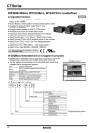
Printer Overview
1.0 Introduction........................................................................ 1
1.1 About this Printer............................................................... 2
1.1.1 Standard Features .................................................... 2
1.1.2 Optional Features .................................................... 3
1.2 Option Installation ............................................................. 5
Getting Started
2.0 Before using the Printer ..................................................... 7
2.1 Choosing Media and Ribbon ............................................. 9
2.1.1 Controlling Print Quality......................................... 9
Printer Setup
3.0 Introduction...................................................................... 11
3.1 Connecting the Printer ..................................................... 11
3.1.1 Interfacing ............................................................. 12
3.2 Loading Media................................................................. 14
3.2.1 Roll Media............................................................. 16
3.2.2 Fan-Fold Media ..................................................... 17
3.3 Loading the Media Rewinder .......................................... 18
3.3.1 Winding Labels ..................................................... 18
3.3.2 Winding with the Peel and Present Option ........... 20
3.4 Loading Ribbon ............................................................... 22
Using the Front Panel
4.0 Front Panel Operation...................................................... 25
4.0.1 Ready Mode .......................................................... 25
4.0.2 Menu Mode ........................................................... 26
4.0.3 Quick Test Mode................................................... 27
4.0.4 Indicators............................................................... 28
4.0.5 LCD (Display)....................................................... 28
4.0.6 Factory Default Resetting...................................... 29
i
4.1 The Menu System ............................................................ 30
4.1.1 Media Settings....................................................... 31
4.1.2 Print Control.......................................................... 32
4.1.3 Printer Options ...................................................... 33
4.1.4 System Settings ..................................................... 34
4.1.5 Communications ................................................... 38
4.1.6 Diagnostics ............................................................ 40
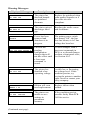
4.2 Display Messages ............................................................ 42
4.2.1 User Prompts and Condition Messages................. 42
4.3 The Quick Test Mode ...................................................... 44
4.3.1 Print Quality Label ................................................ 44
4.3.2 Configuration Label .............................................. 45
4.3.3 Quick Ribbon Test Label ...................................... 46
4.3.4 Dot Test Pattern Label........................................... 47
4.3.5 Validation Label.................................................... 48
4.3.6 User Defined Label ............................................... 48
Adjustments and Maintenance
5.0
5.1
5.2
5.3
5.4
5.5
5.6
5.7
Introduction...................................................................... 49
Media Sensor Adjustment................................................ 49
Positioning Calibration .................................................... 51
Media Sensor Calibration ................................................ 51
5.3.1 Standard Calibration.............................................. 51
5.3.2 Advanced Entry Calibration.................................. 57
Printhead Adjustments..................................................... 62
5.4.1 Leveling Cam Adjustment .................................... 62
5.4.2 Burn Line Adjustment........................................... 63
Printhead Replacement .................................................... 65
Cleaning Schedule ........................................................... 66
5.6.1 Cleaning the Printhead .......................................... 67
5.6.2 Cleaning the Platen Roller..................................... 68
5.6.3 Interior and Exterior Surfaces ............................... 69
Updating the Application Version ................................... 69
ii
Troubleshooting
6.0
6.1
6.2
6.3
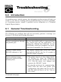
Introduction...................................................................... 73
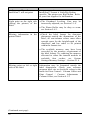
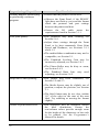
General Troubleshooting ................................................. 73
Error and Warning Messages........................................... 77
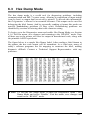
Hex Dump Mode ............................................................. 83
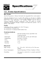
Specifications
7.0 Printer Specifications....................................................... 85
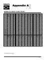
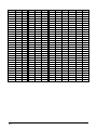
Appendix A
ASCII Control Code Chart...................................................... 89
Appendix B
Available Fonts and Bar Codes............................................... 91
Appendix C
Print Resolutions and Maximum Widths .............................. 101
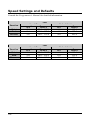
Speed Settings and Defaults.................................................. 102
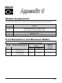
Module Assignments............................................................. 100
Appendix D
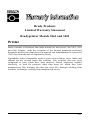
Warranty Information.............. Error! Bookmark not defined.
Glossary of Terms.................................................................. 107
Index ......................................................................................... 111
iii
iv
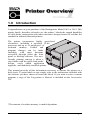
1.0
Introduction
Congratulations on your purchase of the Bradyprinter Model 2461 or 3481. This
printer family, hereafter referred to as ‘the printer’, blends the rugged durability
of solid-frame construction with other innovative design features to redefine the
standard in industrial thermal printers.
The printer incorporates highly specialized
electronics, including a powerful 32-bit
processor and up to 16 megabytes* of
on-board memory. Control and
program changes can be made
smoothly, with most functions
accessible through either the front
panel or labeling software. The userfriendly printing concept is taken a
step further with the quick-load media
design, easily added application
upgrades, and modularly installed options.
This manual provides all the information necessary to operate the printer on a
daily basis. To print labels or tags simply refer to the instructions included with
the software you have chosen to create the labels. If you wish to write a custom
program, a copy of the Programmer’s Manual is included on the Accessories
CD.
*The amount of resident memory is model dependent.
1
1.1
About this Printer
To meet all of your printing needs this unit is easily configurable. This section
lists the available standard and optional hardware features.
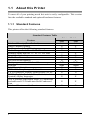
1.1.1 Standard Features
This printer offers the following standard features:
Standard Features Table
Feature
Printhead Density (Dots Per Inch)
Direct Thermal Printing
On-Demand and Batch Printing
Media Hanger for 1.5” and 3.0” I.D. rolls
Rotating Media Hub for 1.5” or 3.0” I.D. rolls
Simple media loading
Media Tear Bar
Fan-fold media handling
Flash programmable downloadable memory
SDRAM
RS-232 serial interface
IEEE 1284 Compliant parallel interface
2 X 20 Character, Liquid Crystal Display (LCD)
EFIGS (English, French, Italian, German, and
Spanish) display languages
AGFA Scalable font engine with CG Triumvirate
Scaleable and CG Triumvirate Bold Condensed
Font
Printhead Resistance Verification
2
Printer Model
2461
3481
203
300
X
X
X
X
X
X
X
X
X
X
X
X
1MB
2MB
8MB
16MB
X
X
X
X
X
X
X
X
X
X
X
X
1.1.2
Optional Features (available except as noted)
This printer offers the following optional features:
Light-Duty Cutter
A rotary-type cutter for cutting material with a maximum thickness of .005”
(.127mm).
Standard Cutter
A rotary-type cutter for cutting labels and tags with a maximum thickness of
.010” (.254mm).
Cutter Tray
For use with the optional cutter, this tray collects the cut labels and tags.
External Keyboard Support
Allows the connection of the Passport™ external keyboard.
Font Expansion Card (cannot be used with the I/O Expansion option)
A slide-in circuit card assembly with 8MB Flash memory expansion, adding
another module (configured in two 4MB partitions) for ILPC and/or additional
fonts and graphics. ILPC-International Language Printing Capability, consisting
of one of the following:
¾
¾
¾
CG-Times (Western European) Scalable
Kanji Gothic B Scalable font
Simplified Chinese GB Scalable font
Internal Media Rewinder
Available to rewind labels or backing material up to a six inch outer diameter
capacity and essential for use with the Peel and Present option.
I/O Expansion Card* (specify features at time of order)
A slide-in circuit card assembly with the following standard features:
¾
¾
General purpose (GPIO) interface for external printer and device control.
Time and Date (Real Time Clock) function.
And the following optional feature:
¾
8MB Flash memory expansion, adding another module (configured in two
4MB partitions) for ILPC and/or additional fonts and graphics.
3
LAN Interface
A slide-in circuit card assembly that provides network connectivity, allowing
multiple users on various platforms to share the same printer.
Peel and Present Mechanism (requires the Internal Rewind option)
A device used to automatically separate printed labels from the backing material
on-demand.
Present Sensor
A device to control the printer’s output, where subsequent printing occurs only
after the removal of a previously print label.
RS-422 Serial Interface*
Single-drop interface hardware to support greater distances from the host at
communication rates of up to 38,400 baud.
Thermal Transfer
This method uses ribbon to produce exceptional image clarity, as compared to
most direct thermal media types. This option can be ordered for use with either
‘coating in’ or ‘coating out’ type ribbons, and must be specified when ordering.
Twinax/Coax Interface
A slide-in circuit card assembly that provides connectivity to AS/400 and
System/3X Twinax host system or 3270-type host system. Cable included.
*These items are not available for the 2461 model printer.
4
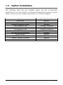
1.2
Option Installation
The following table lists the available options and the recommended
qualification level of the installer. For detailed information concerning a specific
option, contact your sales support representative or Technical Support.
Option
Cutter Tray
Cutters: Light and Standard Duty
Passport External Keyboard
Font Expansion Card
Internal Rewind
I/O Expansion Card
LAN Interface
Peel and Present Mechanism
Present Sensor
RS-422 Serial Interface
Thermal Transfer Assembly
Twinax/Coax Interface
Qualified Installer
Operator
Operator
Operator
Certified Technician
Operator
Certified Technician
Certified Technician
Operator
Operator
Certified Technician
Operator
Certified Technician
5
6
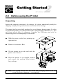
2.0
Before using the Printer
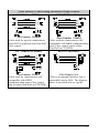
Unpacking
Inspect the shipping container(s) for damage; if evident, immediately notify the
shipping company to report the nature and extent of the damage.
The printer has been carefully packaged to avoid damage during transit. In order
to operate the printer, you will need to remove the packaging materials (i.e., tape
and foam) placed there for shipment. Complete the following steps prior to
connecting power or attempting to load media.
n
o
p
q
With the arrow on the box pointing up,
open the box.
Remove Accessories Box.
Tilt the printer on its side and slide the
printer out of its box.
Place the printer in an upright position
and remove the packing foam, plastic
bag, and tape.
; Note:
It is a good idea to save the carton and packaging materials in the
event that future shipment is ever required.
7
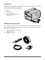
Inspection
After removing the printer from the packaging material, check the contents of
the package. In addition to this manual,
the following items should be included:
¾
¾
¾
¾
Printer
Power Cord
Accessories CD
Any special or additionally
purchased items.
Additional Requirements
The following items are necessary for generating and printing labels. Contact
your customer support representative for advice on which media and software
may best suit your needs.
¾
¾
¬
8
Serial or parallel interface cable
Applicable media
Applicable software
2.1
Choosing Media and Ribbon
The following is a limited overview of media characteristics. For complete
information and advice regarding your specific application needs, always
consult a qualified media specialist or a Media Representative.
Media Selection – Direct Thermal
Consider three important factors when selecting direct thermal stock:
•
The abrasive qualities of the material that covers the thermal reactive layer
of the paper.
•
The ability of that layer to control the chemical reaction that occurs when
the image is “burned”.
•
The amount of heat required to create an image on the paper.
Media Selection – Thermal Transfer
Consider three important factors when selecting thermal transfer media
combinations:
•
The label top coating and ribbon combinations affect image quality.
•
Ribbon backcoating is highly recommended. It provides protection for the
printhead and may also provide an anti-static coating.
•
Use a ribbon of equal or slightly greater width of the overall width of the
label (including the backing material).
2.1.1
Controlling Print Quality
The printer can provide maximum application flexibility with a comprehensive
set of print controls. The amount of heat applied per dot row and the rate at
which the paper moves under the printhead have the most effect on images that
are printed. The printer allows you to control these factors but also limits them
so you cannot ask the printer to print an image that could be damaging. For
example, low cost direct thermal stocks have very high reaction temperatures. It
takes high heat to make a clear image on this type of paper. There are four
methods of compensation:
•
The first is the ‘Media Type’ menu setting, which should be set to match the
media type (i.e., when printing with ribbon use the thermal transfer setting).
9
•
The second method, if only subtle contrast changes are desired, would be to
change the ‘Custom Adjustments / Darkness’ menu setting.
•
The next method would be to change the ‘Print Control / Heat’ menu
setting (also selectable as ‘Heat’ in most software programs). Increasing this
value causes more energy to be transferred to the media, resulting in a
darker image.
•
The final method would modify the ‘Print Control / Print Speed’ menu
setting (also selectable as ‘Print Speed’ in most software programs).
Reducing the print speed will allow the media to remain under the printhead
longer, and increasing the time for energy to be transferred.
You will find that printing fine images on less expensive direct thermal and
thermal transfer media at higher speeds can be tricky. At one heat setting, the
image will fade and at the next higher heat setting, the image will bleed. This is
because the reaction temperature of the media is so high that at higher rates of
speed, it cannot react fast enough. To print fine images at higher speed, media
with lower reaction or release temperatures are required. On the slower end of
the print rate settings, crisper images are possible because the media is not being
stretched beyond its limits.
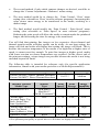
The following table is intended for reference only (for specific application
information, consult with your media specialist or a Media Representative).
Direct Thermal Media Type
Fasson 300 HD Direct Thermal Facesheet
Fasson 300 MD Direct Thermal Facesheet
Thermal Transfer
Media Type
Great Label TTL
Coated Paper,
Uncoated Paper, Tag
Stock, Some Films,
Some Synthetics
Coated Paper, Glossy
Paper, Tag Stock,
Some Synthetics, Films
Synthetics, Films
Print Speed*
Print Energy
10-12**
Medium
Ribbon
Print
Type
Speed*
10-12**
GPR Plus
MaxWax
IIMAK Versamark
Wax
2 - 10
Print
Image
Energy Durability
Medium Medium
Low
Low
Wax/Resin
2-8
Medium
High
Resin
4-6
High
High
*Values given in inches per second (IPS)
**For optimum print quality at speeds above 10 IPS these are highly recommended.
10
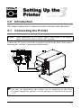
3.0
Introduction
This chapter explains how to connect the printer and load media and ribbon.
3.1
; Note:
Connecting the Printer
When connecting the AC power cord or data cables to the printer,
ensure the power switch is in the ‘Off’ position.
Connect the AC power cord to the receptacle located on the back of the printer,
then plug the cord into a properly grounded outlet.
) For
ease of connectivity, the printer can be connected to the Host
Computer though the parallel or serial interface, as described in Section
3.1.1.
11
3.1.1 Interfacing
The interface selection process in the printer occurs by data detection. Once
detected, the receiving port is set ‘active’. It will remain active, as long as data
flow continues; however, if data inactivity occurs and the Host Timeout Value
(see Section 4.1.5) is exceeded the selection process will automatically be
repeated. When timeout occurs before a complete label format has been
received, all data will be lost and the format must be sent again. To change an
active port immediately, cycle power ‘On’ and ‘Off’.
Parallel Port:
The parallel port interface has two menu selectable modes of operation: unidirectional or bi-directional. Uni-directional mode is forward channel
communication and requires a Centronics cable with a 36 pin male connector.
Bi-directional mode is IEEE 1284 Compliant, using forward and reverse
channel communications. In this mode, data can be sent to the host provided it
is also IEEE 1284 Compliant and has supporting software. This mode requires
is an IEEE 1284 cable with a Centronics 36 pin male connector.
Serial Port:
The serial port interface supports RS-232C and, if equipped, RS-422
communications. The list of printer settings below are menu selectable and be
set must match the host computer settings; see Section 4.1.5.
•
•
•
•
•
Baud Rate (communication speed)
Word Length
Word Parity
Number of Stop Bits
Handshaking Protocol
In addition to these settings, the serial interface cable must a have specific pin
configuration (pin-out) for proper data exchange. The different serial cables,
their respective pin configurations, suggested applications and part numbers are
shown on the next page (contact your reseller for ordering information).
12
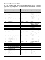
Serial Interface Cable Listing (all models except as noted)
Null Modem (MXM)
“PC” (DB9P) to Printer
Part Number 556000
Cable used for typical connection to
other DCE equipment with Xon/Xoff
flow control.
Part Number 556001
“PC” (DB25P) to Printer
Part Number 556002
Cable used for connection to a PC
compatible with DB25
communication ports. Flow control
can be either Xon/Xoff or CTS/DTR.
Cable used for connection to a PC
compatible with DB9P communication
ports. Flow control can be either
Xon/Xoff or CTS/DTR.
RS-422 Connection*
Part Number N/A
*This is an optional interface, but is
unavailable on the 2461. The diagram
above is provided only as a guide.
13
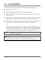
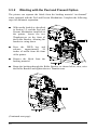
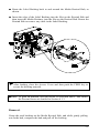
3.2
Loading Media
The following procedures explain the preliminary media loading steps.
n
o
p
q
r
Raise the Access Cover.
Rotate the Printhead Latch forward to raise the printhead.
Slide the Media Guide out away from the frame and then lower it to the
down position.
Referencing the drawings on the next page, determine the type of media
mounting device in the printer: Media Hanger or Rotating Media Hub.
If the printer is equipped with a Media Hanger, slide the Media Retainer
out, away from the frame and then lower it to the down position.
-OrIf the printer is equipped with the optional Rotating Media Hub, it can
accept two different core sizes: 3.0” (76mm) or 1.5” (38mm). When using
1.5” core media, first remove the 3.0” hub by grasping it and then pulling
firmly out and off. Store the removed hub in a safe place for future use.
; Note:
This printer is left justified. Always place the media against the
backstop when loading.
) Depending upon the type of media and printer options, several loading
methods are possible. All are detailed in the following sections.
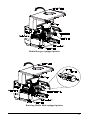
14
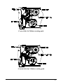
Media Hanger equipped printer
Rotating Media Hub equipped printer
15
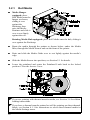
3.2.1
n
Roll Media
Media Hanger
equipped: place
Roll Media onto the
hanger as shown,
sliding it over
against the
Backstop; then
raise the Media
Retainer and slide it
over to rest firmly
against the roll.
Rotating Media Hub equipped: place Roll Media onto the hub, sliding it
over against the Backstop.
o
p
q
r
Route the media through the printer as shown below: under the Media
Idler, through the Media Sensor and out the front of the printer.
Raise and slide the Media Guide over to rest lightly against the media’s
edge.
Slide the Media Sensor into position; see Section 5.1 for details.
Lower the printhead and rotate the Printhead Latch back to the locked
position. Close the Access Cover.
) If you are printing with thermal transfer media, see Section 3.4 for ribbon
loading instructions.
) If you have a thermal transfer printer but will be printing on direct thermal
labels, see Section 4.1.1 for instructions to select direct thermal media in
the Media Settings menu.
16
3.2.2
n
o
p
q
r
s
Fan-Fold Media
Bring the media in through the Bottom or the Rear Media Slot.
Route the media as shown below: over the Media Hanger (or Rotating
Media Hub) when entering through the Rear Media Slot; or if entering
through the Bottom Media Slot, route the media over the Media Rewind
Hub.
Continue routing the media under the Media Idler, through the Media
Sensor and out the front of the printer.
Raise and slide the Media Guide (and Media Retainer if Media Hanger
equipped and using the Rear Media Slot) over to rest lightly against the
media’s edge.
Slide the Media Sensor into position; see Section 5.1 for details.
Lower the printhead and rotate the Printhead Latch back to the locked
position. Close the Access Cover.
) If you are printing with thermal transfer media, see Section 3.4 for ribbon
loading instructions.
) If you have a thermal transfer printer but will be printing on direct thermal
labels, see Section 4.1.1 for instructions to select direct thermal media in
the Media Settings menu.
17
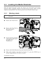
3.3
Loading the Media Rewinder
With the Media Rewinder option, the printer can wind labels and backing
material. When equipped with the Peel and Present option, labels can be
separated automatically. The following subsections illustrate both set-ups:
3.3.1
;Note:
n
o
p
q
r
Winding Labels
When winding labels, the outer diameter of the wound stock cannot
exceed 6”.
Remove the Front Fascia.
Remove the Tear Plate by
first removing the
Thumbscrew.
Position the Rewind Plate
on the printer and install
and tighten the
Thumbscrew.
Remove the Media Retainer from the Media Rewind Hub.
With media loaded as described in Section 3.2, press the FEED key to
advance approximately 20 inches of media.
(Continued next page)
18
s
t
u
Route the media back to the Media Rewind Hub as shown below.
Insert the edge of the labels into the Slot on the Rewind Hub and then
insert the Media Retainer into the Slot.
Slide the Media Retainer over the media and onto a Slot on the Media
Rewind Hub and rotate the hub to remove any slack in the Media.
) After loading, close the Access Cover and then press the FEED key to
secure the media.
Removal:
Grasp the printed labels on the Media Rewind Hub, and while gently pulling
out on the hub, compress the hub and pull off the labels.
19
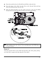
3.3.2
Winding with the Peel and Present Option
The printer can separate the labels from the backing material “on-demand”
when equipped with the Peel and Present Mechanism. Complete the following
steps for automatic separation:
n
o
p
q
With media loaded as described
in Section 3.2, and the Peel and
Present Mechanism installed on
the printer, loosen the two
Thumbscrews on the front of
the Roller Bracket, allowing the
bracket to swing down.
Press the FEED key and
advance
approximately
20
inches of media from the front
of the printer.
Remove the labels from the
backing material.
Route the backing through the Roller Bracket, as shown below; next, raise
the Roller Bracket and tighten the two Thumbscrews.
(Continued next page)
20
r Route the Label Backing back to and around the Media Rewind Hub, as
shown.
s Insert the edge of the Label Backing into the Slot on the Rewind Hub and
then insert the Media Retainer, into the Slot on the Rewind Hub. Rotate the
Rewind Hub to remove any slack in the Label Backing.
) After loading, close the Access Cover and then push the FEED key to
secure the backing material.
;Note:
To print on-demand, load the media as described above, and enable
the Present Sensor as detailed in Section 4.1.3.
Removal:
Grasp the used backing on the Media Rewind Hub, and while gently pulling
out on the hub, compress the hub and pull off the backing.
21
3.4
;Note:
Loading Ribbon
Always use ribbon slightly wider than the media backing material;
this helps protect against printhead wear.
To produce an image on the label, thermal transfer media requires ribbon.
Ribbon types are available with the ‘ink’ layer on the outside (coating side out)
or with the ‘ink’ layer on the inside (coating side in). These types cannot be
interchanged in the printer. Arrows on the Ribbon Supply Hub are used to
indicate the correct direction of ribbon travel (see the next page for examples).
To load a ribbon:
n
o
p
q
r
s
t
u
Raise the Access Cover.
Rotate the Printhead Latch forward and raise the printhead.
Depending upon the directional arrows of the Ribbon Supply Hub (see the
next page for examples), mount the ribbon so that it is dispensed in the
appropriate direction for the ribbon type.
Slide the ribbon on completely to rest against the flange.
Route the ribbon under the Ribbon Roller then out the front of the printer.
Continue routing the ribbon up to and around the Ribbon Take-Up Hub, as
shown. Wind the ribbon around several times in a clockwise direction to
secure it in place.
Lower the printhead and rotate the Printhead Latch back to the locked
position. Close the Access Cover.
With the printer ‘On’ press and hold the FEED button for three seconds to
position the media for printing; see Section 5.2 for details.
Removal:
Pull the empty core from the Ribbon Supply Hub and discard it. Next, grasp
the used ribbon on the Ribbon Take-Up Hub, while gently pulling out on the
hub, compress the hub to pull off the used ribbon.
22
‘Coated Side In’ Ribbon routing path
‘Coated Side Out’ Ribbon routing path
23
24
4.0
Front Panel Operation
The front panel is equipped with five keys, 3 indicators and a Liquid Crystal
Display (LCD). The key functions differ depending upon the selected mode. The
selectable modes are Ready, Menu and Quick Test.
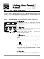
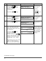
4.0.1
Ready Mode: Normal Operation (Ready Light ‘On’)
n
Pressing the PAUSE key temporarily suspends
printing. Pressing again returns the printer to
normal operation.
o
The FEED key advances one label, and clears any
faults that have been corrected.
Pressing and holding this key 4 seconds will
calibrate the label position.
p
The CANCEL key cancels a job and ‘Pauses’ the
printer.
Pressing and holding this key 4 seconds will reset
the printer and clear temporary host settings.
q
The MENU key toggles between the Ready and
Menu Modes.
In the Ready mode, pressing and holding 4 seconds
will change the display contrast.
r
Pressing the TEST key enters the Quick Test Menu.
25
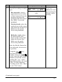
4.0.2
Menu Mode: Configuration (Ready Light ‘Flashing’)
n
The DOWN ARROW key moves to the previous
(reverse) menu item; also, decrements numerical
values within certain menu selections.
o
The UP ARROW key moves to the next (forward)
menu item; also, increments numerical values
within certain menu selections.
p
The ENTER key selects function or value
displayed in the LCD (selection is indicated with
an ‘*’); also, moves between selections in multiple
parameter fields.
q
The ESCAPE key moves to the previous menu
level, and finally back to the READY mode.
26
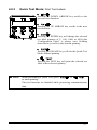
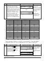
4.0.3
Quick Test Mode: Print Test Labels
n
Pressing the DOWN ARROW key scrolls to the
previous test function.
o
Pressing the UP ARROW key scrolls to the next
test function.
p
Pressing the ENTER key will change the selected
test label quantity of 2, 100, 1000, or 9999 (the
‘Configuration Label’ is always one). Holding
down the key scrolls to the desired quantity.
q
Pressing the ESCAPE key will exit the Quick Test
Mode without printing.
r
Pressing the TEST key will print the selected test
label at the selected quantity.
; Notes:
When performing a Quick Test, press
to abort printing.
or
The test functions are disabled while processing communications
data.
27
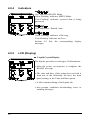
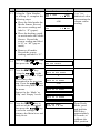
4.0.4
Indicators
n
‘On’ indicates READY Mode.
‘Slow Flashing’ indicates MENU Mode.
‘Fast Flashing’ indicates received data is being
processed.
o
‘On’ indicates a ‘Paused’ state.
p
‘Slow Flashing’ indicates a Warning.
‘Fast Flashing’ indicates an Error.
Section 6.2 lists the corresponding display
messages.
4.0.5
LCD (Display)
n Liquid Crystal Display
The display provides several types of information:
• After the power on sequence is complete, the
READY message.
• The time and date, if the printer has received it
from one of the following: the host, the front
panel setting, or the Time and Date option.
• A label counter during a batch print job.
• Any prompt, condition, downloading, error, or
warning messages.
28
4.0.6
Factory Default Resetting
Depending upon the method used, there are two factory default reset levels
possible:
;Note: See Section 4.1 for the factory default settings.
Level 1: To return the printer to factory default settings only: press and hold the
PAUSE and CANCEL keys; continue to depress the keys until the
‘SYSTEM RESET’ message flashes.
Level 2: Highest level; will return the printer to factory default settings, and
will reset all calibration and adjustment parameters, to execute: press
and hold the PAUSE, FEED, and CANCEL keys; continue to depress
the keys until the ‘SYSTEM RESET’ message flashes.
;Note: After performing a Level 2 Reset, the printer requires that
both Ribbon and Media Calibrations be performed; see
Sections 5.2 and 5.3.
29
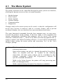
4.1
The Menu System
The printer operation can be controlled through the menu system user interface,
allowing the operator access to these six menu branches:
•
•
•
•
•
•
Media Settings
Print Control
Printer Options
System Settings
Communications
Diagnostics
Changes made in the menu system can be saved, so that the configuration will
not be lost if power is removed. And as a security feature, and to prevent
accidental changes, the user interface has a password protection feature.
The same functional commands from the host computer may, in some cases,
override the printer’s menu settings. If the host sends a reset command, the
current configuration (including host changes) will be saved. The current
selection is indicated with a ‘*’ on the LCD, while selections designated with ‘§’
require a printer reset before becoming effective. A reset will be automatically
invoked upon exiting the menu system and answering ‘Yes’ to the ‘Save
Changes’ prompt.
; Notes: The factory default settings are denoted with the ‘’ symbol in the
following subsections.
Some menu settings can only be changed through the Front Panel.
These are denoted with the ‘♦’ symbol in the following
subsections. All other menu settings can be overridden by host
software commands. Consult the Programmer’s Manual for
specific command information.
While in the Menu System, the printer will stop processing new
DPL (or bitmapped) data.
While communicating, the Quick Test function is disabled.
30
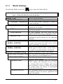
4.1.1
Media Settings
From Ready Mode, press the
; Note:
key to enter the Menu Mode.
Entering the menu will clear memory of any settings sent from the
host – unless the host has reset the printer.
Selects a print method.
MEDIA TYPE
For use with heat sensitive media.
DIRECT THERMAL
THERMAL TRANSFER For use with media requiring a ribbon to
create an image.
SENSOR TYPE
GAP
CONTINUOUS
REFLECTIVE
Selects the top-of-form (TOF) sensing
method for the media.
The printer recognizes the TOF by sensing
gaps in the media.
No TOF sensing. The user must use the
LABEL LENGTH setting to determine TOF.
The printer recognizes the TOF by sensing
registration (black) marks on the underside
of media.
LABEL LENGTH
04.00in (0-99.99)
For use with continuous media. Label length
is used to determine the TOF when ‘Sensor
Type-Continuous’ is selected.
MAXIMUM LABEL LENGTH
16.00in (0-99.99)
Sets the maximum length between TOF
marks (gap or black stripe). If this limit is
exceeded, a top of form fault is declared.
Adjusts the printer to sense your media.
SENSOR CALIBRATION ♦
PERFORM CALIBRATION The User enters the empty, gap or mark and
paper values to set the media sensor.
User directly inputs the best gain values to
ADVANCED ENTRY
adjust the media sensor.
SENSOR GAIN
Observe A/D reading and set SENSOR
GAIN. Adjusts the sensitivity of the sensor
for custom label stock. Higher gain means
more sensitivity; however, when set too high
the printer loses the ability to distinguish
gap or mark from paper.
SENSOR LEVELS
Sets threshold values for the media sensor
parameters. Entry for paper, gap/mark, and
empty thresholds.
31
4.1.2
Print Control
HEAT
10 (0-30)
Controls the printhead ‘burn-time’. See
Section 2.1.1 for more on print quality control.
PRINT SPEED
2-12 in/sec
Controls the rate of label movement during the
printing process; see Appendix C.
FEED SPEED
2-12 in/sec
Controls the rate of label movement between
printing areas; see Appendix C.
REVERSE SPEED
2-6 in/sec
Controls the rate of label movement during
backup positioning for start of print, cutting or
present distance; see Appendix C.
ROW OFFSET
00.00in (0-99.99)
Shifts the vertical start of print position. This
is the user setting for row adjustment.
COLUMN OFFSET
00.00 in (0-99.99)
Shifts the left-justified horizontal start of print
position to the right.
LABEL WIDTH
1.00-4.16 inches
Sets the maximum limit for the printable
surface width. Images or data beyond this limit
will not print; see Appendix C.
PRESENT DISTANCE
0.00 in (0-4.00)
Specifies an additional amount to advance the
label after printing. When the next label
format is received, the printer backfeeds to the
start position. Only the last label of the batch
will be presented if the present sensor is not
enabled.
CUSTOM ADJUSTMENTS These factory adjustments independently
change listed parameters, negating slight
♦
mechanical differences sometimes evident
when multiple printers share the label formats.
Controls the printhead strobe time to fineDARKNESS
tune the HEAT setting.
XX
(1-64)
Shifts the vertical start of print position
ROW ADJUST
upward in dots to fine-tune the ROW
XXX DOTS (1-128)
OFFSET setting; see Appendix C.
;
Note: A Positioning Calibration must be
performed before this parameter takes
effect; see Section 5.2.
COLUMN ADJUST
XXX DOTS (1-128)
PRESENT ADJUST
XXX DOTS (1-128)
32
Shifts both the horizontal start of print
position and the LABEL WIDTH termination
point to the right in dots to fine-tune the
COLUMN OFFSET setting; see Appendix C.
Adjusts the label stopping position in dots to
fine-tune the PRESENT DISTANCE setting;
see Appendix C.
4.1.3
Printer Options
MODULES
PRINT DIRECTORY
PRINT FILE
FORMAT MODULE
DELETE FILE
PACK MODULE
PRESENT SENSOR
ENABLE
DISABLE
NOT INSTALLED
CUTTER
ENABLE
DISABLE
NOT INSTALLED
The physical presence of the respective
memory module must be detected to show the
module function selections for that module in
the menu system.
Prints a label directory of all available
modules, the available space on these
modules, the files present, and the type of
module and files.
The user may select from a list of available
files for printing.
The user may select from a list of available
modules for formatting – all data will be
erased.
The user may select from a list of available
files for deleting.
Packing the module removes files marked as
deleted and defragments existing files
structures to recover space.
Used for on-demand label dispensing, where
a printed label blocking the sensor will
inhibit the further printing until removed. The
physical presence of the Present Sensor must
be detected to show the ENABLE/DISABLE
selections in the menu system.
Enables the sensor for on-demand printing.
Disables the sensor.
No sensor can be detected.
Physical presence of a cutter must be
detected to show the ENABLE/DISABLE
selections in the menu system.
Enables the cutter for label cutting.
Disables the cutter.
No cutter can be detected.
33
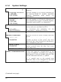
4.1.4
System Settings
MEMORY SETTINGS ♦
Allows user to allocate use of printer
memory.
Sets the number of 1K blocks allocated for
the internal RAM ‘D’ module. Available
memory dependent upon model; see
Appendix C.
SCALEABLE FONT
CACHE
0312 KB
(100-16384)
Sets the number of 1K blocks allocated for
the scaleable font engine. Available memory
dependent upon model; see Appendix C.
INTERNAL MODULE
1024 KB
(100-16384)
SYMBOL SET SELECT
PC_850
MULTILINGUAL
Selects the code page used by the printer
unless otherwise specified in DPL.
29 selections are standard, see the
Programmer’s Manual for details.
DATE AND TIME
Allows the user to set Date/Time.
MEDIA COUNTERS
Internal record of inches printed and time
in use.
Shows the number of inches printed and
number of hours of the printer has been
powered ‘On’ since being set at the factory.
Not resettable by the user.
The number of operational hours and
inches printed from the date last reset.
User may reset.
Resets the resettable counters to zero.
ABSOLUTE
COUNTER
RESETTABLE
COUNTER
RESET COUNTER
PRINT CONFIGURATION
Prints the effective configuration of the
system. In addition, if settings were changed
that require a reset to become effective, this
will be indicated with the ‘§’ symbol.
A ‘•’ symbol next to the printed item
indicates that it was changed via the host
but not saved in non-volatile memory
(Continued next page)
34
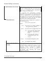
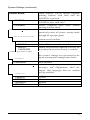
System Settings (continued)
CONFIGURATION LEVEL
PRINTER KEY
Note: Reserved for future use – current
printer configuration does not allow these
values to be modified. This information
may change at a later date.
To upgrade the application (resident
software) of the printer, the hardware and
software compatibility levels must match for
the update to be accepted. This information
is displayed here and can also be found
printed on the configuration label.
Each printer has a unique KEY number in
the following form:
vvvv-wwxx-yyyyyy-zzz
where:
vvvv – represents the model number of
the application loaded
wwxx – represents the configuration level
ww
represents the main board
hardware compatibility
level
xx
represents the software
compatibility level (see
below)
yyyyyy – is a manufacturing date code
zzz – is a unique time stamp
UPGRADE PRINTER
CODE
The application version may only be
updated with a configuration level of equal
or lesser value than the software level;
however,
the
printer’s
software
compatibility level can be increased by
purchasing and entering the proper
upgrade code here.
(Continued next page)
35
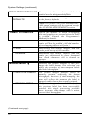
System Settings (continued)
SET FACTORY DEFAULTS Parameters in this menu listing with the ‘ ’
symbol are the designated defaults.
Overwrite the current settings and restore
SET FACTORY
to the factory defaults.
DEFAULTS
Note: The printer will reset automatically.
ALL menu settings will be restored except
the CUSTOM ADJUSTMENTS section.
FORMAT ATTRIBUTES
TRANSPARENT
XOR
OPAQUE
IMAGING MODE ♦
MULTIPLE LABELS
SINGLE LABELS
(Continued next page)
36
Affects the manner in which overlapping
text and graphics are treated when the label
is printed. Consult the Programmer’s
Manual for details.
Intersecting text strings, images and bar
codes will not be printed. (An odd number
of overlapping objects will print.)
Intersecting text strings, images, and bar
codes print on top of one another.
Interacting text strings, images, and bar
codes are obliterated by those formatted
last. Each character cell is treated as
opaque.
Instructs the printer whether it can preimage the label format. This selection can
affect the accuracy of time-stamped labels
and label throughput.
The printer images multiple labels as
memory permits, achieving the fastest
throughput; however if time-stamping, the
time will reflect the moment the label is
imaged rather than when actually printed.
The printer images the next label only after
the previous label has been successfully
printed; this single processing provides
more accurate time-stamps with a minor
cost to label throughput.
System Settings (continued)
PAUSE MODE
ENABLE
DISABLE
SECURITY ♦
SELECT SECURITY
ENABLE
DISABLE
MODIFY
PASSWORD
UNITS OF MEASURE
METRIC
IMPERIAL
SELECT LANGUAGE ♦
ENGLISH
FRENCH
GERMAN
SPANISH
ITALIAN
When enabled, PAUSE MODE suspends
printing between each label until the
PAUSE key is pressed.
Printer requires operator to press the
PAUSE key after each label.
Printer completes label batch without
pausing between labels.
Provides the user with the ability to
password protect all printer settings made
through the operator panel.
Enable or disable the front panel menu
system security lockout
Selecting this enables password protection.
No protection.
Modify the password required to access the
front panel menu when security is enabled.
Selects the measurement system in which
the system’s settings are represented in the
menu system and on configuration labels.
Metric standard
Inch standard
Selects the language in which the display
messages and configuration label are
shown. Only languages that are resident
will be available.
English
French
German
Spanish
Italian
37
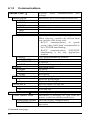
4.1.5
Communications
SERIAL PORT ♦
BAUD RATE
38400
28800
19200
9600
4800
2400
PROTOCOL
BOTH
SOFTWARE
HARDWARE
NONE
PARITY
NONE
ODD
EVEN
DATA BITS
7
8
STOP BITS
1
2
PARALLEL PORT ♦
PORT DIRECTION
UNI-DIRECTIONAL
BI-DIRECTIONAL
(Continued next page)
38
Controls serial communications port
settings.
Determines the serial communication rate.
9600 bits per second
Sets the flow control (handshaking) method.
When selecting, consider the desired baud
rate and the cable being used:
RS-232 communications, at speeds
greater than 9600 baud recommended to
use CTS/DTR handshaking.
RS-422 communications, XON/XOFF
handshaking is the only appropriate
method.
Uses both handshaking methods
XON/XOFF
CTS/DTR
No handshaking is used
Sets Word parity
No parity
Odd parity
Even parity
Sets Word length
Seven bit Word length
Eight bit Word length
Sets the number of stop bits
One stop bit
Two stop bits
Controls parallel port settings.
Determines if messages are sent from the
printer to the host via the parallel port.
One-way printer communication.
Enables IEEE 1284 back channel
operation.
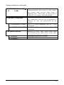
Communications (continued)
HOST TIMEOUT VALUE ♦
10
(1-60)
The number of seconds an active
communications port must be idle before
the printer may process data from a
different port. This value is also used to
“timeout” an image / label download.
CONTROL CODES ♦
Allows the operator to change the prefix of
the commands listed in the Programmer’s
Manual, as they are interpreted by the
printer.
STANDARD CODES Hex 01 = SOH command; Hex 02 = STX
command
ALTERNATE CODES Hex 5E = SOH command; Hex 7E = STX
command
FEEDBACK MODE
ENABLE
DISABLE
Returns a 0x30, [RS], after each label
successfully prints, and a 0x31, [US], after
each batch of labels in printed.
Feedback characters are sent.
No feedback characters are sent.
39
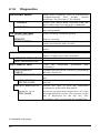
4.1.6
Diagnostics
HEX DUMP MODE
ENABLE
DISABLE
OPTIONS TESTING
TEST PRESENT
SENSOR
TEST CUTTER
PERFORM TEST
TEST INPUT/OUTPUT
Mode most commonly used to troubleshoot
communications and format related
problems. See Section 6.3 for details.
Prints raw ASCII data received from the
host rather than executing the commands.
Executes and prints label formats (normal
operating mode).
Tests currently installed options
Performs a functional test of the Present
Sensor circuitry.
Performs a functional test of the optional
cutter mechanism and circuitry.
Selectable number of test cuts: 1, 10, or 100
times.
Tests the optional GPIO (General Purpose
Input / Output) port when installed.
MONITOR GPIO INPUT
TEST GPIO OUTPUT
DOT CHECK TEST
Tests the individual printhead dots
(elements).
Updates the dot check results by performing
PERFORM DOT
the dot check test.
CHECK
DOT CHECK RESULTS Displays the current results of the dot check
test.
XXXX OF YYYY
Displays the ratio of dots tested which
TESTED GOOD
passed.
Allows the user to view the individual
INSPECT BAD DOTS
resistances of the dots that failed.
XXXX OF YYYY
Press the forward and reverse keys to scroll
ZZZZ OHMS
through detailed results. The position of the
dot is displayed on the top line. The
resistance value is given on the second line.
(Continued next page)
40
Diagnostics (continued)
All Analog Sensor readings displayed
SENSOR READINGS
THR TRAN RIBM 24V-> Live sensor values may be viewed. View is
toggled with forward and reverse keys.
255 255 255 255
Maximum values are shown here (actual
values may vary) for the following:
thermistor sensor, transmissive (gap) media
sensor, ribbon motion sensor, 24 volt power
supply sensor
(Continued) present sensor, head down
<- PS HD RANK
sensor (n/a), printhead ranking resistor.
255 255 255
RIBBON SENSOR LIMITS♦ Displays ribbon sensor ADC low and high
values. A Level 2 reset is required to change
these values.
Approximate default values are shown here
RIBBON ADC HIGH =
(actual values will vary following a
104
Positioning Calibration; see Section 5.2).
RIBBON ADC LOW =
070
41
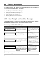
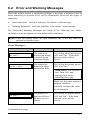
4.2
Display Messages
The printer generates and displays four different categories of information (if
not in the Menu system or Quick Test Mode):
¾
¾
¾
¾
User Prompts and Condition Messages
Download Messages (see Section 5.7)
Error Messages (see Section 6.2)
Warning Messages (see Section 6.2)
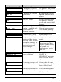
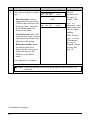
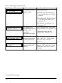
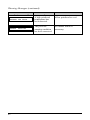
4.2.1
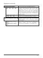
User Prompts and Condition Messages
User Prompts indicate a required user operation. Condition Messages indicate a
current printer operation or state, when outside the menu system.
User Prompts and Condition Messages:
Displayed Message
Description
Condition(s)
"
"
The printer is trying to
clear a fault condition.
Occurs when the FEED
key is pressed to clear an
error.
"
#"
A calibrated feed
operation is being
performed.
The FEED key is
depressed for several
seconds or during any
feed operation when the
printer has lost TOF.
" #`
^ The CANCEL or TEST
key was pressed during
a batch job.
The current print batch
will be cancelled if
ENTER is pressed; the
remaining labels will not
be printed.
"
;;;;
Security protection is
enabled on the printer.
Provide the correct userdefinable password to
proceed.
You are attempting to
enter MENU Mode;
however, a password
entry is required for
access.
(Continued next page)
42
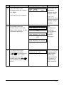
Displayed Message
Description
Condition(s)
"
The printer is paused
or / offline.
The printer is in a paused
condition.
The print job is being
processed.
Batch status indication,
updated with each label
printed.
READY Mode.
Normal operating mode.
The printer is ready to
receive and process label
formats.
The Present Sensor
option is enabled and a
printed label is
awaiting removal.
A label blocks the
Present Sensor; remove
it to continue printing.
You are now exiting
the menu, but have
made changes to the
settings of the printer.
Pressing ‘ENTER’ will
save these changes; if
not, the printer will
revert to previously
saved settings.
Menu changes have
affected the
configuration of the
printer.
"
Normal power-up / soft
reset condition.
Follows the ‘SYSTEM
RESET IN
PROGRESS’ message
after a reset or powerup.
Normal power-up / soft
reset condition.
Occurs when the user
resets the printer via the
host or Front Panel.
"
#"
The printer contains an
invalid calibration.
Perform calibration to
remove the condition.
See Section 5.
"
"#
" "
^ ;Note: If changes
have been made that
require a printer reset,
the printer will
automatically invoke
that reset.
43
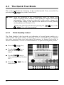
4.3
The Quick Test Mode
This section explains the functions of the resident Quick Tests, accessible by
pressing the
key on the Front Panel.
; Notes:
With the exception of the Configuration Label, all Quick Test
labels require 4-inch (102mm) wide media to capture all format
information. When using less than full width media, change the
Label Width setting to the width of the material to avoid printing
on the platen (see Section 4.1.2).
During any Quick Test Label run, pressing the
key will abort printing.
4.3.1
key or the
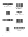
Print Quality Label
The Print Quality Label provides an indication of overall print quality at a
selected heat and speed setting. Consisting of fence and ladder type compliant
bar codes, assorted font sizes and graphic fill patterns, its format can be used to
ensure conformance, as well as visual aesthetics. To print a Print Quality Label:
n Press the
o Use the
key.
key to
scroll to ‘Print Quality
Label’.
p Use the
key to
select a quantity; see Section
4.0.3.
q Press the
start printing.
44
key to
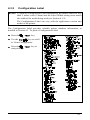
4.3.2
Configuration Label
;Notes: To print all Configuration Label information, the media cannot be less
than 2 inches wide (51mm) and the Label Width setting must match
the width of the media being used (see Section 4.1.2).
The Configuration Label can vary with the application version and
model of the printer.
The Configuration Label provides valuable printer database information, as
detailed in Section 4.1. To print a Configuration Label:
n Press the
o Use the
key.
key to scroll
to ‘Print Configuration’.
the
p Press
start printing.
key to
45
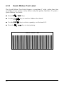
4.3.3
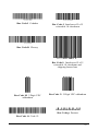
Quick Ribbon Test Label
The Quick Ribbon Test Label features a compliant 4” wide, picket-fence bar
code that can be used to verify ribbon and print quality functions. To print a
Quick Ribbon Test Label:
n Press the
o Use the
p Use the
q Press the
46
key.
key to scroll to ‘Ribbon Test Label’.
key to select a quantity; see Section 4.0.3.
key to start printing.
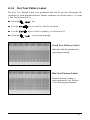
4.3.4
Dot Test Pattern Label
The Dot Test Pattern Label tests printhead and can be used to determine the
condition of each thermal element. Pattern examples are shown below. To print
a Dot Test Pattern Label:
n Press the
o Use the
p Use the
q Press the
key.
key to scroll to ‘Dot Test Pattern’.
key to select a quantity; see Section 4.0.3.
key to start printing.
Good Test Pattern Label:
Indicates that the printhead is
operating normally.
Bad Test Pattern Label:
Streaks indicate a dirty or
faulty printhead. See Section
5 for cleaning instructions.
47
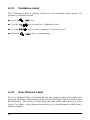
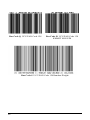
4.3.5
Validation Label
The Validation Label is another useful tool for evaluating print quality. To
generate a Validation Label:
n Press the
o Use the
p Use the
q Press the
4.3.6
key.
key to scroll to ‘Validation Label’.
key to select a quantity; see Section 4.0.3.
key to start printing.
User Defined Label
The User Defined Label will reprint the last label printed (unless the printer was
powered-off between the printing of the last label and the request to print a user
defined label). This label is recalled from the print buffer and can be any of the
Quick Test labels, a label format from the host, or a label format recalled from a
memory module.
48
5.0
Introduction
Correct hardware adjustments, regular maintenance, and calibrations will ensure
continued peak printer performance.
5.1
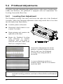
Media Sensor Adjustment
The laterally adjustable Media Sensor is used to detect media; it also detects
label TOF for all media types, except continuous stock (where TOF is
determined by the label format). To properly detect TOF, the gap, notch, or
black mark must pass under the Sensor Eye Mark, as noted in the table below. If
messages such as “Out-Of-Stock” or “Top-Of-Form” appear, the sensor’s
position may need adjustment.
Media Type*
Media Sensor Adjustment
Selected Sensing Method Sensor Eye Mark Position
Standard die-cut
Circular die-cut
Notched
Reflective
Continuous
Gap
Gap
Gap
Reflective
Continuous
Near the middle of the label
Directly over the apex
Directly over the notch
Directly over the black mark
Near the middle of the label
*See Section 1.3.2 for an explanation of the media requirements.
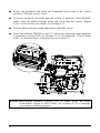
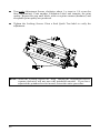
To adjust the Media Sensor:
n
o
The printer powered ‘On’, media loaded, and the access cover open, rotate
the Printhead Latch forward to raise the printhead.
After ensuring that the media is passing through the Media Sensor, position
the Sensor Eye Mark over the label’s TOF mark (see drawing next page) by
grasping and moving the Slide Tab ‘in’ or ‘out’.
(Continued next page)
49
p
q
r
s
Lower the printhead and rotate the Printhead Latch back to the locked
position. Close the Access Cover.
If you are using die-cut media proceed to Step 6; otherwise, from READY
mode, enter the Media Settings menu and verify that the correct ‘Sensor
Type’ is selected for your media; see Section 4.1.1.
Exit the Media Settings menu and return to READY mode.
Press and hold the FEED key until 2-3 labels are advanced (approximately
4 seconds) to set the TOF; see Section 5.2. If ‘Uncalibrated’, ‘Top of Form
Fault’, or ‘Position Error, is displayed go to Section 5.3.
; Note: Start-of-print
distance changes can be made using the Print
Control/Row Adjust or Row Offset (see Section 4.1.2) or through
your software labeling program.
50
5.2
Positioning Calibration
The Positioning Calibration sets the TOF and calculates the label length of the
media. This process also calibrates the ribbon sensor on printers equipped with
the thermal transfer option.
If using die-cut and reflective media, this procedure is recommended:
1) When a ‘Position Fault’ or ‘Ribbon Fault’ message is displayed.
2) After changing media.
3) Following a Media Sensor Calibration.
If using continuous media, TOF and label length parameters are set by the label
format. So this procedure should be performed to recalibrate the ribbon sensor
and is recommended:
1) When a ‘Ribbon Fault’ message is displayed.
2) Following a Media Sensor Calibration.
To perform a Positioning Calibration:
Step
Operator Action
1
Turn ‘On’ and enter the media setup parameters in the Media Settings
Menu; see Section 4.1.1. (If a ‘Ribbon Fault’ is indicated, first perform a
Level 2 reset; see Section 4.0.6.)
2
Load media (and ribbon, if equipped with the thermal transfer option);
see Sections 3.2 and 3.4. Calibrate the Media Sensor; see Section 5.3.
3
Press and hold the FEED key for approximately 4 seconds or until 2-3
labels advance. Upon completion, the ‘Ready’ message will be displayed.
5.3
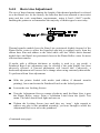
Media Sensor Calibration
Media Sensor calibration should be performed during initial printer setup, if
switching media types, or if an ‘Uncalibrated’ message is displayed. To ensure
that each label is detected correctly and reliably, two different methods are
available to calibrate the printer: Standard and Advanced Entry.
5.3.1
Standard Calibration
The first calibration method is appropriate for most media types. The printhead
is raised for visual access to the media; corresponding sensor readings are
displayed to provide an indication of the best sensor position over the media, a
51
position that can become critical when using reflective or notched stock with a
small TOF mark. Three required readings are:
Empty:
No media in the Media Sensor.
Mark or Gap: Only the backing (liner) material, notch, or reflective mark in the
sensor.
Paper:
With an unmarked label area (a space without pre-printing) in the
sensor.
To perform a Standard Calibration:
Step
1
Operator Action
Turn ‘On’ the printer.
2
Press the
Menu Mode.
key to enter
Displayed Message
"
Comment
Wait until
‘Ready’ is
displayed.
" See Section
4.0.2 for
details.
Lift the printhead for visual
access to the Media Sensor
and load label media.
3
Press the
key to
enter the Media Settings
menu.
" " See Section
4.1.1 for
details.
4
Press the
" See Section
4.1.1 for
details.
5
Press the
key. Use
the
key to scroll
to the desired sensor type
and press the
key
to enable the selection.
J"
See Section
4.1.1 for
details.
(Continued next page)
52
key.
The enabled
selection will
be indicated
with an *.
Step
6
Operator Action
Displayed Message
Press the
key. Use " "
#"
the
key to scroll
to ‘Sensor Calibration’.
Comment
See Section
4.1.1 for
details.
Press the
key to
abort this
procedure.
7
Press the
8
Press the
key.
"# Ensure no label media is in " ]<<<_
the Media Sensor then press
any key.
key.
"
#"
"
#"
See Section
4.1.1 for
details.
Sets the
parameter for
the ‘out of
stock’
condition.
‘yyy’ is a
numerical value
representing the
current sensor
reading.
(Continued next page)
53
Step
9
Operator Action
Displayed Message
Comment
Proceed according to media " #"
" ]<<<_
type:
Sets the
parameter for
the ‘gap’ or
‘mark’ value.
-ORDie-cut stock: remove
approximately six inches
of label material from the " "
backing (liner) and place " ]<<<_
the backing under the
Sensor Eye Mark.
Notched stock: place the
notched area in the sensor
and adjust the Sensor Eye
Mark over the notch.
Reflective media: place
the black mark (face
down) in the sensor and
adjust the Sensor Eye
Mark over the black
mark.
‘yyy’ is a
numerical value
representing the
current sensor
reading.
If the ‘Sensor
Type’ is set to
‘Continuous’,
this step is
skipped, going
directly into
Step 10.
Press any key to continue.
; Note:
After the Media Sensor has been adjusted do not move its
position.
(Continued next page)
54
Step
Operator Action
10 Place the label (and
backing) under the Sensor
Eye Mark.
Displayed Message
" "
" ]<<<_
Press any key to continue.
11 Depending upon the
‘Sensor Type’ selection,
observe the display for the
calibration message.
Comment
Calculates the
parameter
settings for the
‘Paper’ value.
‘yyy’ is a
numerical value
representing the
current sensor
reading.
" "
#"
-OR
"
#"
-OR-
See
‘Calibration
Problems’
(listed below)
for other
possible
messages.
"
#"
12 Exit upon successful
calibration: press the
key to back out
of the menu tree, when
prompted to save the
settings press the
key to return to the Main
Menu.
" "`
^ After saving the
settings, press
and hold the
FEED key,
approximately
4 seconds, to
calibrate the
label position.
55
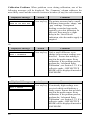
Calibration Problems: When problems occur during calibration, one of the
following messages will be displayed. The ‘Comment’ column addresses the
most likely cause and the corrective action to be taken (if any) for each situation.
Displayed Message
" "
#"
Action
Comment
Press any key. The printer measured only a small
difference between the ‘empty’ and
‘gap’ readings. Transparent
backing or notched type media
typically gives this indication. In
this case, there may be a slight
delay in the ‘Out of Stock’
indication, after the media supply is
emptied.
Or:
Displayed Message
" " "
#"
Action
Comment
Press any key. Only a small difference or no
change in low sensor readings was
detected. Ensure that nothing is
stuck in the media sensor. Retry
calibration. If the problem persists,
perform the ‘Advanced Entry
Calibration’; see Section 5.3.2. If in
reflective mode – REFLECTIVE
MODE will be displayed instead of
GAP MODE.
Or:
Displayed Message
" " 56
Action
Comment
Press any key. Consistently high readings were
received which could indicate a
faulty sensor. Ensure that no labels
stuck in the media sensor. Retry
calibration. If the problem persists,
perform the ‘Advanced Entry
Calibration’; see Section 5.3.2. If in
reflective mode – REFLECTIVE
MODE will be displayed instead of
GAP MODE.
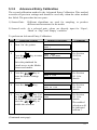
5.3.2
Advanced Entry Calibration
The second calibration method is the Advanced Entry Calibration. This method
overrides all previous settings and should be used only when the other method
has failed. The procedure has two parts:
1) Sensor Gain:
Different algorithms are used for sampling, to produce
different measurements for the media.
2) Sensor Levels: At a selected gain, values are directly input for ‘Paper’,
‘Mark’ or ‘Gap’, and ‘Empty’ variables.
To perform an Advanced Entry Calibration:
Step
1
Operator Action
Turn ‘On’ the printer.
2
Press the
Menu Mode.
key to enter
Displayed Message
Comment
"
" See Section
4.0.2 for
details.
Raise the printhead for
visual access to the Media
Sensor and media.
3
Press the
key to
enter the Media Settings
menu.
" " See Section
4.1.1 for
details.
4
Press the
" See Section
4.1.1 for
details.
5
Press the
key. Use
the
key to scroll to
the desired sensor type and
press the
key to
enable the selection.
J"
See Section
4.1.1 for
details.
key.
The enabled
selection will
be indicated
with an *.
(Continued next page)
57
Step
6
Operator Action
Press the
key.
key to
Use the
scroll to ‘Sensor
Calibration’.
Press the
Displayed Message
" "
#"
Comment
See Section
4.1.1 for
details.
Press the
key to
abort this
procedure.
key.
7
Use the
key to
scroll to ‘Advanced Entry’.
Press the
key.
"
#"
"" See Section
4.1.1 for
details.
8
Press the
"" "
See Section
4.1.1.
9
Place the label under the
Sensor Eye Mark and lower
the printhead.
"
"
JQQ
Ensure that an
unmarked label
area (without
pre-printing) is
in the Media
Sensor.
key.
-OR-
Using the
key
"
JQQ
increment the Gain
Number. Press the
key to select the new setting
and then record the sensor
reading (the ‘yyy’ value).
Repeat this process for each
of the 16 Gain Numbers.
These are the Label Values.
(Continued next page)
58
]<<<_
]Q L RV_
]<<<_
HQ L RVI
Step
Operator Action
10 Proceed according to media
type:
Die-cut stock: remove
approximately six inches
of label material from the
backing and place the
backing under the Sensor
Eye Mark. Lower the
printhead.
Displayed Message
"
"
JQQ
]<<<_
HQ L RVI
-OR"
JQQ
]<<<_
HQ L RVI
Comment
‘yyy’ is a
numerical value
representing the
current sensor
reading.
Notched stock: place the
notched area in the sensor
and adjust the Sensor Eye
Mark over the notch.
Lower the printhead.
Reflective stock: place
the black mark (face
down) in the sensor and
adjust the Sensor Eye
Mark over the mark.
Lower the printhead.
After the Media Sensor has
been adjusted, do not move
its position.
Using the
key
increment the Gain
Number. Press the
key to select the new setting
and then record the sensor
reading (the ‘yyy’ value).
Repeat this process for each
of the 16 Gain Numbers,
recording each value. These
are the TOF Values.
(Continued next page)
59
Step
Operator Action
11 Using the Gain Number
data collected from Steps 9
and 10, subtract each Label
Value from the TOF Value.
From the resulting list of
Difference Values, select
the largest number. Its
associated Gain Number is
the best selection for the
media. See example below.
Gain Number
00
01
02
03
04
05
06
07
08
09
10
11
12
13
14
15
Label Value
255
251
241
231
219
212
200
189
178
167
156
146
136
126
116
112
Displayed Message
"
"
JQQ
]<<<_
HQ L RVI
-OR"
JQQ
]<<<_
HQ L RVI
TOF Value
254
240
213
182
150
119
88
58
32
20
17
16
15
15
14
14
Comment
‘yyy’ is a
numerical value
representing the
current sensor
reading.
Both sensor
readings must
be above 20.
Difference Value
1
11
28
49
69
93
112
131
146
147
139
130
121
111
102
98
Example from the data compiled in the table above:
Gain Algorithm Number 8 should be used because it has the highest
difference value (146) where both label and TOF values are above 20.
Step
Operator Action
key,
12 Using the
select the Gain Number as
determined in Step 11.
Press the
key to
enable the entry.
Displayed Message
"
"
JQY
-OR"
JQY
(Continued next page)
60
]<<<_
HQ L RVI
]<<<_
HQ L RVI
Comment
When enabled,
the selection
will be
indicated with
an *.
Step
Operator Action
13 Using the ‘Gain Number’
set in Step 12, complete the
following steps:
n Place the label under the
Media Sensor. Record
the sensor reading and
label it “P” (paper).
Displayed Message
"
"
JQY
]<<<_
HQ L RVI
-OR"
JQY
]<<<_
HQ L RVI
Comment
‘yyy’ is a
numerical value
representing the
current sensor
reading.
o Place the backing, mark,
or notch under the Media
Sensor. Record the
sensor reading and label
it “G” or “M” (gap or
mark).
p Remove all media.
Record the sensor
reading and label it “E”.
14 Press the
then press the
key. And
key.
"" 15 Press the
Using the
key.
" JRXY JRTW JQRU
or the
key set the ‘Paper’
level to the value
determined in the previous
key
step. Press the
to set the entry and advance
the menu.
Repeat for the ‘Mark’ or
‘Gap’ and ‘Empty’ levels.
16
Press the
key to
back out of the menu and
then press the
key
to save the settings and
return to the Main Menu and
Ready Mode.
È
" JRXY JTS JQRU
-OR" JRXY JTS JQRU
È
JRXY JTS JQRR
" "`
^ From Ready
Mode, press
and hold the
FEED key,
approximately
4 seconds, to
calibrate the
label position.
61
5.4
Printhead Adjustments
To ensure even and consistent print quality across a wide range of media types,
widths and thickness, the printhead is equipped with two adjustments: the
Leveling Cam and the Burn Line.
5.4.1
Leveling Cam Adjustment
The Printhead Leveling Cam raises and lowers the right side of the Printhead
Assembly. Make this important adjustment when using media that is less than
the full width of the Platen Roller.
n
o
p
q
Load the printer with media.
Download a label format or use
a Quick Test label.
Begin printing and examine the
right side of the label.
Rotate the Printhead Leveling
Cam clockwise or counterclockwise until even print is
achieved across the width of the
label (see examples below).
An incorrect adjustment (too much)
produces a gradual fading across the
label. In this case, the Printhead
Leveling Cam setting should be
decreased.
A correct adjustment produces a
complete image with an even contrast
across the label.
; Note: An incorrect adjustment (too little) can also cause ribbon wrinkling
and label tracking problems; and lead to Platen Roller and Printhead
wear.
62
5.4.2
Burn Line Adjustment
The row of heat elements running the length of the thermal printhead is referred
to as the Burn Line. At the factory, the burn line has been adjusted to meet strict
print and bar code compliance requirements, using 6.5-mil (.0065″) media,
enabling the printer to accommodate the majority of media types in use today.
Thermal transfer models have the Burn Line positioned slightly forward of the
Platen Roller vertex to allow the liquefied wax/ink to separate easily from the
ribbon base film and adhere to the label while still hot. While direct thermal
models have the Burn Line positioned closer to the Platen Roller vertex for more
efficient heat transfer.
If media with a different thickness or rigidity is used (e.g., tag stock), a
Printhead Burn Line adjustment may be needed if the print quality has been
adversely effected. A forward adjustment will correct this. Conversely, a
backward adjustment will correct for a change when using extremely thin media.
To perform a Burn Line adjustment:
n
o
p
q
With the printer loaded with media (and ribbon, if thermal transfer
printing), lower and rotate the Printhead Latch to the locked position.
Loosen the two Locking Screws.
Turn the Adjustment Screws counter-clockwise until the Burn Line is past
the Platen Roller vertex. Print a Validation Label from the Quick Test
menu. The label should look light and uneven.
Tighten the Locking Screws just until they are ‘snug’– tight enough to
remove any play in the printhead assembly, yet loose enough to allow the
Adjustment Screws to move the printhead.
(Continued next page)
63
r
s
Turn each Adjustment Screws clockwise about ¼ a turn (or 1/8 a turn for
finer adjustments). Print another Validation Label and examine the print
quality. Repeat this step until labels with even print contrast (darkness) and
acceptable print quality are produced.
Tighten the Locking Screws. Print a final Quick Test label to verify the
adjustment.
;Note: When the Locking Screws are ‘snug’, turning the Adjustment Screws
counter-clockwise will not move the printhead outward. If you have
adjusted the printhead too far inward, restart the entire procedure.
64
5.5
Printhead Replacement
Locating pins in the printhead assembly eliminate the need for an alignment
following the installation of a new printhead.
n
o
p
q
r
s
t
u
v
Touch a metal part of the
printer’s frame to discharge
any static electricity that may
be present on your body.
Turn ‘Off’ and unplug the
printer. Open the Access Cover,
rotate the Printhead Latch forward and
raise the printhead. Remove the ribbon, if
installed.
Lower and rotate the Printhead Latch to the locked position.
Loosen the Printhead Mounting Screw (it will remain captivated in the
assembly). Rotate the Printhead Latch forward to the unlocked position.
Raise the assembly and while carefully holding the Printhead, disconnect
the two Cables and then remove the Printhead.
While carefully holding the new
Printhead, reconnect both
Cables.
Position the Printhead
onto the Locating
Pins in the
Printhead Assembly
and secure in place with
the Printhead Mounting
Screw. (Do not overtighten this screw.)
Clean the Printhead; see Section 5.6.1.
Reload ribbon, if removed. Lower and rotate the Printhead Latch to the
locked position. Plug in and turn ‘On’ the printer.
;Note: The printhead is delicate. Use extreme care when handling. Never use
a sharp object on the printhead surface.
65
5.6
Cleaning Schedule
A clean printer operates efficiently. The following list of cleaning items and
table below provides the recommended schedule and technique for cleaning the
various parts of your printer safely and effectively.
•
•
•
•
•
•
Isopropyl alcohol
Cotton swabs
A clean, lint-free cloth
Soft-bristle brush
Soapy water/mild detergent
Compressed air
For your continued safety and to avoid damage, always turn ‘Off’
and unplug the printer before cleaning.
Isopropyl alcohol is a flammable liquid; always take proper
CAUTION precautions when using this solvent.
Area
Cleaning Method
Cleaning Interval
Printhead
Using a cotton swab dampened with
isopropyl alcohol, clean the printhead
from end to end, removing all build-up.
See Section 5.6.1.
Clean after each roll
or box of labels.
Platen
Roller
Using a cotton swab dampened with
isopropyl alcohol, rotate the platen and
remove all build-up. See Section 5.6.2.
Clean after each roll
or box of labels.
Compressed air / soft-bristle brush and
Media
Path / Tear isopropyl alcohol. Remove all build-up
along the path that the ribbon and paper
Plate
follow through the printer.
As needed, based on a
weekly visual
inspection.
Media
Sensor
Compressed air, isopropyl alcohol if
needed. Remove all build-up.
Interior
Soft-brush or compressed air. Remove all As needed.
build-up. See Section 5.6.3.
Exterior
Mild detergent. Remove all build-up.
66
Monthly or as needed.
As needed.
5.6.1
Cleaning the Printhead
If print quality begins to decline, indicated by symptoms including noncompliant bar codes, print dropouts, streaking and smudging, the typical cause is
debris build-up on the surface of the printhead (see Section 4.3.4). Furthermore,
if this build-up is not removed it may lead to premature element failures, greatly
reducing the life of the printhead. To clean the printhead:
n
o
p
q
r
Turn ‘Off’ and unplug the printer.
Open the access cover. Unlock the Printhead Latch and raise the Printhead
Assembly. Move media and ribbon away as necessary.
Gently wipe away all surface build-up on the Printhead (see below) using a
cotton swab moistened, not soaked, with isopropyl alcohol. Allow the
printhead to dry.
Re-install ribbon and media, if removed. Lower and rotate the Printhead
Latch to the locked position.
Close the cover. Plug in and turn ‘On’ the printer. Feed several labels to
normalize tracking.
; Note: NEVER use a sharp object to clean the Printhead.
67
5.6.2
Cleaning the Platen Roller
A platen roller contaminated with grit, label adhesive, or ink can cause a decline
in print quality and, in extreme cases, even cause labels to stick and wrap around
the roller. To clean the platen roller:
n
o
p
q
r
s
Turn ‘Off’ and unplug the printer.
Open the access cover. Unlock the Printhead Latch and raise the Printhead
Assembly. Remove media and ribbon.
Using a Cotton Swab dampened with isopropyl alcohol, clean the Platen
Roller; manually rotate the roller and repeat, cleaning the entire surface.
Allow the Platen Roller to dry.
Replace ribbon and media.
Lower the Printhead Assembly and lock the Printhead Latch.
Close the access cover. Plug in and turn ‘On’ the printer. Feed several labels
to normalize tracking.
; Note:
68
NEVER use a sharp object to clean the Platen Roller.
5.6.3
Interior and Exterior Surfaces
Cleaning Interior Surfaces: During normal operation, dust particles can buildup inside the printer and find their way onto the media to cause voids in the
print. To prevent this, turn ‘Off’ and unplug the printer. Then use a soft bristle
brush or compressed air to clean the interior of the printer.
Cleaning Exterior Surfaces: The outer surfaces of the printer should be
cleaned using a general-purpose cleanser. Turn ‘Off’ and unplug the printer.
Then use a soft cloth or sponge dampened with a general-purpose cleanser to
wipe the exterior surfaces clean. Never use abrasive cleansers or solvents.
5.7
Updating the Application Version
The printer stores its operating system program (Application Version) in Flash
memory on the Main PCB. A feature is included to allow updates to this
program through the printer’s parallel port. Updates can be found on our web
site. To update the application version:
n
o
Identify both application versions: confirm the current version by printing a
Configuration Label. Compare that version string to those available from
our web site. Download the desired program onto your computer’s hard
drive or a floppy disk.
Place the printer into Download Mode: press and hold the PAUSE and
TEST keys simultaneously while turning the printer ‘On’. The printer will
first display the Boot Loader version string:
Displayed Message
#L"RQ
"ROQQ WPRYPZZ
Comment
This information may vary with different printer
models and Boot Loader versions.
Followed by:
" "
"
The printer is now ready to accept the new
application version.
(Continued next page)
69
p
Downloading: Using the DOS copy command (where ‘filename’ is the
program to download, e.g., 4206pa10_102.zs), enter the following:
copy filename lpt1:
; Note:
Printer Key hardware and software compatibility must at a minimum
level to accept the file download. In the example above, the hardware
compatibility level must be ‘pa’, while the software compatibility
level must be ‘10’ or higher; see Section 4.1.4, ‘Configuration Level’
for details.
After downloading starts, the following information will be displayed:
Displayed Message
" "
"
"
Comment(s)
The printer is receiving the new download image
(program).
Then:
"
"
" "
The program has been successfully received. The
printer has verified it and is now erasing Flash
memory. At this point the previous software
program has been deleted from Flash memory.
And finally:
"
" "
The printer is writing the new program into Flash
memory.
Upon completion, the printer will automatically reset and the new application
will begin running; however, before continuing the printer must be re-calibrated;
see Section 5.3.
Errors during downloading: If an error occurs during the download, the
process is aborted. If this process did not reach ‘Erasing Flash’, the previous
program is left intact; otherwise, a successful download must be completed
before the printer is operable again. The following is list of possible download
error messages.
(Continued next page)
70
Download Error Messages:
Displayed Message
"
"
"" Descriptions / Causes / Solutions
The printer detected an error in the download. The
possible causes include:
• An invalid or corrupted file was downloading.
• Communications error.
• Application downloading was not compatible
with the Printer Key hardware or software level;
see Section 4.1.4, System Settings/Configuration
Level.
"
"
"
The printer could not successfully erase Flash
memory. The possible cause is defective Flash
memory. Try the download again; however, if the
problem continues call for service.
The printer could not successfully write the
program into Flash memory. The possible cause
is defective Flash memory. Try the download
again; however, if the problem continues call for
service.
71
72
6.0
Introduction
If a problem arises with the printer, the information in this section will help you
resolve it. Use this as a starting point in troubleshooting. If you have questions,
or if problems persist, contact a qualified service technician or a Technical
Support Representative.
6.1
General Troubleshooting
The following are problems that will not necessarily generate a message (see
Section 6.2 for Error and Warning Messages).
If experiencing this problem…
Try this solution…
Cannot communicate through
the parallel port:
Be sure the parallel cable is connected and is
the correct type for the application. Try
setting the ‘Parallel Port Direction’ to UniDirectional; some host computers are not bidirectional compatible. See Section 4.1.5.
Display is blank, but the
READY indicator is ‘On’:
The display contrast may set too low. Press
and hold the MENU key for 10 seconds or
until the display reappears.
Erratic printing (strange
characters instead of label
formats print):
• The printer may be in ‘hex dump mode’;
see Section 6.3. Enter the Diagnostics
menu and disable this mode; see Section
4.1.6. Exit the menu, save changes and
return to the ‘READY’ mode.
• If using the serial port for communicating,
check both the host and printer port
configuration; the printer may be set for 8
data bits while the host is set for 7 bits (or
vice versa).
(Continued next page)
73
If experiencing this problem…
Try this solution…
Intellifont will not print:
Intellifont format is Little/Big Endian
specific. The printer uses Big Endian. Refer
to your font supplier for information.
Light print on the right side
(facing the printer) of the
label:
• The Printhead Leveling Cam may be
incorrectly adjusted; see Section 5.1.4.
Missing information in the
printed label:
• The Platen Roller may be dirty or worn;
see Section 5.6.2.
• Check the label format for character
placement outside the dimensions of the
label; all row/column values must allow
enough space for the height/length of the
characters and bar codes to be printed
within the format size.
• The available memory may have been
exceeded by the memory requirement of
the label format. Try reducing the memory
allocated to either the internal module or
scaleable font caches; see System
Settings/Memory Settings – Section 4.1.4.
Missing print on left or right
side of the label:
(Continued next page)
74
Information may be formatted outside the
label dimensions. Check your software
program label size or check the values in the
menu for Print Control / Column Offset and
Print Control / Custom Adjustments /
Column Offset; see Section 4.1.2.
If experiencing this problem…
Try this solution…
No power (all indicator lights
are ‘Off”):
• Verify that the AC power cord has been
made at both the outlet and the printer;
also, ensure the power switch is ‘On’.
• Verify that the AC outlet is functioning, or
try moving the printer to another AC
circuit.
• The AC cord may be damaged; replace it.
• The power switch may be defective or the
line fuse blown; call for service.
Nothing is printing (labels
advance normally, but no
image is printed):
Examine the used ribbon for an image.
If an image is on the used ribbon:
y Verify that the ribbon was properly loaded
per Section 3.4.
y If it was properly loaded, the wrong ribbon
coating configuration was used. Clean the
printhead (see Section 5.6.1); then replace
the ribbon with one that has the coating on
the correct side, per Section 3.4.
If no image is on the used ribbon:
• Run a Quick Test label; see Section 4.3. If
an image printed, then check the protocol
and port settings for both the printer and
host. These must match.
• The heat setting may be too low. Make an
adjustment in the software program or
through the Front Panel.
• The media/ribbon combination may be
incorrect. Contact a Media Representative.
• The printhead or printhead cable(s) may be
loose; power ‘Off’ and reconnect; see
Section 5.5.
(Continued next page)
75
If experiencing this problem…
Nothing happens when trying
to print using a software
program:
Try this solution…
• Ensure that the printer is at READY.
• Observe the Front Panel, if the READY
light does not flash as you send the format
check the protocol and port settings
between the printer and host.
• Ensure the I/O cable meets
requirements found in Section 3.1.1.
Poor print quality:
the
• The printhead may need cleaning; see
Section 5.6.1.
• Adjust these settings through the Front
Panel or by host commands, Heat, Print
Speed and Darkness; see Sections 2.1.1
and 4.1.2.
• The media/ribbon combination may not be
compatible; see Section 2.1.
• The Printhead Leveling Cam may be
incorrectly adjusted; see Section 5.4.1.
• The Platen Roller may be dirty or worn;
see Section 5.6.2.
• The Printhead Burn Line may need
adjusting; see Section 5.4.2.
Skips labels when printing:
• The printer may need calibration; see
Section 5.2 and 5.3.
• The Media Sensor may be slightly out of
position; readjust the position; see Section
5.1.
• The label format may be too close (within
1/8″ of the edge) to the start of the next
label. Try reducing or moving the format
slightly.
Unable to print rotated text:
76
• The characters may be formatted outside
the label dimensions. Ensure the
row/column values provide enough room
for the height of the characters or bar code
to be printed. See the Programmer’s
Manual for details.
6.2
Error and Warning Messages
When the printer detects a (potential) problem, a message is displayed and an
Error indicator (see Section 4.0.4) will be illuminated. There are two types of
indicators:
•
Error Indication – the Error indicator ‘fast flashes’ with message.
•
Warning Indication – the Error indicator ‘slow flashes’ with message.
The Error and Warning Messages are listed in the following two tables,
including a brief description of each and possible solution(s).
;Note: After the printer enters an error condition, the FEED key must be
pressed to clear the error.
Error Messages:
Displayed Message
" "
"
Description
Possible Solution(s)
The printer has
detected an analog
to digital circuit
converter failure.
Try cycling the printer power
‘Off’ and ‘On’. If the fault
does not clear, call for
service.
The printer has
detected a cutter
mechanism fault.
Try cycling the printer power
‘Off’ and ‘On’.
WARNING! Use extreme
care: Turn ‘Off’ and
unplug power before
examining the cutter.
Make sure the cutter option is
properly installed.
Carefully examine the cutter
for obstructions.
" "
The printer has
detected a Direct
Memory Access
failure.
Try cycling the printer power
‘Off’ and ‘On’. If the fault
does not clear, call for
service.
(Continued next page)
77
Error Messages (continued):
Displayed Message
Description
The printer cannot
detect media.
Possible Solution(s)
1) Reload media.
2) Ensure that the labels are
passing through the Media
Sensor.
3) Readjust the Media Sensor
over the TOF mark; see
Section 5.1.
4) Calibrate the printer; see
Section 5.3.
The printer has
determined that the
media is not
correctly
positioned to print.
Press and hold the FEED key
for 4 seconds; see Section 5.2.
"
The printer has
detected a problem
in the print logic.
Try cycling the printer power
‘Off’ and ‘On’. If the fault
does not clear, call for
service.
" "
The system has
detected a RAM
failure.
"
(Continued next page)
78
Calibration may also be
needed. See Section 5.3.
Try cycling the printer
power ‘Off’ and ‘On’. If the
fault does not clear, call for
service.
Error Messages (continued):
Displayed Message
## "
Description
The ribbon sensor
detects no or only
sporadic ribbon
supply hub
movement; or the
sensor values may
have changed.
; Note: The
ribbon sensor
calibration can be
performed only
after a Level 2
reset has cleared
the previously
entered values.
# "
" "
Possible Solution(s)
1) Ensure that ribbon is
correctly loaded with the
printhead locked down.
2) Check the ribbon supply
and ribbon take up hubs for
obstructions stopping
movement.
3) Ensure that the ribbon
supply core fits snugly on
the ribbon supply hub.
4) Ensure that the media and
paper combination is
correct.
5) Perform a Level 2 Reset
(Section 4.0.6) and then a
Positioning Calibration
(Section 5.2).
The printer has
detected a problem
applying the
printhead heat
strobe.
Try cycling the printer power
‘Off’ and ‘On’. If the fault
does not clear, call for
service.
The printer has
shutdown to allow
the printhead
temperature to
cool.
Turn ‘Off’ the printer until
cool to prevent permanent
damage due to an excessive
printhead temperature.
(Continued next page)
79
Error Messages (continued):
Displayed Message
"
Description
The printer could
not find the TOF
mark within the
maximum label
length setting or it
found a TOF in an
unexpected place.
Possible Solution(s)
If media is moving:
1) Press the FEED key. It
may be necessary to recalibrate the printer; see
Section 5.3.
2) The Media Sensor may be
out of position. Readjust its
position; see Section 5.1.
3) The media may not be
properly loaded. Reload
media and ensure that the
Media Guide is positioned
properly; see Section 3.2.
4) The label may be longer
than the default value for
maximum length. Check
the Media Settings /
Maximum Label Length;
see Section 4.1.1.
5) The Media Sensor may be
obstructed. Check and
carefully remove any
obstruction (labels, paper
dust, adhesive, etc).
If media is not moving:
The printhead may not be
latched; close and lock the
printhead.
SU "
80
The printer has
detected a drop in
the 24 volt power
supply.
Try cycling the printer power
‘Off’ and ‘On’. If the fault
does not clear, call for
service.
Warning Messages:
Displayed Message
Description
Action
The printer has
detected burnedout printhead
elements.
Replace the printhead when
print quality degrades or if
bar codes are noncompliant.
The printer missed
detecting a label
gap.
Readjust the media sensor
and recalibrate.
Power has been
removed and
shutdown is in
progress.
The printer power switch
was turned ‘Off’, the line
fuse has blown, or AC line
voltage has been lost.
The host has
pending
configuration
changes that will
not take effect until
a ‘host reset
command’ is
issued.
To save changes, send a
host reset command (in
DPL) or to discard changes
perform a front panel reset;
see Section 4.0.1.
"
The printer has
detected a low
operating voltage.
Possible low or fluctuating
line voltage level. If this
condition persists, try
moving the printer to another
outlet circuit or contact your
utility company.
## Ribbon will soon
need replacement.
Replace ribbon when
needed.
The printer was
unable to save
settings in
permanent
memory.
If the condition persists,
possible faulty Main PCB.
Call for service.
"
" #
" " "
(Continued next page)
81
Warning Messages (continued):
Displayed Message
Description
Action
" "
A high printhead
temperature has
been detected.
Allow printhead to cool.
"
The previous
warning condition
has been corrected.
No further action is
necessary.
82
6.3
Hex Dump Mode
The hex dump mode is a useful tool for diagnosing problems, including
communication and DPL syntax errors, allowing a comparison of input strings
(sent by host) to output data (received by printer). To decode this information,
the Programmer’s Manual is an essential reference. This output can be used for
debugging the label format. And by repeatedly sending a format, this mode can
uncover handshaking problems (if they exist). Handshaking problems are
identified by sections of missing data in the character string.
To begin, go to the Diagnostics menu and enable Hex Dump Mode; see Section
4.1.6. Exit the menu, save changes and returning to the ‘READY’ mode. Now
all data sent to the printer will now be output in hexadecimal code, along with
the printable ASCII equivalents.
The figure below is a sample Hex Dump Label. After sending a label format to
the printer, the hex code output will be immediate. As a final note, many of
today’s software programs use bit mapping to construct the label, making
diagnosis difficult. Contact a Technical Support Representative with any
questions.
; Note:
To exit the hex dump mode, re-enter the Diagnostics menu / Hex
Dump Mode and select ‘Disable’. Exit the menu, save changes and
return to the ‘READY’ mode.
83
84
7.0
Printer Specifications
Bar Codes
(See the Programmer’s Manual for details. See Appendix B for visual samples.)
Code 39, Interleaved 2 of 5, Code 128 (subsets A, B and C), Codabar,
LOGMARS, UPC-A, UPC-E, UPC 2 & 5 digit addendums, EAN-8, EAN-13,
EAN 2 & 5 digit addendums, UPC Random Weight, Code 93, Plessey,
Universal Shipping Container Symbology, Code 128 MOD 43, Postnet,
USS/EAN-128 Random Weight, Telepen, UPS MaxiCode (modes 2 & 3),
PDF417, Data Matrix.
Fonts
9 Bit-Mapped Fonts, rotatable 0, 90, 180, 270 degrees
CG Triumvirate Scalable Font
CG Triumvirate Condensed Bold Scalable Font
Communications
Interface
EIA RS-232/DB-25 Serial, and IEEE 1284
Compliant Parallel
Baud Speed
2400, 4800, 9600, 19.2K, and 38.4K baud.
Handshaking
Xon/Xoff; CTS/DTR
Parity
Even, Odd, or None
Stop Bits
1 or 2
Data Bits
7 or 8
Electrical
Input Voltage:
90 – 132 or 180 – 264 VAC @ 47–63 Hz, autoranging.
Power Consumption:
Typical Operating: 90 Watts / Standby: 10 Watts
Grounding:
Unit must be connected to a properly grounded
receptacle.
85
Environmental Requirements
Operating Temperature:
32° F – 100° F (0° C to 38° C)
Storage Temperature:
0° F −140° F (-17° C to 60° C)
Humidity:
10% − 95% non-condensing
Dust:
Non-conducting, non-corrosive
Electromagnetic Radiation: Moderate RF fields can be tolerated
Mechanical
Height:
12.70” (322.6mm)
Width:
12.62” (320.6mm)
Depth:
18.60” (472.5cm)
Weight:
45 lbs. (20.5 kg)
Printing Specifications
Printing Type:
Direct Thermal or optional Thermal Transfer
Print Speed:
2 – 6 IPS (50.8 – 152.4 mmps) 2461
2 – 8 IPS (50.8 – 203.2 mmps) 3481
Printhead Resolution:
203 DPI (8 dots/mm) 2461
300 DPI (11.8 dots/mm) 3481
Nominal Dot Size:
.0043” X .0052” (.109mm X .132mm) 2461
.00027” X .0043” (.069mm X .108mm) 3481
Printhead Protection
Type:
Thermistor Sensor. Sensing of an overtemperature condition causes shutdown; printing
resumes automatically after cooling.
SDRAM Memory:
8 MB 2461
16 MB 3481
Flash Memory:
1 MB 2461
2 MB 3481
Maximum Print Width:
4.09" (103.9 mm) 2461
4.16" (105.6 mm) 3481
Print Length Range:
.25" – 99" (6.35mm – 2514.6mm)
Print Justification:
Left
86
Media and Ribbon
Media Types:
Roll-Fed, Die-Cut, Continuous, Fan-Fold. Flat on
the printable side with no more than .0007"
(.018mm) protrusions on the opposite side.
4.65" (118.1 mm)
1" (25.4 mm)
.0025" - .01" (.06 mm – .25 mm)
8" (203.2 mm) Outer Diameter
1.5" or 3.0" (38 mm – 76.2 mm) Inner diameter
1.010 ± .006" (25.65 ± .15 mm) Inner diameter
size. Core not to protrude beyond ribbon edge.
1.0 – 4.5" (25.4 – 114.3 mm)
1968 Feet (600 Meters) Maximum
Maximum Media Width:
Minimum Media Width:
Media Thickness:
Media Roll Capacity*:
Media Core:
Ribbon Core:
Ribbon Width Range**:
Ribbon Length**:
*Labels wound out only.
**Coated side in or out depending upon the Ribbon Supply Hub in the printer; the ribbon
width to slightly exceed label width (including backing material).
G
F
I
H
J
D
E
A
B
Designator
A
B
C
D
E
F
G
H
I
J
C
Description
Label width:
Backing width:
Gap between labels
Label length
Media thickness
Width of sensor opening
Distance from the media edge to the Media
Sensor opening edge (left justified)
Reflective sensor mark width**
Distance between reflective mark
Reflective sensor mark length
Max.*
4.65
4.65
.250
99.99
.0100
.500
2.250
Min.*
1.00
1.00
.100
.250
.0025
.200
.200
4.65
99.99
.250
.500
.500
.100
*Units of measure are in inches.
**The reflective sensor black mark must be carbon based and placed on the backside of
the stock. The reflectance of the mark shall be less than 10% at wavelengths of 950
and 640 nm.
87
Approved Media
To achieve optimum print quality and maximum printhead life, we recommend
the use of our media and ribbons. These supplies are specially formulated for
use in our printers; use of other supplies may affect the print quality,
performance, and life of the printer or its components.
For a current list of approved media and ribbons for use in direct thermal and
thermal transfer applications consult Section 2.1.1 or contact a Media
Representative.
88
ASCII Control Code Chart
Ctrl @
Ctrl A
Ctrl B
Ctrl C
Ctrl D
Ctrl E
Ctrl F
Ctrl G
Ctrl H
Ctrl I
Ctrl J
Ctrl K
Ctrl L
Ctrl M
Ctrl N
Ctrl O
Ctrl P
Ctrl Q
Ctrl R
Ctrl S
Ctrl T
Ctrl U
Ctrl V
Ctrl W
Ctrl X
Ctrl Y
Ctrl Z
Ctrl [
Ctrl \
Ctrl ]
Ctrl ^
Ctrl _
Char
Dec
Hex
NUL
SOH
STX
EXT
EOT
ENQ
ACK
BEL
BS
HT
LF
VT
FF
CR
SO
SI
DLE
DC1
DC2
DC3
DC4
NAK
SYN
ETB
CAN
EM
SUB
Esc
FS
GS
RS
US
0
1
2
3
4
5
6
7
8
9
10
11
12
13
14
15
16
17
18
19
20
21
22
23
24
25
26
27
28
29
30
31
00
01
02
03
04
05
06
07
08
09
0A
0B
0C
0D
0E
0F
10
11
12
13
14
15
16
17
18
19
1A
1B
1C
1D
1E
1F
Char
Dec
Hex
Char
Dec
Hex
Char
Dec
Hex
!
“
#
$
%
&
‘
(
)
*
+
,
.
/
0
1
2
3
4
5
6
7
8
9
:
;
<
=
>
?
32
33
34
35
36
37
38
39
40
41
42
43
44
45
46
47
48
49
50
51
52
53
54
55
56
57
58
59
60
61
62
63
20
21
22
23
24
25
26
27
28
29
2A
2B
2C
2D
2E
2F
30
31
32
33
34
35
36
37
38
39
3A
3B
3C
3D
3E
3F
@
A
B
C
D
E
F
G
H
I
J
K
L
M
N
O
P
Q
R
S
T
U
V
W
X
Y
Z
[
\
]
^
_
64
65
66
67
68
69
70
71
72
73
74
75
76
77
78
79
80
81
82
83
84
85
86
87
88
89
90
91
92
93
94
95
40
41
42
43
44
45
46
47
48
49
4A
4B
4C
4D
4E
4F
50
51
52
53
54
55
56
57
58
59
5A
5B
5C
5D
5E
5F
`
a
b
c
d
e
f
g
h
i
j
k
l
m
n
o
p
q
r
s
t
u
v
w
x
y
z
{
|
}
~
96
97
98
99
100
101
102
103
104
105
106
107
108
109
110
111
112
113
114
115
116
117
118
119
120
121
122
123
124
125
126
127
60
61
62
63
64
65
66
67
68
69
6A
6B
6C
6D
6E
6F
70
71
72
73
74
75
76
77
78
79
7A
7B
7C
7D
7E
7F
(Continued next page)
89
Char
Dec
Hex
Char
Dec
Ç
ü
é
â
ä
à
å
ç
ê
è
è
ï
î
ì
Ä
Å
É
Æ
Æ
ô
ö
ò
û
ù
ÿ
Ö
Ü
Ø
£
Ø
x
ƒ
128
129
130
131
132
133
134
135
136
137
138
139
140
141
142
143
144
145
146
147
148
149
150
151
152
153
154
155
156
157
158
159
80
81
82
83
84
85
86
87
88
89
8A
8B
8C
8D
8E
8F
90
91
92
93
94
95
96
97
98
99
9A
9B
9C
9D
9E
9F
á
í
ó
ú
ñ
Ñ
a
°
¿
®
160
161
162
163
164
165
166
167
168
169
170
171
172
173
174
175
176
177
178
179
180
181
182
183
184
185
186
187
188
189
190
191
90
1/2
1/4
¡
–
2
3
´
Á
Â
À
©
1
»
¢
¥
Hex
A0
A1
A2
A3
A4
A5
A6
A7
A8
A9
AA
AB
AC
AD
AE
AF
B0
B1
B2
B3
B4
B5
B6
B7
B8
B9
BA
BB
BC
BD
BE
BF
Char
ã
Ã
Ò
D
Ê
Ë
È
Í
Î
Ï
Ì
Dec
192
193
194
195
196
197
198
199
200
201
202
203
204
205
206
207
208
209
210
211
212
213
214
215
216
217
218
219
220
221
222
223
Hex
Char
C0
C1
C2
C3
C4
C5
C6
C7
C8
C9
CA
CB
CC
CD
CE
CF
D0
D1
D2
D3
D4
D5
D6
D7
D8
D9
DA
DB
DC
DD
DE
DF
Ó
ß
Ô
Ò
õ
Õ
µ
p
p
Ú
Û
Ù
´y
´Y
±
3/4
÷
¸
°
¨
·
Dec
224
225
226
227
228
229
230
231
232
233
234
235
236
237
238
239
240
241
242
243
244
245
246
247
248
249
250
251
252
253
254
255
Hex
E0
E1
E2
E3
E4
E5
E6
E7
E8
E9
EA
EB
EC
ED
EE
EF
F0
F1
F2
F3
F4
F5
F6
F7
F8
F9
FA
FB
FC
FD
FE
FF
Available Fonts and Bar Codes
All character fonts and bar codes available with the printer are described in this
section. Each font and bar code has a name associated with it for use in
programming. Human-readable fonts have numeric names, while bar code fonts
have alpha names. Consult the Programmer's Manual for detailed information.
Fonts
Fonts 0 through 8 use the slash zero (Ø) convention for distinguishing between
the number zero and the letter O. The slash can be removed with the ‘Z’ labelformatting command. These fonts are non-proportional (monospaced); each
character takes the same amount of space for printing.
The Triumvirate font number 9 is a proportional font; each character will take
up a different amount of space when printed.
Font
0
1
2
3
4
5
6
7
8
9
Valid ASCII Characters
32-127
32-168, 171, 172, 225
32-168, 171, 172, 225
32, 35-38, 40-58, 65-90, 128, 142-144, 146, 153, 154,
156, 157, 165, 168, 225
32, 35-38, 40-58, 65-90, 128, 142-144, 146, 153, 154,
156, 157, 165, 168, 225
32, 35-38, 40-58, 65-90, 128, 142-144, 146, 153, 154,
156, 157, 165, 168, 225
32, 35-38, 40-58, 65-90, 128, 142-144, 146, 153, 154,
156, 157, 165, 168, 225
32-126
32, 48-57, 60, 62, 67, 69, 78, 83, 84, 88, 90
32-126, 128-169, 171-173, 181-184, 189, 190, 198, 199, 208-216, 222, 224237, 241, 243, 246-250
91
The table below lists the font sizes; the numbers indicate the number of dots.
FONT
Font 0
Font 1
Font 2
Font 3
Font 4
Font 5
Font 6
Font 7
Font 8
HEIGHT
7
13
18
27
36
52
64
32
28
WIDTH
5
7
10
14
18
18
32
15
15
SPACING
1
2
2
2
3
3
4
5
5
Font 0 96-character
alphanumeric, upper and lower
case.
Font 1 145-character upper and
lower case alphanumeric w/
descenders and ascenders.
Font 2 138-character alphanumeric,
upper and lower case.
Font 3 62-character
alphanumeric, uppercase.
92
Font 4 62-character
alphanumeric, uppercase.
Font 5 62-character
alphanumeric, uppercase.
Font 6 62-character alphanumeric, uppercase.
93
Font 7 OCR-A, size I.
Font 8 OCR-B, size III.
Font 9 Internal Triumvirate font.
Point sizes are selected by the number in the bar code height. Larger point
sizes can be obtained by increasing the height and width multipliers.
94
Bar Code Summary Data
Bar Code fonts have alpha names (left column in the table below). Uppercase
alpha names will print barcodes with human-readable interpretations. Lowercase
alpha names will print barcodes only.
Barcode
ID
Type
Length
Checksum
Valid ASCII
Characters, decimal
value representation
32, 36, 37, 42, 43, 4557, 65-90
48-57 Numeric only.
Option V used in the
6th & 7th position
48-57 Numeric only
48-57 Numeric only
A
Code 3 of 9
Varies
No
B
UPC-A
11
Yes
C
D
6
Varies
Yes
No
E
F
UPC-E
Interleaved 2 of 5 (I 2 of
5)
Code 128
EAN-13
Varies
12
M-103
Yes
G
H
EAN-8
HBIC
7
Varies
Yes
M-43
I
J
Codabar
Interleaved 2 of 5 with a
modulo 10 checksum
Plessey
Varies
Varies
No
M-10
Up to 14
M-10
Interleaved 2 of 5 with a
modulo 10 checksum &
shipping bearer bars
2 digit UPC addendum
5 digit UPC addendum
Code 93
13
M-10
2
5
Varies
Yes
Yes
No
Postnet
UCC/EAN Code 128
UCC/EAN Code 128
K-Mart NON EDI barcode
UCC/EAN Code 128
Random Weight
Telepen
UPS MaxiCode
FIM
PDF-417
DataMatrix
Varies
19
18
Yes
Yes
Yes
48-57 Numeric only
48-57 Numeric only
35-38, 42-58, 65-90,
97-122
48-57 Numeric only
48-57 Numeric only
48-57 Numeric only
34 +
Yes
48-57 Numeric only
Varies
84
1
Varies
Varies
Yes
Yes
No
Yes
Yes
Alphanumeric
Alphanumeric
A, B, C, D
All
All 8-bit values
K
L
M
N
O
p
Q
R
S
T
U
v
z
W1c
32-127
48-57 Numeric only.
Option V used in the
7th & 8th position
48-57 Numeric only
32, 36-39, 42, 43, 4557, 65-90
36, 43, 45-58, 65-68
48-57 Numeric only
48-57 Numeric only.
Option + is Last
Character for Second
M-11 Checksum
48-57 Numeric only
95
Bar Code A Code 3 of 9
Bar Code B UPC-A
Bar Code D Interleaved 2 of 5
Bar Code C UPC-E
Bar Code E Code 128
Bar Code F EAN-13
Bar Code H Health Industry Bar
Code (HBIC)
Bar Code G EAN-8
96
Bar Code I Codabar
Bar Code J Interleaved 2 of 5
w/module 10 checksum
Bar Code K Plessey
Bar Code L Interleaved 2 of 5
w/module 10 checksum and
shipping bearer bars
Bar Code M 2 Digit UPC
addendum
Bar Code N 5 Digit UPC addendum
Bar Code p Postnet
Bar Code O Code 93
97
Bar Code Q UCC/EAN Code 128
Bar Code R UCC/EAN Code 128
KMART NON EDI
Bar Code S UCC/EAN Code 128 Random Weight
98
Barcode T Telepen
Barcode u UPS MaxiCode
Barcode z PDF-417
Barcode v FIM
Barcode W1c DataMatrix
99
100
Module Assignments
Consult the Programmer's Manual for detailed programming information.
Module
Designator
D
F
Y
Z
Module
Internal SDRAM (in 1KB blocks)
2461: 100-8192; 3481:100-16384
Optional User Flash
Internal Flash
Optional ILPC protected Flash
Print Resolutions and Maximum Widths
Model
2461
3481
Printhead Resolutions and Widths
Maximum Print
Printhead Resolution
Width
Inches Millimeters
203 dots/inch
4.09
103.9
(8 dots/mm)
300 dots/inch
4.16
105.6
(11.8 dots/mm)
Factory
Default
Setting
4.10
4.16
101
Speed Settings and Defaults
Consult the Programmer's Manual for detailed information.
Function
Print
Feed
Reverse
Function
Print
Feed
Reverse
102
2461
Speed Range
IPS
MMPS
2-6
50.8 – 152.4
2-6
50.8 – 152.4
2-6
50.8 – 152.4
Default Setting
IPS
MMPS
6.0
152.4
6.0
152.4
4.0
101.6
3481
Speed Range
IPS
MMPS
2-8
50.8 – 203.2
2-8
50.8 – 203.2
2-6
50.8 – 152.4
Default Setting
IPS
MMPS
6.0
152.4
6.0
152.4
4.0
101.6
Brady Products
Limited Warranty Statement
Bradyprinter Models 2461 and 3481
Printer
Brady warrants to Purchaser that under normal use and service, the 2461, 3481
and 6441 Printers, (with the exception of the thermal printhead) purchased
hereunder shall be free from defects in material and workmanship for a period of
(365) days from the date of shipment by Brady.
Expendable and/or consumable items or parts such as lamps, fuses, labels and
ribbons are not covered under this warranty. This warranty does not cover
equipment or parts which have been misused, altered, neglected, handled
carelessly, or used for purposes other than those for which they were
manufactured. This warranty also does not cover loss, damages resulting from
accident, or damages resulting from unauthorized service.
103
Thermal Printhead
This warranty is limited to a period of one year, (365 days), or 1,000,000 linear
inches of use, whichever comes first, for the 2461, 3481 or 6441 thermal
printhead. This one year (365 days) warranty is valid only if a Brady - approved
thermal label media is used, as defined in the then current Brady list of
approved thermal/thermal transfer media, a copy of which is available from
Brady. Failure to use Brady-approved media is justification for invalidation of
this thermal printhead warranty. This warranty does not cover printheads which
have been misused, altered, neglected, handled carelessly, or damaged due to
improper cleaning or unauthorized repairs.
Warranty Service Procedures
If a defect should occur during the warranty period, the defective unit shall be
returned, freight and insurance prepaid, in the original shipping containers, to
Brady at: 6555 W. Good Hope Road, Milwaukee, Wisconsin, 53223. A Return
Material Authorization (RMA) number must be issued before the product can be
returned. To open an RMA please call the Brady Customer Service Department
at 1-800-537-8791. Please include your RMA number on the outside of the box
and on the shipping document. Include a contact name, action desired, a detailed
description of the problem(s), and examples when possible with the defective
unit. Brady shall not be responsible for any loss or damages incurred in
shipping. Any warranty work to be performed by Brady shall be subject to
Brady’s confirmation that such product meets Brady warranty. In the event of a
defect covered by its warranty, Brady will return the repaired or replaced
product to the Purchaser at Brady’s cost.
With respect to a defect in hardware covered by the warranty, the warranty shall
continue in effect until the end of the original warranty period, or for sixty (60)
days after the repair or replacement, whichever is later.
104
General Warranty Provisions
Brady makes no warranty as to the design, capability, capacity or suitability of
any of its hardware, supplies, or software.
Software is licensed on an “as is” basis without warranty. Except and to the
extent expressly provided in this warranty and in lieu of all other warranties,
there are no warranties, expressed or implied, including, but not limited to, any
warranties of merchantability or fitness for a particular purpose.
Purchaser shall be solely responsible for the selection, use, efficiency and
suitability of Brady’s products.
Limitation of Liability
In no event shall Brady be liable to the purchaser for any indirect, special or
consequential damages or lost profits arising out of or relating to Brady’s
products, or the performance or a breach thereof, even if Brady has been advised
of the possibility thereof. Brady’s liability, if any, to the purchaser or to the
customer of the purchaser hereunder shall in no event exceed the total amounts
paid to Brady hereunder by the purchaser for a defective product.
In no event shall Brady be liable to the purchaser for any damages resulting
from or related to any failure or delay of Brady in the delivery or installation of
the computer hardware, supplies or software or in the performance of any
services.
Some states do not permit the exclusion of incidental or consequential damages,
and in those states the foregoing limitations may not apply. The warranties here
give you specific legal rights, and you may have other legal rights which vary
from state to state.
105
106
Glossary of Terms
alphanumeric Consisting of alphabetic, numeric, punctuation and
other symbols.
backing material The silicon-coated paper carrier material to which
labels with adhesive backing are affixed. Also referred to as
“liner”.
bar code A representation of alphanumeric information in a pattern of
machine-readable marks. The basic categories are divided into
one-dimensional (UPC, Code 39, Postnet, etc.) and twodimensional barcodes (Data Matrix, MaxiCode, PDF417, etc.).
boot loader Program resident in Flash memory that starts operations.
calibration The process through which sensor readings are entered into
the printer for correct sensor function (e.g., detection of a given
media).
character set The entire complement of alphanumeric symbols
contained in a given font.
checksum An alphanumeric error detection method used in many bar
code symbologies for informational security.
continuous media An uninterrupted roll or box of label or tag stock
media that contains no gap, notch, or mark to separate individual
labels or tags.
core diameter The inside diameter measurement of the cardboard core
at the center of a ribbon or media roll.
cutter A mechanical device (e.g., rotary or guillotine) used to cut labels
or tags following printing.
default The functional setting values returned following a factory reset
of the printer.
diagnostics Programs used to locate and diagnose hardware problems.
die-cut media Media that has been cut into a pattern using a press,
where the excess paper is removed leaving individual labels,
with gaps between them, attached to a backing material.
107
direct thermal The printing method that uses a heat sensitive media
and only the heat of the thermal printhead to create an image on
the label.
direct thermal media Media coated with special chemicals that react
and darken with the application of heat.
DPI (dots per inch) A measurement of print resolution, rated in the
number of thermal elements contained in one inch of the
printhead. Also referred to as “resolution”.
DPL programming commands used specifically for control of and
label production in the printer. For a complete listing, consult the
Programmer’s Manual.
fan-fold Media that is folded and stacked.
feed speed The speed at which the media moves under the printhead in
non-printed areas and between labels.
Flash memory Non-volatile memory that can be erased and
reprogrammed, used to hold the printer’s operating program.
font A set of alphanumeric characters that share a particular typeface.
gap A space between die-cut or notched labels used to sense the top-ofform.
IPS (inches per second) Imperial measurement of printer speeds.
label A paper or synthetic printing material, typically with a pressure
sensitive adhesive backing.
label length The distance from the top of the label to the bottom of the
label as it exits the printer.
label repeat The distance from the top of one label to the top of the
next label.
label tracking Undesirable lateral (side to side) movement of the
media as it travels under the printhead.
label width The left to right measurement of the label as it exits the
printer.
108
media Generalized term for all types of printing stocks, including: roll
fed, continuous, die-cut, and fanfold.
media hub Device in the printer used to support roll media.
media sensor An electronic device equipped with photosensors to
detect media and the top-of-form on die-cut, notched or
reflective media.
MMPS (millimeters per second) Metric measurement of printer
speeds.
notched stock Media, typically tag stock, with holes or notches in the
material that is used to signal the top-of-form. The printer must
be set to ‘gap’ to use this media type.
perforation small cuts extending through the label and backing
material to facilitate their separation. Also referred to as “perf”.
print speed The speed at which the media moves under the printhead
during the printing process.
reflective media Media that has black marks on the underside of the
material used to signal the top-of-form. The printer must be set
to ‘reflective’ to use this media type.
registration Repeatable top to bottom alignment of printed labels.
reverse speed The backward rate of media motion into the printer
during tear-off, peel and present and cutting modes for
positioning the label at the start-of-print position.
ribbon An extruded polyester tape with several layers of material, one
of which is ink-like, used to produce an image on the label. Also
referred to as “foil”.
ribbon wrinkle Undesirable wrinkling of the ribbon leading to voids
on the printed label. Typically caused by an improper printhead
leveling cam adjustment.
roll media A form of media that is wound upon a cardboard core.
start-of-print The position on the label where the printing actually
begins.
109
tag stock A heavy paper or synthetic printing material, typically
featuring a notch or reflective mark and without an adhesive
backing.
thermal transfer The printing method that creates an image by
transferring ink from a ribbon onto the media using the heat
from the thermal printhead.
TOF (top-of-form) The start of a new label.
void An undesirable blank space in a printed image.
110
Index
A
Advanced Entry Calibration, 57
alphanumeric, 92, 93, 107, 108
ASCII, 40, 83, 89, 91, 95
B
backing material, 3, 4, 9, 18, 20 - 22,
52, 87, 107, 109
bar code, 46, 63, 76, 85, 91, 94 - 98,
107
black mark, 49, 54, 59, 87
boot loader, 107
burn line, 62, 63, 76
C
cable listing, 13
calibration, 29, 31, 43, 51, 55 - 57, 76,
107
calibration problems, 55, 56
checksum, 95, 97, 107
cleaning schedule, 66
communications, 38, 39, 71, 85. Also
See Menu Settings
condition messages, 42
configuration, 34, 35
configuration label, 27, 45, 69
continuous media, 107
core diameter, 107
CTS/DTR handshaking, 38
custom adjustments, 32, 36
cutter, 3, 33, 40, 77, 107
D
default, 29, 30, 80, 107
diagnostics, 107
diagnostics. See Menu Settings
die-cut media, 50, 107
direct thermal, 4, 9, 10, 16, 17, 63, 88,
108
display, 25, 28, 42, 73
dot test pattern label, 47
download mode, 69
downloading messages, 42
DPI, 86, 108
DPL, 30, 34, 81, 83, 108
E
erratic printing, 73
error messages, 42, 71, 77, 78, 79, 80
F
factory defaults, 36
fails to turn, 75
fan-fold, 108
features, 2, 3
feed speed, 108
flash memory, 3, 69, 70, 71, 107, 108
font, 2, 3, 34, 44, 74, 85, 91, 92, 94,
107, 108
G
gap, 31, 49, 54, 56, 61, 81, 107, 108,
109
H
hex dump mode, 83
I
indicators, 28
inspection, 8
IPS, 10, 86, 102, 108
L
label, 4, 9, 12, 22, 25, 27, 28, 31 - 37,
39, 40, 43, 48, 49, 51 - 55, 58 - 64,
68, 73 - 76, 80, 81, 83, 87, 91,
104, 107 - 110
language, 37
LCD. See Display
leveling cam, 62, 74, 76
111
M
media, 1 - 4, 7 - 11, 14 - 22, 31, 41, 44,
49 - 54, 56, 57 - 69, 75, 76, 78 81, 87, 88, 104, 107 - 110
media rewinder, 18
media selection, 9
media sensor adjustment, 49
media sensor calibration, 51
media settings. See Menu Settings
memory settings, 34
menu mode, 26, 31, 52, 57
menu system, 30
MMPS, 102, 109
module, 33, 101
N
notched stock, 51, 109
P
parallel port, 12, 73
peel and present, 3, 4, 5, 18, 20
perforation, 109
positioning calibration, 51
present sensor, 33, 40
print control. See Menu Settings
print quality, 9, 44
print quality label, 44
print resolutions, 101
print speed, 10, 109
printer key, 35
printer options. See Menu Settings
printhead, 14, 16, 17, 22, 49, 50, 62,
63, 65 - 68, 74, 76, 86, 101, 104
printhead adjustments, 62
Q
quick test mode, 27, 42, 44
R
ready mode, 25, 31, 61
reflective media, 109
reflective sensor mark. See Black Mark
112
registration, 31, 109
Resetting, 29
reverse speed, 109
ribbon, 4, 9 - 11, 16, 17, 22, 23, 31, 41,
46, 62, 63, 65 - 68, 75, 76, 79, 81,
87, 107, 109, 110
ribbon sensor, 41, 51, 79
ribbon test label, 46
ribbon wrinkling, 62
roll media, 109
rotation 4, 76
RS-422, 38
S
serial port, 12
skips, 76
specifications, 85, 86
speed Settings, 102
standard calibration. See Media Sensor
Calibration
start-of-print, 109
System Settings. See Menu Settings
T
tag stock, 63, 107, 109, 110
thermal transfer, 9, 10, 16, 17, 22, 63,
88, 104, 110
TOF, 31, 42, 49, 50, 51, 59, 60, 78, 80,
110
troubleshooting, 73
U
unpacking, 7
user defined label, 48
user prompts, 42
V
validation label, 48
void, 69, 109, 110
W
warning messages, 42, 77, 81, 82