1
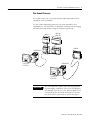
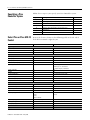
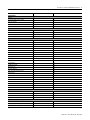
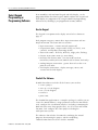
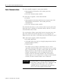
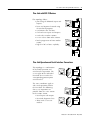
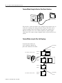
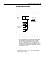
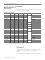
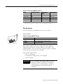
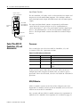
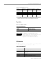
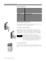
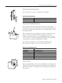
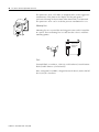
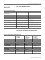
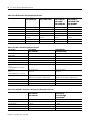
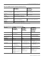
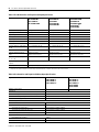
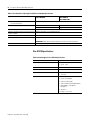
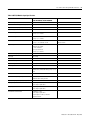
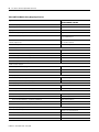
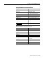
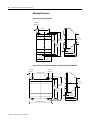
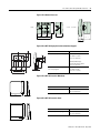
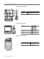
Pico and
Pico GFX-70
Programmable
Controllers
Selection Guide
1760
2
Pico and Pico GFX-70 Programmable Controllers
Publication 1760-SG001F-EN-P - May 2006
Pico and Pico GFX-70 Programmable Controllers
Pico Overview
3
Small, Simple, and Flexible
The Allen-Bradley Pico controller performs simple logic, timing,
counting, and real-time clock operations. For enhanced functionality
and performance, the Pico GFX controller adds the use of a graphic
display while offering advanced programming features like PID
control, a high-speed counter, and Boolean sequences. Splitting the
difference between a timing relay and a low-end programmable
controller, the Pico controllers are ideal for relay replacement
applications where simple control applications such as building,
HVAC, and parking lot lighting, and applications in which cost is a
primary design issue. The Pico controllers were designed with
ease-of-use in mind. All programming and data adjustments can be
done via the on-board keypad and display, or with Allen-Bradley
PicoSoft and PicoSoft Pro configuration software.
Pico Components
The basic Pico components include Pico controllers and Pico
expansion I/O modules. The Pico expansion I/O modules can be
used with Pico EX and Pico GFX-70 controllers to increase your I/O
capacity.
You can add one Pico expansion I/O module for each controller in
your system. Mixing I/O types is also possible by combining an AC
controller with a DC expansion module.
Pico Controllers
Incoming Power
LCD Display
Del
Inputs
Alt
Keypad
Esc
Del
Esc
Write-On
Surface
Ok
Alt
Ok
Pico Expansion I/O Modules
Outputs
Socket for memory module
or PC interface cable
Power/Run LED
Inputs
Write-On
Surfaces
Incoming Power
Status LED
Outputs
Publication 1760-SG001F-EN-P - May 2006
4
Pico and Pico GFX-70 Programmable Controllers
Pico GFX-70 Components and Connections
With its multi-function display, the Pico GFX-70 controller adds more
flexibility and capability to the Pico family of Allen-Bradley
controllers. It displays text, date, time, and even your own custom
bitmaps. These graphics can be used as operator interface, or linked
to control operations to provide real-time feedback. This controller
offers an attractive and practical design with an IP65 display on the
outside of your panel, and the controller and I/O conveniently housed
within the panel. The 70 mm graphic display is backlit for readability.
Even the keypad buttons are illuminated for use in low light
conditions. The controller may also be attached to a DIN rail when the
display unit is not required.
Point-to-Point
Serial Connection
between 2 Processors
Pico-Link
Intraconnect
Display Unit
Front View
Memory Module
Programming Cable
or Serial Connection
Publication 1760-SG001F-EN-P - May 2006
Processor
Unit
Expansion I/O
Pico and Pico GFX-70 Programmable Controllers
5
Pico Remote Processor
The remote processor is used for terminal mode operation of Pico
controllers and I/O modules.
Use the remote mounting processor with Pico controllers, Pico
expansion I/O, and Pico GFX-70 controllers. Perform text messaging
and make data adjustments using the display/keypad unit.
1760-L18...
1760-L20...
1760-L12...
DEL
ESC
1760-LDF...
AT
L
1760-RM-PICO
DEL
AT
L
ESC
OK
OK
Display Unit
Front View
1760-RM-GFX
Display Unit
Front View
IMPORTANT
The 1760-RM-GFX remote processor only provides
text messaging capabilities. To use the full graphics
functionality, you must use the point-to-point serial
connection or the Pico-Link intraconnect between
two Pico GFX-70 processors as shown on page 4.
Publication 1760-SG001F-EN-P - May 2006
6
Pico and Pico GFX-70 Programmable Controllers
Specifying a Pico
Controller System
Follow these steps as you specify your Pico Controller system.
Step
1.
2.
3.
4.
5.
6.
7.
Select Pico or Pico GFX-70
Control
Description
Select Pico or Pico GFX-70 Control
Page
6
Select Keypad Programming or Programming Software
8
Select Communications
10
Select Pico Controllers, I/O and Accessories
14
Select Pico GFX-70 Controllers, I/O, and Accessories
16
Specifications
21
Fill in the Selection Worksheet
33
Review the features shown in the following table to decide which
level of Pico control is right for you.
Pico Control
Pico GFX-70 Control
120/240V ac
24V dc
✔
✔
✔
✔
12V dc
HMI
LCD display
Text display feature
✔
✔
✔
✔
✔
Text display screens, Max
Lines of text per display screen, Max
8
4
255
4
Text length, Max
16 characters
Display languages
Keypad
12
✔
Standard type size: 16 characters
Double type size: 8 characters
7-Segment display: 4 characters
10
✔
Operating Power
Freely definable keys
Graphics display feature
Graphics display capacity, Max
Integrated status LED indicators
5 (31 functions per key), Max
✔
1
24 KB (255 screens and 255 elements per screen, Max)
2
I/O
Embedded I/O, Max.
20
16
I/O count with expansion module, Max
Remote expansion
40
using 1760-RM-PICO
36
using 1760-RM-GFX
I/O count with Pico-Link, Max
Digital Input Types
Digital output types
Analog input types
Analog output types
Real Time Clock
DeviceNet
Publication 1760-SG001F-EN-P - May 2006
120V ac
24V dc
12V dc
24V ac or 24V dc
24V transistor, relay
0...10V
✔
✔
272
120V ac
24V dc
24V dc transistor, relay
0...10V
0...10V
✔
✔
Pico and Pico GFX-70 Programmable Controllers
Pico Control
7
Pico GFX-70 Control
Programming
Keypad
✔
Pre-programmed memory module
Picosoft software
✔
✔
✔
Picosoft pro software
Programming rungs, Max
✔
128
✔
256
Pico-Link
Number of Pico-link stations
8
Pico-link communication rate
Pico-link length, Max
10 KBits/s to 1000 KBits/s
1000 m (3280 ft)
Pico-link data transfer, Max
Function Blocks
32 double words
Timer
Counter
✔
✔
✔
✔
Analog comparator
Operating hours counter
✔
✔
✔
✔
7-Day time switch
Year time switch
✔
✔
✔
✔
Text display
Master reset
✔
✔
✔
✔
Frequency counter
High-speed counter
✔
✔
✔
✔
Comparator
Set cycle time
✔
✔
✔
✔
Arithmetic function
Block functions
✔
✔
Boolean operation
High-speed incremental encoder
✔
✔
PID controller
Signal smoothing filter
✔
✔
GET/PUT Pico-link value
Synchronize clock via Pico-link
✔
✔
Value scaling
Numerical converters
✔
✔
Pulse width modulation (PWM)
Value limitation
✔
✔
Certifications
Degree of protection
CE
IP20
✔
Display: IP65, NEMA 4X, Processor: IP20
✔
UL, CSA
Class I, Division 2 Hazardous Location
✔
✔
✔
✔
Operating Temperature Range
Controller temperature range
-25…55 °C (-13…131 °F)
-25…55 °C (-13…131 °F)
Display temperature range
Storage/transport temperature range
n/a
-40…70 °C (-40…158 °F)
-5…55 °C (23…131 °F)
-40…70 °C (-40…158 °F)
Publication 1760-SG001F-EN-P - May 2006
8
Pico and Pico GFX-70 Programmable Controllers
Select Keypad
Programming or
Programming Software
Pico controllers, with on-board keypad and LCD display, can be
programmed from the front keypad. Models without the keypad and
LCD display are programmed by using PicoSoft Pro programming
software or by installing a pre-programmed memory module.
Use the Keypad
The keypad is an option on the display unit which is shown on
page 17.
Each program rung may contain three input instructions and one
output instruction. The instruction set includes:
• Input instructions - examine-on and examine-off.
• Output instructions - output enable (OTE), set (latch), reset
(unlatch), and flip-flop (alternating on/off).
• Timer instructions - on-delay, off-delay, single pulse, flashing.
• Counter instructions-count up, count down.
• Real-time Clock instructions - turn on or off based on
time-of-day and day-of-week (models with real-time-clock only).
• Analog Compare instructions - greater than or less than a set
point or each other.
• Text Display instructions - display messages, timers, and
counters on the LCD display.
PicoSoft Pro Software
PicoSoft Pro software includes all the features you need to:
• create a project.
• wire up a circuit diagram.
• test a circuit diagram.
• transfer it.
• print it out.
The PicoSoft Pro application is a complete package. It enables you to
create the control software, assign parameters to the function blocks
used, configure the visualization interface (including customizing the
look with your own *.bmp graphic files), use all screens and button
functions, and configure the entire project including the
multi-processor systems.
The software also includes functions for simulating the control
program, documenting the project, and for establishing
communication between the PC and the controller.
Publication 1760-SG001F-EN-P - May 2006
Pico and Pico GFX-70 Programmable Controllers
9
Table 1 Programming Software Selection
Catalog Number
1760-PICOSOFTPRO
1760-CBL-PC02
1760-PICOPRO-PC02
Description
PicoSoft Pro programming software
Programming cable, PC to processor
PicoSoft Pro Software and cable kit (includes 1760-PICOSOFTPRO
and 1760-CBL-PC02)
Software Compatibility
If you are using programming software to program the Pico controller,
be sure that you are using the correct software version.
IMPORTANT
PicoSoft version 6.1 or later must be used to for the
Series B Pico controller. Earlier versions of PicoSoft
software can only be used with Series A Pico
controllers.
Publication 1760-SG001F-EN-P - May 2006
10
Pico and Pico GFX-70 Programmable Controllers
Select Communications
The Pico controller supports 2 connection methods.
• Point-to-point serial interface with remote processor,
1760-RM-PICO
• DeviceNet communications module
The Pico GFX-70 supports 3 connection methods.
• Pico-Link
• Point-to-point serial connection between two processors (also
point-to-point serial interface with remote processor,
1760-RM-GFX)
• DeviceNet communications module
The Pico-Link intraconnect can be used to connect up to 8 processors.
Each processor is considered a Pico-Link station, and they can share
all visualization and I/O data.
The serial interface allows connection between two processors. One
processor could be located for operator access to a keypad and
display to share data with a second processor located behind a panel.
Both connections support 3 modes of operation.
• Run mode/Stop mode
• Card mode (processor starts up using the program stored on the
installed memory module)
• Terminal mode
This allows you to remotely control other devices. This is
especially useful if the other device is located in an inaccessible
place. Terminal mode can also be used to show the menus and
displays of devices that do not have their own display or
keypad. Terminal mode can be used both with the serial
interface and in the Pico-Link network. The serial interface
enables you to access a remote device. If you use the Pico-Link
network, all other network stations can be addressed.
IMPORTANT
Publication 1760-SG001F-EN-P - May 2006
Terminal mode is a separate operating mode like
RUN mode. It only functions when a program is not
running. For this mode to be active, the GFX
controller must be in STOP mode. All connected
devices must also support Terminal mode.
Pico and Pico GFX-70 Programmable Controllers
11
Pico-Link with GFX-70 Devices
This topology allows:
• processing of additional inputs and
outputs.
• faster and improved control using
decentralized programs.
• synchronize date and time.
• read and write inputs and outputs.
• send values to other stations.
• receive values from other stations.
• load a program to or from another
station.
• high level of real-time capability.
GFX-70
GFX-70
GFX-70
GFX-70
Pico-Link Operation and Serial Interface Connections
This topology is a combination
of Pico-Link operation and
serial interface operation. The
access rights of the individual
Pico-Link devices and in the
corresponding point-to-point
serial interface.
GFX-70
GFX-70
The same conditions apply as
with serial operation without
the Pico-Link. The following
data access operations are
possible from the active station
to the remote station.
• Local inputs and outputs
• Pico-Link diagnostics bits
• Write/read accesses to
markers
GFX-70
GFX-70
Publication 1760-SG001F-EN-P - May 2006
12
Pico and Pico GFX-70 Programmable Controllers
Terminal Mode Using the Point-to-Point Serial Interface
TERMIN
AL
Active Station
Remote Station
This interface connection allows the reading of input/output states as
well as the reading and writing of marker ranges. This data can be
used for setpoint entry or for display functions. The stations have
different functions. The active station controls the point-to-point
connection. The remote station responds to the requests of the active
station.
Terminal Mode using the Pico-Link Topology
Terminal mode allows the
active station to control any
processor within the Pico-Link.
First Station on the Pico-Link
Terminating
Resistor
Location 1
Station 1
R 1 - 12
GFX-70
S1-8
TERMIN
A
Location 2
GFX-70
GFX-70
Station 2
Location 3
GFX-70
Station 3
Last Station on the Pico-Link
Location 4
Station 4
Publication 1760-SG001F-EN-P - May 2006
GFX-70
Terminating
Resistor
Pico and Pico GFX-70 Programmable Controllers
13
DeviceNet Communications Module
The Pico DeviceNet module, 1760-DNET, allows you to have a Pico
controller operate as a slave device on the DeviceNet network.
The DeviceNet module connects to the Pico controller like an
expansion I/O module. It can be used with the Pico 18- and 20-point
controllers and the Pico GFX-70 controller. 24V dc power must be
provided to the device.
DeviceNet
Master
Pico Controllers
as Slave Devices
The DeviceNet module is equipped with Network and Module status
LEDs. It uses the following communication profile.
• Predefined master/slave communication settings
– The I/O polling connection is used for the transfer of 3 bytes
of input data (R1 to R16) and 3 bytes of output data (S1 to S8)
between the Pico controller and the DeviceNet master.
– The I/O Change of State/Cyclic connection (acknowledged,
unacknowledged) is used to transfer 2 bytes of diagnostic
data from the Pico controller to the DeviceNet master.
– The explicit connection set-up is used for read/write access to
function relay parameters in the Pico controller. This type of
connection set-up also supports the configuration, diagnostics
and management services.
• DeviceNet Communication adapter profile (device type 12)
• Group 2 server
• UCMM-capable device
• Dynamic set-up of explicit and I/O connections are possible
• Device Heartbeat Message
• Device Shutdown Message
• Offline communication settings
Publication 1760-SG001F-EN-P - May 2006
14
Pico and Pico GFX-70 Programmable Controllers
Select Pico Controllers, I/O Pico Controllers
and Accessories
Select Pico controllers for up to 20 I/O points. Add a Pico expansion
I/O module for up to 40 I/O points.
Table 2 Pico Controllers Selection
Cat. No.
Line Power
Input Voltage
Category
Number of
Inputs (Digital)
Number of
Outputs
Analog
Pico Variation
1760-L12AWA
120/240V ac
120/240V ac
8
4 (relay)
No
1760-L12AWA-NC
120/240V ac
120/240V ac
8
4 (relay)
no real-time clock
1760-L12AWA-ND
120/240V ac
120/240V ac
8
4 (relay)
no display
1760-L18AWA
120/240V ac
120/240V ac
12
6 (relay)
1760-L18AWA-EX
120/240V ac
120/240V ac
12
6 (relay)
I/O expandable
1760-L18AWA-EXND
120/240V ac
120/240V ac
12
6 (relay)
I/O expandable, no display
1760-L12NWN
24V ac
24V ac or 24V dc 8
4 (relay)
1760-L12NWN-ND
24V ac
24V ac or 24V dc 8
4 (relay)
1760-L18NWN-EX
24V ac
24V ac or 24V dc 12
6 (relay)
1760-L18NWN-EXND
24V ac
24V ac or 24V dc 12
6 (relay)
1760-L12DWD
12V dc
12V dc
8(1)
4 (relay)
1760-L12DWD-ND
12V dc
12V dc
8(1)
4 (relay)
1760-L18DWD-EX
12V dc
12V dc
12(1)
6 (relay)
1760-L18DWD-EXND
12V dc
12V dc
12(1)
6 (relay)
1760-L12BBB
24V dc
24V dc
8(1)
4 (transistor)
1760-L12BBB-ND
24V dc
24V dc
8(1)
4 (transistor)
1760-L12BWB
24V dc
24V dc
8(1)
4 (relay)
1760-L12BWB-NC
24V dc
24V dc
(1)
8
4 (relay)
no real-time clock
1760-L12BWB-ND
24V dc
24V dc
8(1)
4 (relay)
no display
1760-L18BWB-EX
24V dc
24V dc
12(1)
6 (relay)
I/O expandable
1760-L18BWB-EXND
24V dc
24V dc
12(1)
6 (relay)
I/O expandable, no display
1760-L20BBB-EX
24V dc
24V dc
12(1)
8 (transistor)
1760-L20BBB-EXND
24V dc
24V dc
12(1)
8 (transistor)
(1)
2 (0...0V dc)
no display
4 (0...10V dc)
I/O expandable
I/O expandable, no display
2 (0...10V dc)
no display
4 (0...10V dc)
I/O expandable
I/O expandable, no display
2 (0...10V dc)
no display
4 (0...10V dc)
I/O expandable
I/O expandable, no display
Two of the digital dc inputs can alternately be used as 0...10V dc analog inputs. These inputs can be used as either digital or analog, not both. For example, you could use
2 analog inputs plus 10 digital inputs on the 1760-L18DWD-EX controller.
Pico Expansion I/O
Depending on which Pico controller you use, expansion I/O modules
can provide up to 40 I/O points when used with expansion I/O
modules.
You can only add one Pico expansion I/O module to each controller.
Publication 1760-SG001F-EN-P - May 2006
Pico and Pico GFX-70 Programmable Controllers
15
Table 3 Pico Expansion I/O Module Selection
Cat. No.
Input Voltage Category
Number of Inputs
(Digital)
Number of Outputs
1760-IA12XOW6I
120 / 240V ac
12
6 (isolated relay)
1760-IB12XOB8
24V dc
12
8 (transistor)
1760-IB12XOW6I
24V dc
12(1)
6 (isolated relay
1760-OW2
n/a
0
2 (relay)
(1)
(1)
Four of the digital dc inputs can alternately be used as 0...10V dc analog inputs. These inputs can be used as
either digital or analog, not both. For example, you could use 4 analog inputs plus 8 digital inputs.
Pico Accessories
This section provides information on various accessories.
Memory Modules
Table 4 Pico Memory Module Selection
1760-MM1 for all 1760-L12xxx
Cat. No.
Description
1760-MM1
Pico 8 K memory module for 12-point controllers
1760-MM2
Pico 16 K memory module for 18-point controllers
1760-MM2B
Pico 32 K memory module
Each memory module can store a single Pico circuit diagram.
Information stored on the memory module is non-volatile. The
memory module can be used to make a backup copy of a program
and/or transfer it to another Pico controller.
Each memory module stores:
• the circuit diagram.
• all parameter settings of the circuit diagram.
• system settings.
IMPORTANT
The 1760-MM2B 32k memory module will not
operate with Series A controllers. In addition,
1760-MM1 and 1760-MM2 memory modules are
READ ONLY when used with the Series B
controllers.
Publication 1760-SG001F-EN-P - May 2006
16
Pico and Pico GFX-70 Programmable Controllers
Digital I7 and I8
Inputs Analog Inputs
I1
I3
I2
I5
I4
I7
I6
Del
Connection
Cable
Esc
Q1
Q2
Q3
I8
Alt
Ok
1760-L12BWB
1760-L12BWB-NC
1760-L12BWB-ND
Q4
Output LEDs
Input/Output Simulator
The DC Simulator, 1760-SIM, can be used to simulate Pico inputs and
outputs to test and troubleshoot programs. The simulator contains
input simulator board, output simulator board, and wall-mount power
supply.
The input simulator board contains 8 maintained push buttons
connected to the 8 inputs of Pico as well as 2 potentiometers
connected to Inputs 7 and 8. The push buttons simulate digital input
devices. The potentiometers can be used to simulate analog input
devices. The output board contains four LEDs that simulate output
devices.
Power Supply Unit
Select Pico GFX-70
Controllers, I/O, and
Accessories
Processors
This section helps you select Pico GFX-70 Controllers, I/O, and
accessories. There are 4 processor versions.
Table 1 Pico GFX-70 Processor Selection
Processor
Line Power
Description
1760-LDF
24V dc
Pico GFX-70 DC processor unit
1760-LDFA
120/240V ac
Pico GFX-70 AC processor unit
1760-LDFC
24V dc
Pico GFX-70 DC processor unit with Pico-Link
terminal
1760-LDFCA
120/240V ac
Pico GFX-70 AC processor unit with Pico-Link
terminal
If your system requires more than 36 I/O, you will need to have
multiple processors using the Pico-Link. You can connect up to 8
processors. To use the Pico-Link, select the 1760-LDFC or 1760-LDFCA
processor.
GFX I/O Modules
GFX I/O modules connect to the back of the GFX processor. Pico
Expansion I/O modules connect to side of controller, and can be used
with Pico or Pico GFX-70 controllers.
You can only add one GFX I/O module and one Pico expansion I/O
module to each controller. Pico expansion I/O is shown on page 14.
Publication 1760-SG001F-EN-P - May 2006
Pico and Pico GFX-70 Programmable Controllers
17
Table 5 Pico GFX I/O Modules Selection
Cat. No.
Input Voltage
Category
Number of Inputs Number of
(Digital)
Outputs
Analog
Capability
1760-IA12XOW4I
120V ac
12
4 (relay)
none
1760-IB12XOW4IF
24V dc
(1)
12
4 (relay)
input
1760-IB12XOW4IOF
24V dc
12(1)
4 (relay)
input and output
1760-IB12XOB4IF
24V dc
12(1)
4 (transistor)
input
1760-IB12XOB4IOF
24V dc
(1)
4 (transistor)
input and output
(1)
12
Four of the digital dc inputs can alternately be used as 0...10V dc analog inputs. These inputs can be used as
either digital or analog, not both. For example, you could use 4 analog inputs plus 8 digital inputs.
Display Units
There are 2 display versions.
Table 6 Display Unit Selection
Cat. No
Description
1760-DUB
Display unit with keypad
1760-DU
Display unit without keypad
TIP
All controllers can be mounted on a panel.
Graphics display units cannot be mounted on a DIN
rail. The Pico GFX-70 processor and other
components can be mounted on a DIN rail.
GFX Accessories
The following table shows a summary of the accessories for Pico GFX
controllers. Detailed descriptions for each item follow.
Table 7 Pico GFX-70 Selection
Cat. No.
Description
1760-CBL-PCO2
Programming cable, PC to processor
1760-PICOSOFTPRO
PicoSoft Pro programming software (see page 8)
1760-PICOPRO-PC02
PicoSoft Pro software and cable kit (includes 1760-PICOSOFTPRO and
1760-CBL-PC02)
1760-MM3
256 K memory module
1606-XLP30E
Power supply
1760-CBL-2M
Point-to-point serial interface cable, 2 m (6.6 ft)
Publication 1760-SG001F-EN-P - May 2006
18
Pico and Pico GFX-70 Programmable Controllers
Table 7 Pico GFX-70 Selection
1760-CBL-5M
Point-to-point serial interface cable, 5 m (16.4 ft)
1760-CBL-INT01
Pico-link cable, 0.3 m (1 ft)
1760-CBL-INT03
Pico-link cable 0.8 m (2.6 ft)
1760-CBL-INT05
Pico-link cable 1.5 m (5 ft)
1760-CBL-INT300
Pico-link cable, non-terminated, 100 m (300 ft)
1760-CONN-RJ45
Connectors for Pico-link cable
1760-TERM1
Network termination resistor
1760-NDM
Membrane protect display
1760-NDC
Cover to protect display
1760-NMF
Mounting feet
1492-N90
Screwdriver
1492-KWC
Wire cutter
GFX Programming Cable (1760-CBL-PC02)
The programming cable is used to transfer data between the PC and
the processor when using PicoSoft Pro Software.
GFX 256K Memory Module (1760-MM3)
Information stored on the memory module is non-volatile. Use the
module to archive, transfer, and copy your circuit diagram. Each
memory module can store one GFX program. It stores the program,
visualization data, and all parameter settings of the circuit diagram.
TIP
Controllers without a keypad and display
automatically transfer the circuit diagram from the
inserted memory card to the Processor when the
power supply is switched on. If the memory card
contains an invalid circuit diagram, GFX will keep
the circuit diagram still present on the device.
Power Supply (1606-XLP30E)
This 24V dc power supply is sized to provide enough power for any
Pico-GFX 70 system. Line power can be 100 to 240V ac or 85 to 375V
dc.
Publication 1760-SG001F-EN-P - May 2006
Pico and Pico GFX-70 Programmable Controllers
19
Point-to-Point Serial Interface Cables
The serial interface cables are available in two lengths.
Table 8 Serial Cable Selection
Cat. No.
Description
1760-CBL-2M
Point-to-point serial interface cable, 2 m (6.6 ft)
1760-CBL-5M
Point-to-point serial interface cable, 5 m (16.4 ft)
Cables for Pico-Link between Processors
The 1760-LDFC and 1760-LDFCA processors have two Pico-Link
terminals. Up to 8 of these processors can be connected together. The
first and last stations in the network must be provided with a 124 Ω
termination resistor.
The 1760-LDFC and 1760-LDFCA processors have two RJ45 sockets.
Socket 1 in the first station is for the termination resistor. For
subsequent stations, socket 1 is used for plugging in the incoming
cable. Socket 2 is used for the outgoing cable or for the termination
resistor on the last physical station on the network.
The cables are available in several lengths, including a long,
non-terminated version that you can cut to fit your needs.
Table 9 Pico-Link Cable Selection
Cat. No.
Description
1760-CBL-INT01
Pico-link cable, 0.3 m (1 ft)
1760-CBL-INT03
Pico-link cable 0.8 m (2.6 ft)
1760-CBL-INT05
Pico-link cable 1.5 m (5 ft)
1760-CBL-INT300
Pico-link cable, non-terminated, 100 m (300 ft)
1760-CONN-RJ45
Connectors for Pico-Link cable
1760-TERM1
Network termination resistor
Protective Covers
For special applications such as in the food industry, the display and
keypad must be protected against dust and liquids. For example, the
protective membrane, 1760-NDM, has been designed specifically for
this purpose.
Publication 1760-SG001F-EN-P - May 2006
20
Pico and Pico GFX-70 Programmable Controllers
The protective cover, 1760-NDC, is designed to be used in aggressive
environments. This protects the display and keypad against
mechanical damage or destruction. Protection to IP65 is maintained.
The protective cover can be sealed to prevent unauthorized access.
Mounting Feet
Mounting feet are required for attaching processors and I/O modules
to a panel. Three mounting feet are sufficient for a device with four
mounting points.
!
CK
CLI
Processor with
mounting feet
installed.
Tools
Terminal Block screwdriver, 1492-N90, with hardened 3 mm diameter
blade (handle from recycled material).
Wire cutting tool, 1492-KWC, designed to attach directly to the shaft of
the 1492-N90 screwdriver.
Publication 1760-SG001F-EN-P - May 2006
Pico and Pico GFX-70 Programmable Controllers
Specifications
21
Pico and Pico GFX-70 Specifications
Table 10 Environmental Specifications
Specification
Pico
Pico GFX-70
Operating temperature (Installed
horizontally/vertically)
-25…55 °C (-13…131 °F)
-25…55 °C, (-13…131 °F)
Display legibility
-25…55 °C (-13…131 °F)
-5…50 °C, (-23…122 °F)
Storage/transport temperature
-40…70 °C (-40…158 °F)
-40…70 °C (-40…158 °F)
Relative humidity (IEC 60068-2-30)
5 to 95% non-condensing
5 to 95% non-condensing
Pollution degree
2
Power supply unit/CPU; inputs/outputs: 2
Display/keypad: 3
Degree of protection
(EN50178, IEC 60529, VBG4)
IP20
Processor Unit; I/O :IP20
Display Unit: IP65
Vibration (IEC 60068-2-6)
Constant amplitude 0.15 mm: 10 … 57 Hz
Constant acceleration 2g: 57 … 150 Hz
Constant amplitude 0.15 mm: 10 … 57 Hz
Constant acceleration 2g: 57 … 150 Hz
Shock (IEC 60068-2-27)
18 shocks, semi-sinusoidal 15g/11 ms
18 shocks, semi-sinusoidal 15g/11 ms
Agency Certification
UL, CSA, CE
Class I, Division 2 Hazardous Location
UL, CSA, CE
Pico Controllers and Pico Expansion I/O Specifications
Table 11 Pico AC Controllers Power Supply Specifications
Incoming Power
1760-L12AWA
1760-L12AWA-NC
1760-L12AWA-ND
1760-L18AWA
1760-L18AWA-EX
1760-L18AWA-EXND
1760-IA12XOW6I
1760-L12NWN
1760-L12NWN-ND
1760-L18NWN-EX
1760-L18NWN-EXND
Rated value (sinusoidal)
110…240V ac +10/-15%
100…240V ac +10/-15%
24V ac, +10 / -15%
Range
90…264V ac
85…264V ac
20.4…26.4V ac
Frequency, rated value, tolerance
50/60 Hz, ±5%
50/60 Hz, ±5%
50/60 Hz, ±5%
Nominal 40 mA
Nominal 70 mA
–
Line Current
at 115/120V ac 60 Hz
at 230/240V ac 50 Hz
Nominal 20 mA
Nominal 35 mA
–
at 24V ac 50/60 Hz
–
–
Nominal 200 mA (1760-L12)
Nominal 300 mA ((1760-L18)
20 ms, EN 61131-2
20 ms, EN 61131-2
20 ms, EN 61131-2
at 115/120V ac
Nominal 5 VA
Nominal 10 VA
–
at 230/240V ac
Nominal 5 VA
Nominal 10 VA
–
at 24V ac
–
–
Nominal 5 VA (1760-L12)
Nominal 7 VA (1760-L18)
Voltage dips
Power Consumption
Publication 1760-SG001F-EN-P - May 2006
22
Pico and Pico GFX-70 Programmable Controllers
Table 12 Pico DC Controllers Power Supply Specifications
Incoming Power
1760-L12DWD
1760-L12DWD-ND
1760-L18DWD-EX
1760-L18DWD-EXND
1760-L12BBB
1760-L12BBB-ND
1760-L12BWB
1760-L12BWB-NC
1760-L12BWB-ND
1760-L18BWB-EX
1760-L20BBB-EX
1760-L20BBB-EXND
1760-IB12XOW6I
1760-IB12XOB8
12V dc, +30%, -15%
12V dc, +30%, -15%
24V dc, +20%, -15%
24V dc, +20%, -15%
Rated voltage
Rated value
Range
10.2…15.6V dc
10.2…15.6V dc
20.4…28.8V dc
20.4…28.8V dc
Residual ripple
≤5%
≤5%
≤5%
≤5%
Input current
Nominal 140 mA
at 12V dc
Nominal 200 mA
at 12V dc
Nominal 80 mA
at 24V dc
Nominal 140 mA
at 24V dc
Voltage dips
10 ms, EN 61131-2
10 ms, EN 61131-2
10 ms, EN 61131-2
10 ms, EN 61131-2
Power dissipation at 24V dc
Nominal 2W
Nominal 3.5W
Nominal 2W
Nominal 3.5W
Table 13 Pico 24V ac Controllers Input Specifications
Specification
1760-L12NWN
1760-L12NWN-ND
1760-L18NWN-EX
1760-L18NWN-EXND
Number of digital inputs
8
12
Rated voltage
24V ac
24V ac
Off-state voltage
0…6V ac
0…6V ac
On-state voltage
14…26.4V ac
14…26.4V ac
Rated frequency
50/60 Hz
50/60 Hz
Input current
I1 to I6
(1760-L18NWN-xx also I9 to I10)
4 mA at 24V ac 50 Hz
4 mA at 24V ac 50 Hz
Input current
I7, I8
(1760-L18NWN-xx also I11 and I12)
2 mA at 24V ac 50 Hz,
2 mA at 24V
2 mA at 24V ac 50 Hz,
2 mA at 24V
Signal delay
Debounce On: 80 ms (50 Hz), 66.66 ms (60 Hz)
Debounce Off: 20 ms (50 Hz), 16.66 ms (60 Hz)
Debounce On: 80 ms (50 Hz), 66.66 ms (60 Hz)
Debounce Off: 20 ms (50 Hz), 16.66 ms (60 Hz)
Number of analog inputs
2
4
Input Type
dc voltage
dc voltage
Signal Range
0…10V dc
0…10V dc
Table 14 Pico 120/240V ac Controllers and Expansion I/O Input Specifications
Specification
1760-L12AWA
1760-L12AWA-NC
1760-L12AWA-ND
1760-L18AWA
1760-L18AWA-EX
1760-L18AWA-EXND
1760-IA12XOW6I(1)
Number of digital inputs
8
12
Rated voltage (sinusoidal)
120/240V ac
120/240V ac
Off-state voltage
0…40V ac
0…40V ac
On-state voltage
79…264V ac
79…264V ac
Rated frequency
50/60 Hz
50/60 Hz
Publication 1760-SG001F-EN-P - May 2006
Pico and Pico GFX-70 Programmable Controllers
23
Table 14 Pico 120/240V ac Controllers and Expansion I/O Input Specifications
Specification
1760-L12AWA
1760-L12AWA-NC
1760-L12AWA-ND
1760-L18AWA
1760-L18AWA-EX
1760-L18AWA-EXND
1760-IA12XOW6I(1)
Input current
R1 to R12, I1 to I6 (1760-L18AWA-xx
also I9 to I12)
0.5 mA at 230V ac 50 Hz,
0.25 mA at 115V ac 60 Hz
0.5 mA at 230V ac 50 Hz
0.25 mA at 115V ac 60 Hz
Input current
I7, I8
6 mA at 230V ac 50 Hz,
4 mA at 115V ac 60 Hz
6 mA at 230V ac 50 Hz,
4 mA at 115V ac 60 Hz
Signal delay
I1 to I6 and I9 to I12
from 0 to 1 and from 1 to 0
Debounce On: 80 ms (50 Hz), 66.66 ms (60 Hz)
Debounce Off: 20 ms (50 Hz), 16.66 ms (60 Hz)
Signal delay
Delay time I7, I8
from 1 to 0
Debounce On: 160 ms (50 Hz), 150 ms (60 Hz)
Debounce Off: 100 ms (50 Hz/60 Hz)
Signal delay
I7, I8 from 0 to 1
Debounce On: 80 ms (50 Hz), 66.66 ms (60 Hz)
Debounce Off: 20 ms (50 Hz), 16.66 ms (60 Hz)
(1)
Debounce On: 80 ms (50 Hz), 66.66 ms (60 Hz)
Debounce Off: 20 ms (50 Hz), 16.66 ms (60 Hz)
Delay times for expansion modules are circuit delays only. Additional time is needed to transfer the status to the controller.
Table 15 Pico DC Controllers and Expansion I/O Input Specifications
Specification
1760-L12DWD
1760-L12DWD-ND
1760-L18DWD-EX
1760-L18DWD-EXND
1760-L12BBB
1760-L12BBB-ND
1760-L12BWB
1760-L12BWB-NC
1760-L12BWB-ND
1760-L18BWB-EX
1760-L18BWB-EXND
1760-L20BBB-EX
1760-L20BBB-EXND
1760-IB12XOB8(1)
1760-IB12XOW6I
Number of digital inputs
8 (1760-L12DWD-xx)
12 (1760-L18DWD-xx)
8
12
Inputs usable as analog inputs
2 inputs (I7 and I8),
Inputs usable as high-speed
inputs (I1, I2, I3, I4)
4
4
4 (1760-L18xxx and 1760-L20xxx)
Rated Voltage
12V dc
24V dc
24V dc
Off-state Voltage
4.0V dc I1 to I8
< 5.0V dc
< 5.0V dc (I1 to I12, R1 to R12)
On-state Voltage
8V dc I1 to I8
4 inputs (I7, I8, I11, I12) for
1760-L18xxx and 1760-L20xxx
• 15…28.8V dc (I1 to I6)
• 8…28.8V dc (I7, I8)
On-state Current
• 3.3 mA at 12V dc (I1 to I6)
(and I9 to I12 for
1760-L18DWD-xx)
• 3.3 mA at 24V dc (I1 to I6)
• 2.2 mA at 24V dc (I7, I8)
• 1.1 mA at 12V dc (I7, I8)
• 15…28.8V dc (I1 to I6, I9 to I12,
R1 to R12)
• 8…28.8V dc (I7, I8)
• 3.3 mA at 24V dc (I1 to I6, I9 to
I12, R1 to R12)
• 2.2 mA at 24V dc (I7, I8)
Signal delay, 0 to 1
Debounce On: 20 ms
Nominal 0.3 ms
Debounce On: 20 ms
Debounce Off: Nominal 0.25 ms
Debounce On: 20 ms
Debounce Off: Nominal 0.25 ms
Signal delay, 1 to 0
Debounce On: 20 ms
Debounce Off:
Nominal 0.3 ms (I1 to I6 and I9 to I10
1760-L18xxx)
Nominal 0.35 ms (I7, I8 and I11 to I12
1760-L18xxx)
Debounce On: 20 ms
Debounce Off:
Nominal 0.4 ms (I1 to I6)
Nominal 0.2 ms (I7, I8)
Debounce On: 20 ms
Debounce Off:
Nominal 0.4 ms (I1 to I6)
Nominal 0.2 ms (I7, I8)
Publication 1760-SG001F-EN-P - May 2006
24
Pico and Pico GFX-70 Programmable Controllers
Table 15 Pico DC Controllers and Expansion I/O Input Specifications
Specification
1760-L12DWD
1760-L12DWD-ND
1760-L18DWD-EX
1760-L18DWD-EXND
1760-L12BBB
1760-L12BBB-ND
1760-L12BWB
1760-L12BWB-NC
1760-L12BWB-ND
1760-L18BWB-EX
1760-L18BWB-EXND
1760-L20BBB-EX
1760-L20BBB-EXND
1760-IB12XOB8(1)
1760-IB12XOW6I
Number of analog inputs
2 (4 inputs 1760-L18DWD-xx)
2
4
Input Type
dc voltage
dc voltage
dc voltage
Signal Range
0…10V dc
0…10V dc
0…10V dc
Analog Resolution
0.1V
0.1V
0.1V
Input Impedance
11.2K Ω
11.2K Ω
11.2K Ω
±3% of actual value
Accuracy of
Accuracy, Two Pico Devices
±3% of actual value
±3% of actual value
Accuracy, Within a Single Device ±2% of actual value ±0.12V
(I7, I8)
±2% of actual value ±0.12V
±2% of actual value ±0.12V
Input Current
< 1 mA
< 1 mA
< 1 mA
Analog to Digital Conversion
Time
Debounce On: 20 ms
Debounce Off: every cycle
Debounce On: 20 ms
Debounce Off: every cycle
Debounce On: 20 ms
Debounce Off: every cycle
Number of high-speed inputs
(I1, I2, I3, I4)
4
4
4 (1760-L18xxx and 1760-L20xxx)
High-speed up and down
counters
Frequency: < 1 kHz, Pulse shape: square wave
Frequency counters
Frequency: < 1 kHz, Pulse shape: square wave
(1)
Delay times for expansion modules are circuit delays only. Additional time is needed to transfer the status to the controller.
Table 16 Pico Controllers and Expansion I/O Relay Output Specifications
Specification
1760-L12AWA-xx
1760-L12BWB-xx
1760-L12DWD-xx
1760-L12NWN-xx
1760-L18AWA-xx
1760-L18BWB-xx
1760-L18DWD-xx
1760-L18NWN-xx
1760-IA12XOW6I
1760-IB12XOW6I
Number of relay outputs
4
6
In Groups of
1
Connection of Outputs in Parallel to Increase the Output
Not permissible
Protection for an Output Relay
Miniature circuit-breaker B16 or 8 A fuse (slow)
Isolation to Power Supply and Inputs
300V ac reinforced insulation
Contacts Relays
Conventional Thermal Current
8 A (10 A UL)
Recommended for Load
> 500 mA, 12V ac/dc
Short-Circuit Resistance COS 1
16 A characteristic B (B16) at 600 A
Short-Circuit Resistance COS 0.5 to 0.7
16 A characteristic B (B16) at 900 A
Rated Impulse Withstand Voltage Uimp Contact/Coil
6 KV
Rated Insulation Voltage Ui
Rated Operational Voltage Ue
250V ac
Isolation to EN 50178 Between Coil and Contact
300V ac reinforced insulation
Publication 1760-SG001F-EN-P - May 2006
Pico and Pico GFX-70 Programmable Controllers
25
Table 16 Pico Controllers and Expansion I/O Relay Output Specifications
Specification
1760-L12AWA-xx
1760-L12BWB-xx
1760-L12DWD-xx
1760-L12NWN-xx
Isolation to EN 50178 Between Two Contacts
1760-L18AWA-xx
1760-L18BWB-xx
1760-L18DWD-xx
1760-L18NWN-xx
1760-IA12XOW6I
1760-IB12XOW6I
300V ac reinforced insulation
Making Capacity
AC-15 COS φ = 0.4, 250V ac, 3A (600 Ops/h)
300,000 switching operations
DC-13 L/R ≤150 ms, 24V dc, 1A (500 Ops/h)
200,000 switching operations
Breaking Capacity
AC-15 COS φ = 0.7 250V ac, 3 A (600 Ops/h)
300,000 switching operations
DC-13 L/R ≤150 ms 24V DC, 1 A (500 Ops/h)
200,000 switching operations
Filament Lamp Load
1000 W at 230/240V ac/25,000 operations
500 W at 115/120V ac/25,000 operations
Fluorescent Tube with Ballast
10 x 58 W at 230/240V ac/25,000 operations
Conventional Fluorescent Tube, Compensated
1 x 58 W at 230/240V ac/25,000 operations
Fluorescent Tube, Uncompensated
10 x 58 W at 230/240V ac/25,000 operations
Relay Operating Frequency
Mechanical Switching Operations
10 million (107)
Mechanical Switching Frequency
10 Hz
Resistive Lamp Load
2 Hz
Inductive Load
0.5 Hz
Table 17 Pico Controllers and Expansion I/O Transistor Output Specifications
Specification
1760-L12BBB
1760-L12BBB-ND
1760-IB12XOB8
1760-L20BBB-EX
1760-L20BBB-EXND
Number of transistor outputs
4
8
Rated Voltage
24V dc
Voltage Range
20.4...28.8V dc
Residual Ripple
≤5%
Supply Current
Outputs Off
18 mA nominal, 32 mA Max
Outputs On
24 mA nominal, 44 mA Max
Reverse Polarity Protection
Yes
IMPORTANT: If voltage is applied to the outputs when the polarity of the power supply is
reversed, this will result in a short circuit.
Isolation from Power Supply and Input Terminals
500V dc
Rated Current
0.5 A dc Max
Lamp Load
5W
Off State Leakage Current
< 0.1 mA per channel
Maximum Output Voltage Drop
1V dc
Short Circuit Protection
Yes, thermal (detected via diagnostics input I16, I15; R15, R16)
Publication 1760-SG001F-EN-P - May 2006
26
Pico and Pico GFX-70 Programmable Controllers
Table 17 Pico Controllers and Expansion I/O Transistor Output Specifications
Specification
1760-L12BBB
1760-L12BBB-ND
1760-IB12XOB8
1760-L20BBB-EX
1760-L20BBB-EXND
Short Circuit Tripping Current, I
for Load ≤10 milli-ohm
0.7 A ≤ I ≤ 2 A (depending on the number of active channels and their load)
Short Circuit Current
8 A total Max
16 A total Max
16 A peak
32 A peak
Thermal Cutout
Yes
Maximum Switching Frequency with Constant Resistive 40,000 Hz (depending on circuit diagram and load)
Load RL < 100 kΩ
Number of Outputs
4 Max
Total Maximum Current
2.0 A
IMPORTANT: Outputs must be actuated simultaneously and for the same time duration.
Status Display of the Outputs
LCD display (if provided)
Pico GFX-70 Specifications
Table 18 Power Supply for Pico GFX-70 Specifications
Specification
Input Voltage
1606-XLP30E
• AC: 100…240V, 47…63 Hz
• DC: 85…375V
Output Power
30 W
Output Voltage
24…28V dc
Rated Output Current
• 1.3 A at 24.5V
• 1 A at 28V
Approvals
• CE
• C-UL-US Listed (UL508)
• C-UR-US Listed (UL1950)
• Safety Standards IEC/EN 60950 EN50178
• EMC: EN50081-1, EN61000-6-2,
EN61000-3-2
• NEC Class 2
• FM Class 1 Div. 2 (T3A)
Publication 1760-SG001F-EN-P - May 2006
Pico and Pico GFX-70 Programmable Controllers
27
Table 19 GFX I/O Modules Input Specifications
Specification
1760-IB12XOW4IF, 1760-IB12XOW4IOF
1760-IB12XOB4IF, 1760-IB12XOB4IOF
1760-IA12XOW4I
Number of digital inputs
12
12
Inputs usable as analog inputs (I7, I8, I11, I12)
4
0
Inputs usable as high-speed inputs (I1, I2, I3, I4)
4
0
Rated voltage
24V dc
120/240V ac
Off-state voltage
I1 to I6 and I9 to I10: < 5V dc
I7, I8, I11, I12: < 8V dc
0…40V ac
On-state voltage
I1 to I6 and I9 to I10: > 15V dc
I7, I8, I11, I12: > 8V dc
79…264V ac
On-state current
I1 to I6, I9 to I10 at 24V dc: 3.3 mA
I7, I8, I11, I12 at 24V dc: 2.2 mA
115V ac: 0.2 mA
230V ac: 0.5 mA
Signal delay
Debounce On: 20 ms
Debounce Off, typical:
I1 to I4s: 0.025 ms
I5, I6, I9, I10: 0.25 ms
I7, I8, I11, I12: 0.15 ms
–
Number of analog inputs (I7, I8, I11, I12)
4
0
Input type
DC voltage
–
Signal range
0…10V dc
–
Resolution analog
0.01V
–
Resolution digital
10-bit (0…1023 counts)
–
Input impedance
11.2K Ω
–
Accuracy
Two GFX devices, from actual value: ±3%
Within a unit, from actual value, (I7, I8, I11, I12):
±2%
–
Input current
< 1 mA
–
Conversion time, analog to digital
Debounce On: 20 ms
Debounce OFF: each cycle time
–
Number of high-speed inputs (I1, I2, I3, I4)
4
0
High-speed up and down counters
Frequency: < 3 kHz
Pulse shape: square wave
–
Frequency counters
Frequency: < 3 kHz
Pulse shape: square wave
–
Incremental counter encoder
Frequency: < 3 kHz
Pulse shape: square wave
Counter inputs I1 and I2, I3 and I4: 2
Signal offset: 90°
–
Publication 1760-SG001F-EN-P - May 2006
28
Pico and Pico GFX-70 Programmable Controllers
Table 20 GFX I/O Modules Relay Output Specifications
Specification
1760-IA12XOW4I, 1760-IB12XOW4IF
1760-IB12XOW4IOF, 1760-OW2
Number of relay outputs
4 (2 for the 1760-OW2)
Type of outputs
Relays
In groups of
1
Connection of outputs in parallel to increase the output
Not permissible
Protection for an output relay
Miniature circuit-breaker B16: 16 A
or fuse (slow-blow): 8 A
Potential isolation to mains power supply, input, PC interface, memory module, Pico-Link
network, expansion I/O
Safe isolation: 300V ac
Basic insulation: 600V ac
Mechanical life span
10 x 106 switch operations
Contacts relays
Conventional thermal current, (UL)
8 A, (10 A)
Recommended for load at 12V ac/dc
> 500 mA
Protected against short-circuit cos ϕ = 1, 16 A characteristic B (B16) at
600 A
Protected against short-circuit cos ϕ = 0.5 to 0.7, 16 A characteristic B (B16) at
900 A
Rated impulse withstand voltage Uimp contact coil
6 kV
Rated insulation voltage Ui
Rated operational voltage Ue
250V ac
Safe isolation to EN 50178 between coil and contact
300V ac
Safe isolation to EN 50178 between two contacts
300V ac
Making capacity, IEC 60947
AC-15 250V ac, 3 A (600 Ops/h)
300,000 switch operations
DC-13 L/R ≤150 ms 24V dc, 1 A (500 Ops/h)
200,000 switch operations
Breaking capacity, IEC 60947
AC-15 250V ac, 3 A (600 Ops/h)
300,000 switch operations
DC-13 L/R ≤150 ms 24V dc, 1 A (500 Ops/h)
200,000 switch operations
Filament lamp load
1000 W at 230/240V ac
25,000 switch operations
500 W at 115/120V ac
25,000 switch operations
Fluorescent tube with ballast, 10 x 58 W at 230/240V ac
25,000 switch operations
Conventional fluorescent tube, compensated, 1 x 58 W at 230/240V ac
25,000 switch operations
Conventional fluorescent tube, uncompensated, 10 x 58 W at 230/240V ac
25,000 switch operations
Operating frequency, relays
Mechanical switch operations
10 million (107) switch operations
Mechanical switching frequency
10 Hz
Resistive lamp load
2 Hz
Inductive load
0.5 Hz
Publication 1760-SG001F-EN-P - May 2006
Pico and Pico GFX-70 Programmable Controllers
29
Table 21 GFX I/O Modules Transistor Output Specifications
Specification
1760-IB12XOB4IF, 1760-IB12XOB4IOF
Transistor Outputs
4
Rated voltage
24V dc (20.4V dc…28.8V dc)
Supply current
On 0 state: 18 mA (typical), 32 mA (Max)
On 1 state: 24 mA (typical), 44 mA (Max)
Rated current at state 1, maximum
0.5 A
Residual current at state “0” per channel
< 0.1 mA
Short-circuit protection
Thermal (Q1 to Q4)
Yes
(evaluation with diagnostics inputs I16, I15)
Max total short-circuit current
8A
Peak short-circuit current
16 A
Thermal cutout
Yes
Total max current
2A
IMPORTANT
Outputs must be actuated simultaneously and for
the same time duration.
Table 22 GFX I/O Modules Analog Output Specifications
Specification
1760-IB12XOW4IOF, 1760-IB12XOB4IOF
Analog Outputs
1
Output type
DC voltage
Signal range
0…10V dc
Output current max
10 mA
Load resistor
1k Ω
Short-circuit and overload proof
Yes
Resolution analog
0.01V dc
Resolution digital
10-bit
0…1023 counts
Transient recovery time
100 µs
Accuracy (-25…55 °C), related to the range
2%
Accuracy (25 °C), related to the range
1%
Conversion time
Each CPU cycle
Publication 1760-SG001F-EN-P - May 2006
30
Pico and Pico GFX-70 Programmable Controllers
Mounting Dimensions
Figure 1 Pico 12-Point Controller
10.75 mm
(0.423 in.)
50 mm
(1.97 in.)
90 mm
(3.54 in.)
45 mm
(1.77 in.)
110 mm
(4.33 in.)
102 mm
(4.02 in.)
4.5 mm (0.177 in.)
47.5 mm (1.87 in.)
56.5 mm (2.22 in.)
58 mm (2.28 in.)
M4
35.75 mm
(1.41 in.)
71.5 mm
(2.81 in.)
Figure 2 Pico 18- and 20-Point Controllers and Pico Expansion I/O Modules
16.25 mm
(0.640 in.)
16.25 mm
(0.640 in.)
75 mm (2.96 in.)
M4
45 mm
(1.77 in.)
110 mm
90 mm
(4.33 in.)
(3.54 in.)
102 mm
(4.02 in.)
4.5 mm (0.177 in.)
47.5 mm (1.87 in.)
56.5 mm (2.22 in.)
58 mm (2.28 in.)
107.5 mm (4.23 in.)
Publication 1760-SG001F-EN-P - May 2006
Pico and Pico GFX-70 Programmable Controllers
31
2.28"
Figure 3 Pico Remote Processor
1760-DU… and 176-RM…
58
176-RM…
22.5
0.89"
30 1.18"
75
22.5
0.89"
36.2
1.43"
20.5
0.81"
2.95"
43.2
1.7"
27.5
1.08"
Figure 4 Pico GFX-70 Display Unit (with and without keypad)
22.3
30
86.5
32
17
Specification
1760-DU and 1760-DUB
Front dimensions (W x H x D), Approx. 1760-DUB (with keys):
86.5 x 86.5 x 21.5 mm
(3.41 x 3.41 x 0.85 in.)
30
28.25
20
28.25
62
13.7
Total dimensions with fixing shaft
(W x H x D), Approx.
86.5
1760-DU (without keys):
86.5 mm x 86.5 mm x 20 mm
(3.41 x 3.41 x 0.79 in.)
With keys:
86.5 x 86.5 x 43 mm
(3.41 x 3.41 x 1.69 in.)
Figure 5 Pico GFX-70 Protective Membrane
88.5
Specification
Dimensions (W x H x D), Approx.
1760-NDM
88.5 x 88.5 x 25 mm
(3.46 x 3.46 x 0.98 in.)
22.5
88.5
Figure 6 Pico GFX-70 Protective Cover
95
Specification
Dimensions (W x H x D), Approx.
86.5
1760-NDC
86.5 x 95 x 25 mm
(3.41 x 3.41 x 0.98 in.)
25
Publication 1760-SG001F-EN-P - May 2006
32
Pico and Pico GFX-70 Programmable Controllers
Figure 7 Pico GFX-70 Processor Unit
90
Specification
1760-LDF, 1760-LDFA, 1760-LDFC, 1760-LDFCA
Dimensions (W x H x D), 107.5 x 90 x 30 mm
Approx.
(4.23 x 3.54 x 1.18 in.)
38.75
30
16.25
75
38.75
4.5
29.5
16.25
107.5
Figure 8 Pico GFX-70 I/O Modules
90
Specification
88.1
19
25
Dimensions when fitted (W x H x D),
Approx.
Dimensions when removed (W x H x D),
Approx.
1760-IA12XOW4I
1760-IB12XOW4IF
1760-IB12XOW4IOF
1760-IB12XOB4IF
1760-IB12XOB4IOF
88.1 x 90 x 25 mm
(3.5 x 3.54 x 0.98 in.)
88.1 x 90 x 44 mm
(3.5 x 3.54 x 1.73 in.)
Figure 9 Pico GFX-70 Power Supply
Specification
Dimensions (W x H x D), Approx.
H
D
W
Publication 1760-SG001F-EN-P - May 2006
1606-XLP30E
45 x 75 x 91 mm
(1.77 x 2.95 x 3.58 in.)
Pico and Pico GFX-70 Programmable Controllers
33
Fill in the Selection
Worksheet
Catalog Number
Description
Programming Software and Cable
PicoSoft Pro Programming Software
1760-PICOSOFTPRO(1)
1760-CBL-PM02
1760-CBL-PC02
1760-PICOPRO-PC02
Communications Module
1760-DNET
Pico Controllers
1760-L12AWA
1760-L12AWA-NC
1760-L12AWA-ND
1760-L12BBB
1760-L12BBB-ND
1760-L12BWB
1760-L12BWB-NC
1760-L12BWB-ND
1760-L12DWD
1760-L12DWD-ND
1760-L12NWN
1760-L12NWN-ND
1760-L18AWA-EX
1760-L18AWA-EXND
1760-L18BWB-EX
1760-L18BWB-EXND
1760-L18DWD-EX
1760-L18DWD-EXND
1760-L18NWN-EX
1760-L18NWN-EXND
1760-L20BBB-EX
1760-L20BBB-EXND
Pico Expansion I/O Modules
1760-IA12XOW6I
1760-IB12XOB8
1760-IB12XOW6I
1760-OW2
1760-RPLCONN
Pico GFX-70 Processor Units
1760-LDF
1760-LDFA
1760-LDFC
1760-LDFCA
Pico Remote Processor Units
1760-RM-PICO
Pieces per
Package
Quantity Selected
1
Programming Cable, PC to Pico Processor
Programming Cable, PC to Pico GFX Processor
PicoSoft Pro Software and Pico GFX Cable Kit
1
1
Pico DeviceNet Module
1
Pico 12-Point AC Controller
Pico 12-Point AC Controller without Real-Time Clock
Pico 12-Point AC Controller without Display
Pico 12-Point DC Controller
Pico 12-Point DC Controller without Display
Pico 12-Point DC Controller
Pico 12-Point DC Controller without Real-Time Clock
Pico 12-Point DC Controller without Display
Pico 12-Point AC Controller
Pico 12-Point AC Controller without Display
Pico 12-Point AC Controller
Pico 12-Point AC Controller without Display
Pico 18-Point AC Controller I/O Expandable
Pico 18-Point AC Controller I/O Expandable without Display
Pico 18-Point DC Controller I/O Expandable
Pico 18-Point DC Controller I/O Expandable without Display
Pico 18-Point DC Controller I/O Expandable
Pico 18-Point DC Controller I/O Expandable without Display
Pico 18-Point AC Controller I/O Expandable
Pico 18-Point AC Controller I/O Expandable without Display
Pico 20-Point DC Controller I/O Expandable
Pico 20-Point DC Controller I/O Expandable without Display
1
1
1
1
1
1
1
1
1
1
1
1
1
1
1
1
1
1
1
1
1
1
(12) 120/240V ac inputs, (6) isolated relay outputs
(12) 24V dc inputs, (8) transistor outputs
(12) 24V dc inputs, (6) isolated relay outputs
(2) relay outputs
Expansion Module Connector - included with expansion module. Catalog
number listed is replacement part.
1
1
1
1
1
Pico GFX-70 DC Processor Unit
Pico GFX-70 AC Processor Unit
Pico GFX-70 DC Processor Unit with Pico-Link Terminal
Pico GFX-70 AC Processor Unit with Pico-Link Terminal
1
1
1
1
Pico Remote Processor Unit
1
Publication 1760-SG001F-EN-P - May 2006
34
Pico and Pico GFX-70 Programmable Controllers
Catalog Number
Description
1760-RM-GFX
Pico GFX-70 Remote Processor Unit
Pico GFX-70 I/O Modules
1760-IA12XOW4I
(12) 120V ac inputs, (4) relay outputs
1760-IB12XOW4IF
(12) 24V dc inputs, (4) relay outputs, analog input
1760-IB12XOW4IOF
(12) 24V dc inputs, (4) relay outputs, analog input and output
1760-IB12XOB4IF
(12) 24V dc inputs, (4) transistor outputs, analog input
1760-IB12XOB4IOF
(12) 24V dc inputs, (4) transistor outputs, analog input and output
Display Units
1760-DUB
Display Unit with Push buttons
1760-DU
Display Unit without Push buttons
Memory Module
1760-MM1
Pico 8 K Memory Module for 12-Point Controllers
1760-MM2
Pico 16 K Memory Module for 18-Point Controllers
1760-MM2B
Pico 32 K Memory Module
1760-MM3
Pico GFX-70 256 K Memory Module
Power Supply
1606-XLP30E
DC Power Supply
Point-to-Point Serial Interface Cables
1760-CBL-2M
Point-to-Point Serial Interface Cable, 2 m (6.6 ft)
1760-CBL-5M
Point-to-Point Serial Interface Cable, 5 m (16.4 ft)
Cables for Pico-Link between Processors
1760-CBL-INT01
Pico-Link Cable, 0.3 m (1 ft)
1760-CBL-INT03
Pico-Link Cable 0.8 m (2.6 ft)
1760-CBL-INT05
Pico-Link Cable 1.5 m (5 ft)
1760-CBL-INT300
Pico-Link Cable, non-terminated, 100 m (300 ft)
1760-CONN-RJ45
Connectors for Pico-Link Cable
1760-TERM1
Network Termination Resistor
Protective Covers
1760-NDM
Membrane Protect Display
1760-NDC
Cover Protect Display
Mounting Feet
1760-NMF
Mounting Feet (for panel mounting processors and I/O modules)
Tools
1492-N90
Screwdriver
1492-KWC
Wire Cutter
Input Simulator
1760-SIM
Input Simulator for 12 I/O DC Pico Controller
Pieces per
Package
1
Quantity Selected
1
1
1
1
1
1
1
1
1
1
1
1
1
1
5
3
2
1
2
2
1
1
8
5
1
1
(1)
PicoSoft software version 6.1 or later must be used for the Series B Pico controller. Earlier versions of PicoSoft software can only be used with Series A Pico controllers.
Publication 1760-SG001F-EN-P - May 2006
Pico and Pico GFX-70 Programmable Controllers
35
Publication 1760-SG001F-EN-P - May 2006
Rockwell Automation Support
Rockwell Automation provides technical information on the Web to assist you in using its products. At
http://support.rockwellautomation.com, you can find technical manuals, a knowledge base of FAQs, technical and
application notes, sample code and links to software service packs, and a MySupport feature that you can customize
to make the best use of these tools.
For an additional level of technical phone support for installation, configuration, and troubleshooting, we offer
TechConnect Support programs. For more information, contact your local distributor or Rockwell Automation
representative, or visit http://support.rockwellautomation.com.
Installation Assistance
If you experience a problem with a hardware module within the first 24 hours of installation, please review the
information that's contained in this manual. You can also contact a special Customer Support number for initial help
in getting your module up and running.
United States
1.440.646.3223
Monday – Friday, 8am – 5pm EST
Outside United
States
Please contact your local Rockwell Automation representative for any
technical support issues.
New Product Satisfaction Return
Rockwell tests all of its products to ensure that they are fully operational when shipped from the manufacturing
facility. However, if your product is not functioning, it may need to be returned.
United States
Contact your distributor. You must provide a Customer Support case
number (see phone number above to obtain one) to your distributor in
order to complete the return process.
Publication 1760-SG001F-EN-P - May 2006 36
Supersedes Publication 1760-SG001E-EN-P - January 2006
Copyright © 2006 Rockwell Automation, Inc. All rights reserved. Printed in the U.S.A.