1
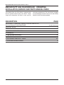
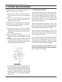
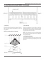
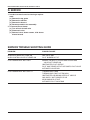
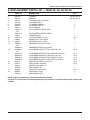
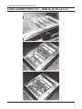
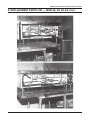
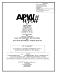
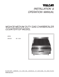
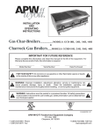
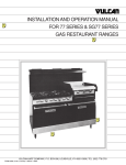
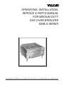
OPERATING, INSTALLATION,
SERVICE & PARTS MANUAL
FOR MEDIUM DUTY
GAS CHAR BROILERS
MGB-A SERIES
VULCAN-HART
FORM 990503 (09-88)
COMPANY,
P.O.
BOX
696,
LOUISVILLE,
KY
40201-0696,
TEL. (502) 7 7 8 - 2 7 9 1
MGB-A OPERATING, INSTALLATION, SERVICE & PARTS
!
IMPORTANT
OPERATING, INSTALLATION AND SERVICE PERSONNEL
Operating information for this equipment has been prepared for use by qualified and/or authorized
operating personnel.
All installation and service on this equipment is to be performed by qualified, certified, licensed and/or
authorized installation or service personnel, with the exception of any marked with a in front of
the part number.
Service may be obtained by contacting the Factory Service Department, Factory Representative or
Local Service Agency.
DEFINITIONS
QUALIFIED AND/OR AUTHORIZED OPERATING PERSONNEL
Qualified or authorized operating personnel are those who have carefully read the information in this
manual and are familiar with the equipment’s functions or have had previous experience with the
operation of the equipment covered in this manual.
QUALIFIED INSTALLATION PERSONNEL
Qualified installation personnel are individuals, a firm, corporation or company which either in person
or through a representative are engaged in, and are responsible for:
1. The installation of gas piping from the outlet side of the gas meter, or the service regulator when
the meter is not provided, and the connection and installation of the gas appliance. Qualified
installation personnel must be experienced in such work, be familiar with all precautions required,
and have complied with all requirements of state or local authorities having jurisdiction. Reference
in the United States of America - National Fuel Gas code ANSI Z223.1 (Latest Edition) In CanadaCanadian Standard CAN1-B149.1 NAT. GAS (Latest Edition) or CAN1-B149.2 PROPANE (Latest
Edition).
2. The installation of electrical wiring from the electric meter, main control box or service outlet to the
electric appliance. Qualified installation personnel must be experienced in such work, be familiar
with all precautions required, and have complied with all requirements of state or local authorities
having jurisdiction. Reference: In the United States of America-National Electrical Code ANSI
NFPA No. 70 (Latest Edition). In Canada-Canadian Electrical Code Part 1 CSA-C22.1 (Latest
Edition).
QUALIFIED SERVICE PERSONNEL
Qualified service personnel are those who are familiar with Vulcan equipment who have been endorsed
by the Vulcan-Hart Corporation. All authorized service personnel are required to be equipped with a
complete set of service parts manuals and stock a minimum amount of parts for Vulcan equipment.
SHIPPING DAMAGE CLAIM PROCEDURE
For your protection, please note that equipment in this shipment was carefully inspected and packed by
skilled personnel before leaving the factory. The transportation company assumes full responsibility for
safe delivery upon acceptance of this shipment.
If shipment arrives damaged:
1. VISIBLE LOSS OR DAMAGE — Be certain this is noted on freight bill or express receipt and signed
by person making delivery.
2. FILE CLAIM FOR DAMAGES IMMEDIATELY — Regardless of extent of damage.
3. CONCEALED LOSS OR DAMAGE — If damage is unnoticed until merchandise is unpacked, notify
transportation company or carrier immediately, and file “concealed damage” claim with them. This
should be done within (15) days of date of delivery is made to you. Be sure to retain container for
inspection.
We cannot assume responsibility for damage or loss incurred in transit. We will, however, be glad to
furnish you with necessary documents to support your claim.
PLEASE RETAIN THIS MANUAL FOR FUTURE REFERENCE
–2–
MGB-A OPERATING, INSTALLATION, SERVICE & PARTS
IMPORTANT NOTES FOR ALL VULCAN APPLIANCES
1. These units are produced with the best possible workmanship and material. Proper installation is vital if best
performance and appearance are to be achieved. Installer must follow the installation instructions carefully.
2. Information on the construction and installation of ventilating hoods may be obtained from the “Standard for the
installation of equipment for the removal of smoke and grease laden vapors from commercial cooking equipment,”
NFPA No 96 (latest edition) available from the National Fire Protection Association, Battery March Park, Quincy
MA 02269.
3. For an appliance equipped with a flexible electric supply cord, the cord is equipped with a three prong (grounding)
plug. This grounding plug is for your protection against shock hazard and should be plugged directly into a properly
grounded three prong recepticle. Do not cut or remove the grounding prong from this plug If the appliance is not
equipped with a grounding plug, and electric supply is needed, ground the appliance by using the ground lug
provided (refer to the wiring diagram).
(FOR GAS APPLIANCES ONLY)
4. Do not obstruct the air flow into and around the appliance. This air flow is necessary for proper combustion of
gases and for ventilation of the appliance. Provisions for ventilation of incoming air supply for the equipment in
the room must be in accordance with National Fuel Gas Code ANSI Z223.1 (latest edition).
5. Do not obstruct the flow of flue gases from the flue duct (when so equipped) located on the rear (or sides) of the
appliance. It is recommended that the flue gases be ventilated to the outside of the building through a ventilation
system installed by qualified personnel.
6. For an appliance equipped with casters, (1) the installation shall be made with a connector that complies with the
Standard for Connectors for Movable Gas Appliances, ANSI Z21.69 (latest edition), and Addenda, Z21.69a (latest
edition), and a quick-disconnect device that complies with the Standard for Quick-Disconnect Devices for Use
With Gas Fuel, ANSI Z21.41 (latest edition), and Addenda, Z21.41a (latest edition) and Z21.41b (latest edition),
and (2) adequate means must be provided to limit the movement of the appliance without depending on the
connector and the quick-disconnect device or its associated piping to limit the appliance movement.
If disconnection of the restraint is necessary, reconnect this restraint after the appliance has been returned to its
originally installed position.
7. The appliance and its individual shutoff valve must be disconnected from the gas supply piping system during any
pressure testing of that system at test pressures in excess of 1⁄2 psig (3.45 k Pa).
8. The appliance must be isolated from the gas supply system by closing its individual manual shutoff valve during
any pressure testing of the gas supply system at test pressures equal to or less than 1⁄2 psig (3.45 k Pa).
CAUTIONS
FOR YOUR SAFETY
DO NOT STORE OR USE GASOLINE OR OTHER FLAMMABLE VAPORS
AND LIQUIDS IN THE VICINITY OF THIS EQUIPMENT OR ANY OTHER
APPLIANCE.
1. KEEP THE APPLIANCE FREE AND CLEAR FROM ALL COMBUSTIBLE
SUBSTANCES.
2. IN THE EVENT A GAS ODOR IS DETECTED, SHUT UNIT(S) DOWN AT
THE MAIN SHUTOFF VALVE AND CONTACT THE LOCAL GAS COMPANY
OR GAS SUPPLIER FOR SERVICE.
3. POST IN A PROMINENT LOCATION, INSTRUCTIONS TO BE FOLLOWED
IN THE EVENT THE SMELL OF GAS IS DETECTED. THIS INFORMATION
MAY BE OBTAINED FROM A LOCAL GAS SUPPLIER.
–3–
MGB-A OPERATING, INSTALLATION, SERVICE & PARTS
MEDIUM DUTY GAS CHAR BROILER - OPERATING,
INSTALLATION, SERVICE AND PARTS MANUAL INDEX
Your Medium Duty Gas Char Broiler is produced with
the best possible workmanship and material. Proper
usage and maintenance will result in many years of
satisfactory performance. The manufacturer suggests
that you thoroughly read this entire manual and carefully
follow all of the instructions provided.
DESCRIPTION
PAGE
DEFINITIONS OF PERSONNEL (Operating, Installation & Service) and
SHIPPING DAMAGE CLAIM PROCEDURE
(Inside Front Cover)
IMPORTANT NOTES
3
INDEX
4
A. PREPARING FOR INSTALLATION
5
B. GAS SUPPLY
5
C. LIGHTING AND ADJUSTMENT
6-7
D. SERVICE
8
E. REPLACEMENT PARTS LIST— MGB-A
9-11
F. OPERATING AND MAINTENANCE
12
–4–
MGB-A OPERATING, INSTALLATION, SERVICE & PARTS
A. PREPARING FOR INSTALLATION
1. Carefully open carton. Lift foam packing material and
protective plastic covering.
2. Remove packing bag containing adjustable legs,
from inside carton.
3. Lift the appliance out of carton.
4. Lift the grates and radiants out of carton.
5. The broiler shipped as a complete unit, and does not
require field assembly except the supporting legs,
crates and Radiants.
Screw the legs on four corners of the unit, into permanently fastened nuts. Hand tighten the legs and set
unit in place. Turn adjustment screw at bottom of leg,
to level unit.
6. Place unit in location it is to occupy, and pipe gas
supply to unit. Be sure gas supply and gas type, as
shown on unit name plate, agree. Unit installation
must conform with the National Fuel Gas Code, ANSI
Z 223.1.1984 (copies may be obtained from American
Gas Association, 1515 Wilson Blvd., Arlington, Va.
22209) and in accordance with applicable local codes.
Unit requires front clearance of 32 inches minimum for
proper servicing and operation.
CAUTION: The unit must only be installed in fire resistive
locations. Suitable and fire-safe provisions must be made
to exhaust the fumes which will rise from the food being
broiled. In the absence of local codes, installation must
comply with ANSI/NFPA 96-1980.
B. GAS SUPPLY
1. Pipe gas supply to unit installation of a manual
shut-off valve (supplied with the unit) in supply line is
mandatory to permit complete shut-down of unit for
service. Following precautions must be observed.
(a) Check that the type of gas supply agrees with the
type of gas indicated on the rating plate. The rating
plate is located on the inside of front panel.
(b) Pipe joining sealing compound used must be
resistant to action of L.P. (Liquified Petroleum)
gases.
(c) Check pipe joints for gas leaks with soap solution.
CAUTION: Do not use an open flame to check for leaks.
(d) The appliance and its individual shutoff valve
must be disconnected from the gas supply piping
system during any pressure testing of that system
at test pressures in excess of 1⁄2 psig (3.45 kPa).
–5–
(e) The appliance must be isolated from the gas
supply piping system by closing its individual
manual shutoff valve during any pressure testing
of the gas supply piping system at test pressures
equal to or less than 1⁄2 psig (3.4566 kPa).
2. All units are equipped with fixed orifices for use
with Natural or Propane Gas, and no adjustments
necessary.
3. Units for operation on Natural or Propane Gas, are
also equipped with a factory preset pressure regulator
with an outlet pressure of 3.7". Water Column for
Natural Gas supply, and 10" Water column for Propane Gas Supply; and should not require further
adjustment.
MGB-A OPERATING, INSTALLATION, SERVICE & PARTS
C. LIGHTING AND ADJUSTMENT
3. MAIN BURNER AIR SUPPLY
1. Lighting instructions are inside the front panel. To
open the panel to reach the manifold.
For efficient burner operation, it is important that a proper
balance of gas volume and primary air supply is maintained, resulting complete combustion. Insufficient air
supply results in a yellow streaming flame. Check flames
with control knob turned to “HI”, and radiants and top
grates removed. Primary air supply is controlled by air
shutter on front of the burner.
a. Remove thumb screws from upper front panel,
lift upper front panel until it clears the lower front
panel.
b. To install the upper front panel, place panel above
lower front panel, slip upper panel down so it
engages lower front panel.
2. LIGHTING PILOT: If the pilot goes out, an automatic
shut-off valve turns off the gas supply to the burners.
To relight the pilot follow procedure.
Loosen the hexagonal head screws on front of the
burner, and adjust the air shutter to obtain a sharp flame
without lifting. Lock the air shutter in place tightening the
screws. Repeat this procedure with all burners.
a. Turn the control valve to “off”. Wait a sufficient
length of time to allow gas which may have accumulated in the burner compartment to escape (at least
five minutes).
b. Turn on the main shut-off valve.
c. Depress and hold in on the red button “A” on the
automatic shut-off valve while lighting the pilot
burner.
d. When gas at pilot has been running for about 45
seconds, release the red button. If pilot does not
remain lighted, repeat the operation allowing more
time before releasing red reset button.
Do not permit fans to blow directly at the unit and
wherever possible avoid open windows next to the unit
sides and back. Avoid wall type fans which create air
cross currents within the room.
It is also necessary the sufficient air should be allowed to
enter the room to compensate for the amount of air
removed by any ventilating system. Otherwise, a subnormal atmosphere pressure will occur, affecting operation
adversely and causing undesirable conditions.
A properly designed and installed hood will act as the
heart of the ventilating system for the room or area in
which the unit is installed, and will leave the unit independent of changing draft conditions.
FIGURE 1
e. To adjust the pilot flame, remove pilot adjustment
cap “B” (Figure 1) to expose the adjusting screw.
Rotate the adjusting screw clockwise to reduce the
gas flow; and counterclockwise to increase the
gas flow, to provide a properly sized pilot flame
(approximately 1⁄2" to 3⁄4" long) Replace the adjustment cap “B”.
–6–
MGB-A OPERATING, INSTALLATION, SERVICE & PARTS
C. LIGHTING AND ADJUSTMENT (Continued)
4. RADIANTS
5. GRID GRATES
Place the radiants in their position as shown in Figure 2.
Make sure that radiants nestle properly on front and
rear supports.
Place the top grid grates in place with the grid bars
sloping toward the front as shown in Figure 3, or with grid
bars horizontal. These two positions can be obtained by
turning the grid grates upside down.
NOTE: Do not drop radiants on supports.
NOTE: When grid grates are placed sloping toward
the front, groves on top will guide excess fat drippings
into the grease trough.
6. EXTENDED SHUTDOWN
Turn the manual shut-off valve to “off” position and shut
off the pilot flame by turning the adjusting screw on the
pilot valve.
–7–
MGB-A OPERATING, INSTALLATION, SERVICE & PARTS
D. SERVICE
1. In order to remove burner for cleaning or replacement:
(a) Remove the top grates
(b) Remove the radiants
(c) Remove the burners
(d) Reverse procedure for reassembly
2. To remove burner drawer:
(a) Turn off main shutoff valve
(b) Disconnect union
(c) Remove burner drawer screws, slide burner
drawer forward.
SERVICE TROUBLE SHOOTING GUIDE
PROBLEM
POSSIBLE CAUSE
WHEN HEAT DOES NOT COME ON
WHEN CONTROL VALVE IS TURNED-ON
GAS VALVE BAD
PILOT BURNER NOT LIT
PILOT BURNER WILL NOT LIGHT
MANUAL OR SAFETY SYSTEM GAS SYSTEM GAS
VALVE NOT TURNED ON
OBSTRUCTED PILOT ORIFICE
PILOT GAS TURNED OFF AT AUTOMATIC PILOT VALVE
AUTOMATIC VALVE BAD
PILOT BURNER WILL NOT STAY LIT
THERMOCOUPLE BAD
THERMOCOUPLE NOT HOT ENOUGH
OBSTRUCTED OR WRONG SIZE PILOT ORIFICE
GAS SUPPLY NOT PURGED OF AIR
AIR BLOWING PILOT OUT
AUTOMATIC PILOT VALVE BAD
–8–
MGB-A OPERATING, INSTALLATION, SERVICE & PARTS
E. REPLACEMENT PARTS LIST — MGB-3A, 4A, 5A OR 6A
1.
2.
3.
4.
5.
6.
7.
8.
9.
10.
11.
12.
13.
14.
15.
16.
17.
18.
PART NO.
DESCRIPTION
QTY.
804133
804132
820133
820133-1
820134-1
820134
920313
920331-11
OR
920331-12
920325
805921-13
920601
920442
920669-11
OR
920669-12
802389-18
OR
802389-15
802389-22
802389-27
802389-28
820312
820118
820322
820118-1
820309
804405
920573-1
TOPGRID
RADIANT
“S” BURNER 3A, 6A & 5A R.H.
“S” BURNER 6ALH.
“U” BURNER 4A&5AL.H.
“U” BURNER 4A R.H.
PILOT BURNER
PILOT BURNER ORIFICE (NAT)
3 or 4 or 5 or 6
3 or 4 or 5 or 6
1
1
1
1
1
1
PILOT BURNER ORIFICE (PROP)
THERMOCOUPLE
HI-LOW CONTROL VALVE
MANUAL SHUT OFF VALVE
AUTOMATIC PILOT VALVE
PRESSURE REGULATOR (NAT)
1
1
1 or 2
1
1
1
PRESSURE REGULATOR (PROP)
#31 BURNER ORIFICE FITTING (NAT) 3A & 6A
1
1 or 2
#51 BURNER ORIFICE FITTING (PROP) 3A, 5A & 6A
#41 BURNER ORIFICE FITTING (NAT) 4A & 5A
#54 BURNER ORIFICE FITTING (PROP) 4A & 5A
#32 BURNER ORIFICE FITTING (NAT) 3A, 5A & 6A
GREASE TRAY ASSY. 3A, 5A, 6A
TRAY HANDLE 3A,5A,6A
GREASE TRAY ASSY. 4A
TRAY HANDLE 4A
CONTROL VALVE KNOB
ADJUSTABLE FOOT
WIRE BRUSH ASSY.
1 or 2
1 or 2
1 or 2
1 or 2
1 or 2
1 or 2
1
1
1 or 2
4
1
NOTE: Order just the quantity of parts that need to be replaced.
The plant is in the process of converting computer part records; to avoid confusion please specify both
numbers.
–9–
MGB-A OPERATING, INSTALLATION, SERVICE & PARTS
E. REPLACEMENT PARTS LIST — MGB-3A, 4A, 5A, 6A, Cont
– 10 –
MGB-A OPERATING, INSTALLATION, SERVICE & PARTS
E. REPLACEMENT PARTS LIST — MGB-3A, 4A, 5A, 6A, Cont
– 11 –
MGB-A OPERATING, INSTALLATION, SERVICE & PARTS
F. OPERATING AND MAINTENANCE
1. Since all burners are lit from constantly burning pilots,
turn control knobs to “HI” to ignite the burners.
(c) Place grates on broiler, with grid bars horizontal,
facing down.
2. Turn control knobs to “HI” about 25-30 minutes
before cooking time. After this period of pre-heat, grid
temperatures will be in the range of 600° F. for
best broiling results. The control knobs should then
be adjusted to “LO” position to maintain the grid
temperature between 575° F. and 625° F.
(d) Turn control knobs to “HI” for approximately
45 minutes.
NOTE: Do not leave the burners on, with knobs in “HI”
position for any extended period of time beyond the
recommended pre-heat time or “burn-off” time.
3. Always be careful when working on the broiler,
because all areas will be hot.
4. In order to minimize gas usage, only those burners
needed for cooking load need to be operated.
5. At least once a day, remove the grease pan, empty
and wash it out in the same way you would any cooking
utensil.
Grease in the grease pan will not get hot enough to be
ignited by burners. However, under some use conditions,
flaming particles may drop into the grease drawer and
cause it to ignite. Only if your use conditions warrant, add
a 1/16 inch deep layer of water in the grease pan to
prevent this from happening.
(e) Turn off the broiler and allow it to cool for 20 minutes.
(f) Clean top and bottom surfaces of grate with a wire
brush to remove animal fats and carbonized grease.
(g) Clean channels on grates with a scraper.
(h) Remove grates from broiler. Clean top surface of
radiants with the wire brush. They may be cleaned in
place.
8. Once a Week: After completing step 7 (a) through
(h), remove the radiants. Clean reflecting drip shield
(Figure 3) of any dust or debris, with a brush.
9. NOTE: Top grid grates and radiants are heavy. They
may break if dropped or bumped.
10. Burner air shutter openings must be kept clean.
11. Burner ports must be kept clean. To clean burners,
boil them in a strong solution of lye water for fifteen to
twenty minutes. Then, either brush with a wire brush or
clean gas ports with a sharp pointed metal instrument to
insure open ports.
6. Once a Week: Thoroughly clean the exposed surfaces of broiler-sides, front, and top grease trough, with
a damp cloth, then polish with a soft dry cloth. A detergent
may be used for cleaning. To remove discolorations, use
a non-abrasive cleaner.
Do not permit fans to blow directly at the unit and
wherever possible avoid open windows next to the unit
sides or back. Avoid wall type fans which create air
cross currents within the room.
7. Grate “Burn Off”. The grease build-up on the grates
should be cleaned daily or as dictated by use. Follow
the procedure outlined in (a) through (h):
All valves and thermostats must be checked and
lubricated periodically. Check with your Service
Agency.
(a) CAUTION: When handling grates or radiants,
always use insulated gloves to prevent burns.
12. In order to remove burners for cleaning replacement:
(b) WARNING: Do not cover the top of the grid grates
during a burn-off operation. Restricting the air flow
by covering the grid grates, may cause them to wrap.
(a) Remove the top grates
(b) Remove the radiants
(c) Remove the burners
(d) Reverse procedure for reassembly
– 12 –
THIS
PAGE
INTENTIONALLY
LEFT
BLANK
THIS
PAGE
INTENTIONALLY
LEFT
BLANK
MANUAL PART NO.: 99-05-03A
FOR MODELS: MGB-3A, 4A, 5A, 6A
MEDIUM DUTY
CHAR BROILERS
DESCRIPTION: OPERATING,
INSTALLATION, SERVICE
AND PARTS MANUAL
REV. BLOCK
REV.# DATE SIGN
1
2
3
12/85
06/87
09/88
NWK
VW
VW
THIS
PAGE
INTENTIONALLY
LEFT
BLANK