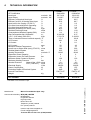
1
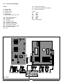
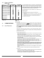
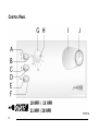
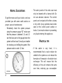
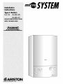
Installation
Instructions
Type C Boilers
G.C.N: 41-116-06
41-116-07
LEAVE THESE INSTRUCTIONS
WITH THE END-USER
Country of destination: GB
TABLE OF CONTENTS
1.
GENERAL INFORMATION
1.1 GENERAL INSTRUCTIONS
1.2 OVERALL VIEW
2.
INSTALLATION
2.1
2.2
2.3
2.4
2.5
2.6
2.7
2.8
2.9
2.10
2.11
2.12
REFERENCE STANDARDS
SITING THE APPLIANCE
OVERALL DIMENSIONS
CLEARANCES
MOUNTING THE APPLIANCE
ELECTRICAL CONNECTION
GAS CONNECTION
WATER CONNECTIONS
FLUE CONNECTION
ROOM THERMOSTAT CONNECTION
ELECTRICAL DIAGRAMS
GAS AND WATER CIRCUITS
3.
D.H.W. STORAGE CYLINDER
3.1 2 PORT AND 3 PORT VALVE INSTALLATIONS
3.2 DOMESTIC HOT WATER PRIORITY KIT
4.
COMMISSIONING
4.1
4.2
4.3
4.4
4.5
4.6
4.7
4.8
INITIAL PREPARATION
CONTROL PANEL
REMOVING THE FRONT PANEL
INITIAL START UP
OPERATIONAL ADJUSTMENTS
COMBUSTION ANALYSIS
FUME DISCHARGE MONITORING
DRAINING THE SYSTEM
5.
GAS ADJUSTMENTS
GAS ADJUSTMENT TABLE
5.1 CHANGING THE TYPE OF GAS
6.
MAINTENANCE
7.
TECHNICAL INFORMATION
2
1.
GENERAL
INFORMATION
This manual is an integral and essential part of the product. It should be kept
with the appliance so that it can be consulted by the user and our authorised
personnel.
Please carefully read the
instructions and notices about the
unit contained in this manual, as
they provide important information
regarding the safe installation, use
and maintenance of the product.
For operating instructions please
consult the separate User’s Manual.
1.1
GENERAL INSTRUCTIONS
Read the instructions and recommendations in these Installation Instructions
carefully to ensure proper installation, use and maintenance of the
appliance.
Keep this manual in a safe place. You may need it for your own reference
while our Servicing Centre technicians or your installer may need to consult
it in the future.
This is an appliance for the production of central heating (C.H.).
This appliance must be used only for the purpose for which it is designed.
The manufacturer declines all liability for damage caused by improper or
negligent use.
No asbestos or other hazardous materials have been used in the fabrication
of this product.
Before connecting the appliance, check that the information shown on the
data plate and the table in section 7 comply with the electric, water and gas
mains of the property. You will find the data plate on the reverse of the control
panel.
The gas with which this appliance operates is also shown on the label at the
bottom of the boiler.
Do not install this appliance in a damp environment or close to equipment
which spray water or other liquids.
Do not place objects on the appliance.
Do not allow children or inexperienced persons to use the appliance without
supervision.
If you smell gas in the room, do not turn on light switches, use the
telephone or any other object which might cause sparks.
Open doors and windows immediately to ventilate the room.
Shut the gas mains tap (at or adjacent to the gas meter) or the valve of the
gas cylinder and call your Gas Supplier immediately.
If you are going away for a long period of time, remember to shut the mains
gas tap or the gas cylinder valve.
Always disconnect the appliance either by unplugging it from the mains or
turning off the mains switch before cleaning the appliance or carrying out
maintenance.
In the case of faults or failure, switch off the appliance and turn off the gas
tap. Do not tamper with the appliance.
For repairs, call your local Authorised Servicing Centre and request the use
of original spare parts. For in-guarantee repairs contact MTS (GB) Limited.
Check the following at least once a year:
1 - Check the seals for the water connections; replace any faulty seals.
2 - Check the gas seals; replace any faulty gas seals.
3 - Visual check of the entire unit.
3
4 - Visual check of the combustion process or analysis of combustion byproducts (see section 4.5) and cleaning of the burner if needed.
5 - If called for by point. 3, dismantling and cleaning of the combustion
chamber.
6 - If called for by point. 4, dismantling and cleaning of the burner jets.
7 - Visual check of the primary heat exchanger:
- check for overheating in the blade assembly;
- clean the exhaust fan if needed.
8 - Adjustment of the flow rate of the gas: flow rate for lighting, partial load
and full load.
9 - Check of the heating safety systems:
- safety device for maximum temperature (overheat thermostat);
- safety device for maximum pressure (safety valve).
10- Check of the gas safety systems:
- safety device for lack of gas or flame ionisation (detection
electrode);
- safety device for gas cock.
11- Check of the electrical connection (make sure it complies with the
instructions in the manual).
12- General check of the combustion by-products of the
discharge/ventilation system.
13- Check of the general performance of the unit.
FIG. 1.0
1.2
OVERALL VIEW
LEGEND:
1.
2.
3.
4.
5.
6.
7.
8.
9.
10.
11.
12.
13.
14.
15.
16.
17.
18.
19.
20.
21.
22.
23.
24.
4
Flue connector
Air intake for twin pipe flue systems
Fan
Combustion chamber hood
Main heat exchanger
Safety thermostat
Combustion chamber
Combustion chamber insulation panel
Detection electrode
Ignition electrodes
Burner
Regulation thermostat
Frost thermostat
Pump pressure switch
Safety valve (3 bar)
Automatic By-pass
Gas valve
Spark generator
Boiler drain valve
Circulation pump with automatic air release valve
Expansion vessel
Air pressure take-off point
Air pressure switch
Combustion analysis points
2.
INSTALLATION
The technical information and instructions provided herein below are
intended for the installer so that the unit may be installed correctly and
safely.
2.1
REFERENCE STANDARDS
The installation and initial start up of the boiler must be by a CORGI
Registered Installer in compliance with the installation standards currently in
effect, as well as with any and all local health and safety standards i.e.
CORGI .
This appliance must be installed by a competent installer in
accordance with current Gas Safety (installation & use)
Regulations.
The installation of this appliance must be in accordance with the relevant
requirements of the current Gas Safety (installation & use) Regulations, the
Local Building Regulations, the current I.E.E. Wiring Regulations, the
byelaws of the local water authority, and in Scotland, in accordance with the
Building Standards (Scotland) Regulation and Health and Safety document
No. 635 “Electricity at work regulations 1989”.
Installation should also comply with the following British Standard Codes of
Practice:
BS 7593:1992
2.2
SITING THE APPLIANCE
Treatment of water in domestic hot water central
heating systems
BS 5546:1990 Installation of hot water supplies for domestic
purposes
BS 5440-1:1990 Flues
BS 5440-2:1989 Air supply
BS 5449:1990 Forced circulation hot water systems
BS 6789:1987 Installation of gas fired hot water boilers of rated
input not exceeding 60kW
BS 6891:1989 Installation of low pressure gas pipe up to 28mm
BS 7671:1992 IEE wiring regulations
BS 4814:1990 Specification for expansion vessels
BS 5482:1994 Installation of LPG
The appliance may be installed in any room or indoor area, although
particular attention is drawn to the requirements of the current I.E.E. Wiring
Regulations, and in Scotland, the electrical provisions of the Building
Regulations applicable in Scotland, with respect to the installation of the
appliance in a room containing a bath or shower.
Where a room-sealed appliance is installed in a room containing a bath
or shower the appliance and any electrical switch or appliance control,
utilising mains electricity should be situated so that it cannot be
touched by a person using the bath or shower.
The location must permit adequate space for servicing and air circulation
around the appliance as indicated in paragraph 2.4.
The location must permit the provision of an adequate flue and termination.
For unusual locations special procedures may be necessary.
BS 6798-1987 gives detailed guidance on this aspect.
A compartment used to enclose the appliance must be designed specifically
for this purpose. No specific ventilation requirements are needed for the
installation within a cupboard.
This appliance is not suitable for outdoor installation.
The type C appliances (in which the combustion circuit, air vent intake
and combustion chamber are air-tight with respect to the room in
which the appliance is installed) can be installed in any type of room.
Secondary ventilation is not required with this boiler. The boiler must be
installed on a solid, permanent wall to prevent access from the rear.
5
OVERALL DIMENSIONS
400 mm
2.3
LEGEND:
60 mm
A
C
E
mm
2.4
= Central Heating Flow (3/4”)
= Gas Inlet (3/4”)
= Central Heating Return (3/4”)
= Clearances
CLEARANCES
450 mm
In order to allow for access to the interior of the boiler for
maintenance pur poses, the boiler must be installed in
compliance with the minimum clearances indicated in FIG. 2.1
2.5
132
C
FIG. 2.1
E
Fasten the boiler in place using the template and anchors
supplied with the unit. It is highly recommended that a
spirit level be used to position the boiler so that it is
perfectly level.
For additional information, please consult the instructions
contained in the connection kit and the flue kit.
300 mm
132
MOUNTING THE APPLIANCE
2.6
ELECTRICAL CONNECTION
For safety purposes, have a competent person carefully
check the electrical system in the proper ty, as the
manufacturer will not be held liable for damage caused by
the failure to earth the appliance properly or by anomalies
in the supply of power. Make sure that the residential
electrical system is adequate for the maximum power
absorbed by the unit, which is indicated on the rating plate.
In addition, check that the section of cabling is appropriate
for the power absorbed by the boiler.
N
L
E
The boiler operates with alternating current, as indicated in
the technical information table in section 7, where the
maximum absorbed power is also indicated. Make sure
that the connections for the neutral and live wires
correspond to the indications in the diagram. The
appliance electrical connections are situated on the
reverse of the control panel under the inspection cover
(see the servicing manual for further information)
FIG. 2.2
IMPORTANT!
In the event that the power supply cord must be changed,
replace it with one with the same specifications. Make the
connections to the terminal board located within the
control panel, as follows:
- The yellow-green wire should be connected to the
terminal marked with the “
” symbol;
- The blue wire should be connected to the terminal
marked “N”;
- The brown wire should be connected to the terminal
6
marked “L”.
Note: The diagrams for the electrical system are indicated in section 2.12.
Warning, this appliance must be earthed.
External wiring to the appliance must be carried out by a competent person
and be in accordance with the current I.E.E. Regulations and applicable
local regulations. The microSYSTEM range of boilers are supplied for
connection to a 230 V~ 50 Hz supply.
The supply must be fused at 3 A.
The method of connection to the electricity supply must facilitate complete
electrical isolation of the appliance, by the use of a fused double pole
isolator having a contact separation of at least 3 mm in all poles or
alternatively, by means of a 3 A fused three pin plug and unswitched
shuttered socket outlet both complying with BS 1363.
The point of connection to the Electricity supply must be readily accessible
and adjacent to the appliance unless the appliance is installed in a bathroom
when this must be sited outside the bathroom (see section 2.2).
2.7
GAS CONNECTION
2.8
WATER CONNECTIONS
The local gas region contractor connects the gas meter to the service pipe.
If the gas supply for the boiler serves other appliances ensure that an
adequate supply is available both to the boiler and the other appliances
when they are in use at the same time.
Pipe work must be of an adequate size. Pipes of a smaller size than the
boiler inlet connection should not be used.
VIEW OF THE BOILER CONNECTIONS
FIG. 2.4
E
D
F
FIG. 2.3
C
SC004A
B
A
LEGEND:
A = Central Heating Flow
C = Gas Inlet
E = Central Heating Return
F = Safety Valve
G = Pump transportation screw
(remove before igniting the boiler)
H = Automatic By-pass pipe
CENTRAL HEATING
Detailed recommendations are given in BS 6798:1987 and BS 5449-1:1990,
the following notes are given for general guidance.
7
PIPE WORK:
Copper tubing to BS EN 1057:1996 is recommended for water pipes.
Jointing should be either with capillary soldered or compression fittings.
Where possible pipes should have a gradient to ensure air is carried
naturally to air release points and water flows naturally to drain taps.
The appliance has a built-in automatic air release valve, however it should
be ensured as far as possible that the appliance heat exchanger is not a
natural collecting point for air.
Except where providing useful heat, pipes should be insulated to prevent
heat loss and avoid freezing.
Particular attention should be paid to pipes passing through ventilated
spaces in roofs and under floors.
BY-PASS:
The appliance includes an automatic by-pass valve, which protects the main
heat exchanger in case of reduced or interrupted water circulation through
the heating system, due to the closing of thermostatic valves or radiator
valves within the system.
SYSTEM DESIGN:
This boiler is suitable only for sealed systems.
Drain Cocks:
These must be located in accessible positions to permit the draining of the
whole system and should be fitted at all low points. The taps must be at least
15mm nominal size and manufactured in accordance with BS 2870:1980.
SAFETY VALVE DISCHARGE:
The discharge should terminate facing downward on the exterior of the
building in a position where discharging (possibly boiling water & steam) will
not create danger or nuisance, but in an easily visible position, and not
cause damage to electrical components and wiring.
The discharge must not be over an entrance or a window or any other type
of public access.
AIR RELEASE POINTS:
These must be fitted at all high points where air naturally collects and must
be sited to facilitate complete filling of the system.
The appliance has an integral sealed expansion vessel to accommodate the
increase of water volume when the system is heated.
It can accept up to 6 litre (1.3 gal) of expansion water. If the heating circuit
has an unusually high water content, calculate the total expansion and add
an additional sealed expansion vessel with adequate capacity. This should
be located on the return pipe work as close as possible to the pump inlet.
MAINS WATER FEED - CENTRAL HEATING:
There must be no direct connection to the mains water supply even through
a non-return valve, without the approval of the Local Water Authority.
FILLING:
A temporary method for initially filling the system and replacing lost water
during servicing and initial filling (in accordance with current Water
Regulations), is provided as an integral part of the connection kit (see FIG.
2.4). The flexible hose must be removed once the system has been filled.
RESIDUAL HEAD OF THE BOILER
8
2.9
FLUE SYSTEM
The provision for satisfactory flue termination must be made in accordance
with BS 5440-1.
The appliance must be installed so that the flue terminal is exposed to outside air.
The terminal must not discharge into another room or space such as an
outhouse or lean-to.
It is important that the position of the terminal allows a free passage of air
across it at all times.
The terminal should be located with due regard for the damage or
discolouration that might occur on buildings in the vicinity.
In cold or humid weather water vapour may condense on leaving the flue
terminal.
The effect of such “pluming” must be considered.
If the terminal is less than 2 metres above a balcony, above ground or above
a flat roof to which people have access, then a suitable terminal guard must
be fitted. When ordering a terminal guard, quote the appliance model
number.
A suitable terminal guard is available from:
TOWER FLUE COMPONENTS
Morley Road
Tonbridge
Kent TN9 1RA
The minimum acceptable spacing from the terminal to obstructions and
ventilation openings are specified in FIG. 2.5.
FLUE CONNECTIONS
BC
F
G
F D
HI
J
A
E
L
K
G
TERMINAL POSITION
mm
A - Directly below an openable window or other opening
B - Below gutters, soil pipes or drain pipes
C - Below eaves
D - Below balconies or car-port roof
E - From vertical drain pipes and soil pipes
F - From internal or external corners
G - Above ground or balcony level
H - From a surface facing a terminal
I - From a terminal facing a terminal
J - From an opening in the car port
(e.g. door, window) into dwelling
K - Vertically from a terminal in the same wall
L - Horizontally from a terminal in the same wall
300
75
200
200
75
300
300
600
1200
1200
1500
300
FIG. 2.5
The boiler is designed to be connected to a coaxial flue discharge system.
Ø 60/100 mm
FIG. 2.6
9
In addition, it is also possible to use a split (twin pipe)
system by fitting a special adaptor to the flue connector
and using the aperture for the air vent intake located on
the top part of the combustion chamber.
To utilise the air intake it is necessary to:
1. Remove the bottom of the air intake by cutting it with a
suitable knife (see FIG. 2.7);
2. Insert the elbow into the air intake until it reaches the
lower end. (There is no need to use gaskets or sealing
compounds).
FIG. 2.7
Ø 80 mm
FIG. 2.8
IMPORTANT!
COAXIAL SYSTEMS
For all flue systems, a restrictor
must always be inserted into the
boiler’s flue connector; the
restrictor must be Ø 46 or Ø 41 in
diameter depending on the length
of piping indicated in TABLE 2.1.
FIG 2.9 and FIG 2.10 illustrate some
of the various designs for coaxial or
twin pipe flue systems.
For fur ther infor mation on
discharge/ventilation accessories,
see the F L U E P I P E A C C E S S O R I E S
MANUAL.
FIG. 2.9
10
Restrictor
ø 46 mm
C12 (xx)
C32 (xx)
C42 (xx)
L min = 0.5 m
L max = 1 m
Exhaust
Type
Restrictor
ø 41 mm
C12 (xx)
C32 (xx)
C42 (xx)
L min = 0.5 m
L max = 1 m
Exhaust
Type
Restrictor
ø 46 mm
C12 (xy)
C32 (xy)
C42 (xy)
L max = 25 m
34 m
34 m
34 m
3.0 m
4.5 m
12.5 m
16.0 m
C52 (xy)
C82 (xy)
L max = 22 m
31 m
3.3 m
4.8 m
14.0 m
17.8 m
Exhaust
Type
Restrictor
ø 41 mm
C12 (xy)
C32 (xy)
C42 (xy)
L max = 38 m
62 m
62 m
62 m
8m
11 m
19 m
31 m
C52 (xy)
C82 (xy)
L max = 34 m
54 m
8m
11 m
19 m
31 m
28 RFFI
Coaxial
Systems
ø 60/100
21 RFFI
Twin Pipe
Systems
ø 80/80
28 RFFI
Twin Pipe
Systems
ø 80/80
L=4m
NONE
NONE
NONE
TABLE 2.1
NONE
Risk of Condensation Forming
Maximum
Extension Piping not insulated
Piping insulated
Exhaust/Air ø 41 restrictor NO restrictor ø 41 restrictor NO restrictor
L=4m
NONE
NONE
NONE
NONE
Maximum
Risk of Condensation Forming
Extension Piping not insulated
Piping insulated
Exhaust/Air ø 46 restrictor NO restrictor ø 46 restrictor NO restrictor
Maximum
Risk of Condensation Forming
Extension Piping not insulated
Piping insulated
Exhaust/Air ø 41 restrictor NO restrictor ø 41 restrictor NO restrictor
L = Sum of the total length of exhaust + air intake piping.
21 RFFI
Coaxial
Systems
ø 60/100
Risk of Condensation Forming
Maximum
Extension Piping not insulated
Piping insulated
Exhaust/Air ø 46 restrictor NO restrictor ø 46 restrictor NO restrictor
Exhaust
Type
In calculating the lengths of the pipes, the
maximum length “L” must also take into
consideration the values for the
exhaust/air intake end terminals, as well
as 90° elbows for coaxial systems.
The C52 types must comply with the
following requirements:
1 - The exhaust/ air intake pipes must
have the same diameter of ø 80 mm.
2 - If elbows are to be inserted into the
air intake and/or exhaust system, the
calculation of the overall length must
take into consideration the values for
each elbow, see the F L U E P I P E
ACCESSORIES MANUAL.
3 - The exhaust pipe must protrude by at
least 0.5 m above the top of the roof
in the event that it is located on the
opposite side of the building to the
side with the air intake (this condition
is not obligatory when the air intake
and exhaust are located on the same
side of the building).
TWIN PIPE
SYSTEMS
FIG. 2.10
11
2.10 ROOM THERMOSTAT
CONNECTION
To connect a room thermostat and/or time clock, it is necessary to:
1. - Open the control panel as indicated in section 4.3;
2.- Remove screws “A” and remove the inspection cover from the reverse of the control
panel;
3. - For the room-thermostat connect the thermostat switching wires to the position 5 and
6 and remove the wire link (for three-wire thermostats connect the neutral to terminal
N);
4. - For the time clock connect the clock switching wires to the positions 3 and 4 and
connect the clock motor electrical supply to the terminals marked L and N.
Note: A frost thermostat is built-in to the appliance.
For connection to control systems with zone valves for hot water cylinders
see section 3.
A
12
2.11
ELECTRICAL DIAGRAM
LEGEND:
A11 - Overheat Thermostat
A12 - Spark Generator/Gas Valve Supply
A13 - Detection Electrode
A - On/Off Switch
B - On/Off L.E.D.
C - Heating Switch
D - Heating L.E.D.
E - Reset Button
F - Ignition Failure (Lockout) L.E.D.
Colours:
Wh
-White
Bl
-Blue
Gry
-Grey
Brn
-Brown
Blk
-Black
Rd
-Red
Grn/Yll -Yellow/Green
A01 - Pump Pressure Switch
A02 - Frost Thermostat
A03 - Modulator
A04 - Circulation Pump
A05 - Regulation Thermostat
A06 - External Control System
A07 - Time Clock Connector
A08 - External (Room) Thermostat
A09 - Air Pressure Switch
A10 - Fan
FIG. 2.12
13
FIG. 2.13
GAS AND WATER CIRCUITS
2.12
LEGEND:
FIG. 2.14
15
Fan
Main heat exchanger
Overheat thermostat
Burner
Ignition electrodes
Detection electrode
Regulation thermostat
Frost thermostat
Gas valve
Pump pressure switch
Safety valve (3 bar)
Boiler drain valve
Automatic by-pass
Pressure gauge
Circulation pump with automatic
air release valve
16. Expansion vessel
17. Air pressure switch
10
14
13
A. Central Heating Flow
B. Inlet Gas
C. Central Heating Return
11
12
17
1
2
16
3
4
5
6
7
8
9
14
1.
2.
3.
4.
5.
6.
7.
8.
9.
10.
11.
12.
13.
14.
15.
3.
D.H.W. STORAGE
CYLINDER
3.1
2 PORT AND 3 PORT VALVE
INSTALLATIONS
The microSYSTEM can be connected to a storage cylinder (both open-vented and
unvented) for the production of domestic hot water (D.H.W.). Cylinders of different
capacities can be used depending on site requirements (see TABLE 3.1 for a
selection of ARISTON unvented cylinders).
2 port valve installation
3 port valve installation
FIG. 3.1
FIG. 3.2
FIG. 3.3
Wiring to 2 port valve installation
using an external 2 channel
programmer
Type Danfoss FP715
Type Honeywell ST6400C
15
Wiring to 3 port valve installation
using an external 2 channel
programmer
Type Danfoss FP715
Type Honeywell ST6400C
NOTE: When using a 3 port valve installation in conjunction with an unvented cylinder it
will be necessary to use a 2 port valve on the cylinder flow connection in addition
to the 3- port valve to satisfy Building Regulations.
FIG. 3.4
TABLE 3.1
Technical Data
C.H.W.
Flow/rate
m3/h
D.H.W.
Flow/rate
It/h
Max Heating
Output
kW
Heat Ioss
It.
Coil
Surface
m2
Contract STI 125 Indirect
125
0.75
0.5
1
2
194
266
340
11.3
15.5
19.8
2
Comfort STI 125 Indirect
Contract STI 150 Indirect
125
150
0.75
0.93
0.5
1
2
256
353
451
14.9
20.5
26.2
2.2
Comfort STI 150 Indirect
Contract STI 210 indirect
150
200
0.93
0.93
0.5
1
2
256
353
451
14.9
20.5
26.2
2.4
Comfort STI 210 Indirect
Contract STI 300 Indirect
200
300
0.93
0.93
0.5
1
2
256
353
451
14.9
20.5
26.2
2.9
SB 125 Indirect
125
1
0.5
1
2
190
318
496
11
18.5
28.8
1.72
SB 150 Indirect
150
1
0.5
1
2
190
318
496
11
18.5
28.8
1.75
SB 200 Indirect
200
1.3
0.5
1
2
190
318
496
11
18.5
28.8
2.1
MODEL
Capacity
16
kWh/24h
3.2
DOMESTIC HOT WATER
PRIORITY KIT
Boiler
microSYSTEM
21 RFFI
The microSYSTEM is able to be connected to a specially designed
kit for the management of D.H.W. production. This kit gives priority to
production of D.H.W. unlike traditional systems where the boiler
power is split between C.H. and D.H.W. This generally enables a
smaller storage cylinder to be chosen as the boiler’s full output will be
channelled into the cylinder allowing for a quick heat-up.
microSYSTEM
28 RFFI
Cylinder
Contract STI 125 Indirect
Comfort STI 125 Indirect
The kit (ARISTON part number 706329) can be obtained from an
ARISTON supplier.
Contract STI 150 Indirect
Comfort STI 150 Indirect
The kit consits of:
1) Electronic module able to plug into the boiler’s P.C.B;
2) 3-way priority valve with actuator for connection to the boiler’s
flow outlet;
3) A limit thermostat (80˚C) to check the water temperature of the
heating flow to the cylinder, to be installed within the boiler;
4) Pipes and accessories.
Contract STI 210 Indirect
Comfort STI 210 Indirect
Contract STI 300 Indirect
SB 125 Indirect
SB 150 Indirect
SB 200 Indirect
TABLE 3.2
= Ideal
= Possible
4.
COMMISSIONING
4.1
INITIAL PREPARATION
MTS (GB) Limited support the
initiative. Within the information pack
you will find a copy of the
logbook. It is important that this is
completed in the presence of your customer, they are shown how to use it,
and it is signed by them. Please instruct your customer that they must have
their
logbook with them whenever they contact a service engineer
or us.
Preliminary electrical system checks to ensure electrical safety must be
carried out by a competent person i.e. polarity, earth continuity, resistance to
earth and short circuit.
FILLING THE HEATING SYSTEM:
Remove the panels of the case and lower the control panel (see section
3.3 for further information).
Open the central heating flow and return cocks supplied with the
connection kit (there are two isolation points on the return connection).
Unscrew the cap on the automatic air release valve one full turn and leave
open permanently.
Close all air release valves on the central heating system.
Gradually open valve(s) at the filling point (filling-loop) connection to the
central heating system until water is heard to flow, do not open fully.
Open each air release tap starting with the lowest point and close it only
when clear water, free of air, is visible.
Purge the air from the pump by unscrewing anticlockwise and
removing the pump plug and also manually rotate the pump shaft in
the direction indicated by the pump label to ensure the pump is free.
Refit the pump plug.
Continue filling the system until at least 1.5 bar registers on the pressure
gauge.
Inspect the system for water leaks and remedy any leaks discovered.
GAS SUPPLY:
Inspect the entire installation including the gas meter, test for soundness
and purge the supply as described in BS 6891:1988.
Open the gas cock (supplied with the connection kit) to the appliance and
check the gas connections on the appliance for leaks.
17
When the installation and filling are completed turn on the central heating
system (section 4.4) and run it until the temperature has reached the boiler
operating temperature. The system must then be immediately flushed
through.
The flushing procedure must be in line with BS 7593:1992 code of practice for
treatment of water in domestic hot water central heating systems.
During this operation, we highly recommend the use of a central heating
flushing detergent (Fernox Superfloc or equivalent), whose function is to
dissolve any foreign matter that may be in the system.
Substances different from these could create serious problems to the
pump or other components.
The use of an inhibitor in the system such as Fernox MB-1 or equivalent is
strongly recommended to prevent corrosion (sludge) damaging the boiler and
system.
Failure to carry out this procedure may invalidate the appliance
warranty.
CONTROL PANEL
4.2
LEGEND:
A
B
C
D
E
F
G
H
I
J
- On/Off button
- On/Off L.E.D. green (frost protection active)
- Central Heating button
- Cental Heating active L.E.D. green
- Ignition failure (lockout) and/or overheat reset button
- Ignition failure (lockout) and/or overheat L.E.D. red
- Central heating temperature adjustment
- Energy Saving System (ESS)
- Knock-out for time clock
- Heating system pressure gauge
4.3
FIG. 4.1
REMOVING THE
FRONT PANEL
In order to access the inside of the boiler, it is necessary to
unscrew the fastening screws “A” of the control panel
located on the lower part of the panel itself.
The control panel moves downward and when pulled
forward rotates on two lateral hinges.
The panel stays in a semi-horizontal position, which allows
access to the inner parts of the boiler.
In order to increase the manoeuvring space, it is possible
to raise the control panel and rotate it to a fully horizontal
position.
1
A
3
2
18
4
5
B
To dismantle the front casing panel it is necessary to:
1 - Remove the two screws “B”;
2 - Move the front casing panel up and lift forward.
4.4 INITIAL START-UP
4.5
THE CHECKS TO BE RUN BEFORE INITIAL START-UP ARE AS FOLLOWS:
1. Make sure that:
- the screw on the automatic air valve has been loosened when the
system is full;
- If the water pressure in the system is below 1.5 bar, bring it up to the
appropriate level;
- Ensure that the gas cock is closed;
- Make sure that the electrical connection has been made properly and
that the earth wire is connected to an efficient earthing system;
- Supply power to the boiler by pushing the On/Off button “A” (see
FIG.4.1) - the L.E.D. “B” will illuminate. Then push the button “C” in for
central heating - the L.E.D. “D” will illuminate. This will start the
circulation pump. After 7 seconds, the boiler will signal a shutdown due
to ignition failure. Leave the boiler as it is until all of the air has been bled
from the system.
- Loosen the cap on the head of the pump to eliminate any air pockets;
- Repeat the procedure for bleeding the radiators of air;
- Check the system pressure and, if it has dropped, open the filling loop
again to bring the pressure back up to 1.5 bar.
2. Make sure that all gate valves are open;
3. Turn on the gas cock and check the seals on the connections with an
approved soap solution and eliminate any leaks.
4. Press the reset button “E” for the lighting system; the spark will light the
main burner. If the burner does not light the first time, repeat the
procedure.
5. Check the minimum and maximum pressure values for the gas going to
the burner; adjust it if needed using the values indicated in the table in
section 5 (See the relative section for burner pressure adjustment within
the servicing manual).
COMBUSTION ANALYSIS
The flue connector has two apertures, readings can be
FIG. 4.2
taken for the temperature of the combustion by-products
and of the combustion air, as well as of the concentrations
of O2 and CO2, etc. .
To access these intakes it is necessary to unscrew the front
screw and remove the metal plate with sealing gasket.
To achieve the best test conditions, turn the central heating
adjustment knob “G” to the “max” position and remove the
electrical connection to the heating sensor (see section 6.).
This will allow the appliance to operate at the maximum
heating power.
19
4.6
FUME DISCHARGE
MONITORING
In the boiler, it is possible to monitor the correct operation of
the flue exhaust/air intake, checking for a loss of general
pressure in the system. Through the use of a differential
manometer connected to the test points of the combustion
chamber, it is possible to detect the ∆P of operation of the air
pressure switch.
The value detected should not be less than 0.55 mbar under
conditions of maximum thermal power in order for the boiler
to function properly and without interruption.
FIG. 4.3
4.7
BOILER SAFETY SYSTEMS
The boiler is fitted with the following devices (see section 4.2 for references).
1 - IGNITION FAILURE:
This indicates ignition failure when a flame is not detected within 7
seconds of starting an ignition sequence. The L.E.D. “F” will illuminate
to signal the shutdown status.
The system can be reset by pressing and releasing the button “E” after
checking to make sure that the gas cock is open.
2 - INSUFFICIENT SYSTEM PRESSURE:
In the event of insufficient water pressure in the heating system, a
safety device will shutdown the boiler. Check the system pressure on
the pressure gauge “J” and if it is less than 0.4 bar refill the system to
1.5 bar. Once the system pressure is at the correct level the boiler will
ignite automatically.
3 - OVERHEATING:
This control shuts off the boiler in the case where the primary circuit
reaches a temperature in excess of 105°C.
The red L.E.D. “F” will illuminate to signal this shutdown status.
The system can be reset by waiting a few minutes for the primary
exchanger to cool down and then by pressing and releasing the “E”
button.
4. ANTI-FROST DEVICE:
The boiler is equipped with a device that, in the event of the water
temperature going below 6°C, the burner ignites at the minimum power
until the boiler water reaches a temperature of 16°C.
This device operates only if the boiler is functioning perfectly and:
- the system pressure is sufficient;
- the boiler is powered electrically - L.E.D. “B” illuminated;
- the gas is turned on.
5 - EXHAUST DISCHARGE ANOMALY SHUTDOWN:
The boiler is fitted with safety devices, which in the event of defective
discharge of exhaust fumes, automatically interrupts the gas supply,
thereby shutting off the boiler.
The shutdown of the boiler is temporary and when the discharge state
of exhaust fumes has returned to normal, the boiler automatically turns
back on
4.8
DRAINING THE SYSTEM
The heating system must be emptied as follows:
- Turn off the boiler;
- Attach a hose pipe and open the drain valve;
- Empty the system at the lowest points (where present). When the heating
system is unused for an extended period of time, it is recommended that you
add antifreeze with an ethylene glycol base to the water in the
heating lines and radiators if the ambient temperature drops below 0°C during
the winter.
This makes repeated draining of the entire system unnecessary.
20
5.
GAS ADJUSTMENTS
TABLE 5.1
Methane Gas
G20
Liquid Butane Gas
G30
Liquid Propane Gas
G31
45.67
20
17
80.58
29
20
80.58
37
25
mm
m3/h
Kg/h
1.30
2.4 - 1.05
----
0.77
---1.78 - 0.78
0.77
---1.76 - 0.77
mbar
8.5 - 1.7
27.5 - 6.2
37.4 - 8.0
m3/h
Kg/h
1.30
3.15 -1.26
----
0.77
---1.78 - 0.78
0.77
---1.76 - 0.77
mbar
11.0 - 1.6
27.7 - 4.6
35.5 - 6.0
CATEGORY II2H3+
Lower Wobbe Index (15°C;1013mbar)
Nominal Delivery Pressure
Minimum Delivery Pressure
MJ/m3h
mbar
mbar
21 RFFI
Main Burner: n. 12 jets (ø)
Consumption (15°C; 1013mbar)
Consumption (15°C; 1013mbar)
Gas Burner Pressure:
max - min
28 RFFI
Main Burner: n. 14 jets (ø)
Consumption (15°C; 1013mbar)
Consumption (15°C; 1013mbar)
Gas Burner Pressure:
max - min
[1 mbar = 10,197 mmc.a.]
The outlet pressure of the gas cock is obtained by completely loosening the
screw on the solenoid. The maximum pressure of the gas to the burner will
be equal to the nominal delivery pressure minus the head loss within the
gas valve.
5.1
The boiler can be converted to use either methane (natural) gas (G20)
or LPG (G30 - G31) by an Authorised Service Centre.
The operations that must be performed are the following:
1. Replace the jets on the main burner (see table in section 5);
2. Adjust the maximum and minimum thermal capacity values for the boiler
(see table in section 5);
3. Replace the gas rating plate;
4. Adjust the maximum thermal power setting;
5. Adjust the soft-light feature (open the cover of the regulation screw on the
gas valve (see F IG . 5.1). Rotate clockwise from min. to max. as per
installation requirements).
FIG. 5.1
VG002Ab
CHANGING THE
TYPE OF GAS
21
6.
MAINTENANCE
It is recommended that the following inspections be carried out on the
boiler at least once a year:
1 - Check the seals for the water connections; replace any faulty seals.
2 - Check the gas seals; replace any faulty gas seals.
3 - Visual check of the entire unit.
4 - Visual check of the combustion process or analysis of combustion byproducts (see section 4.5) and cleaning of the burner if needed.
5 - If called for by point. 3, dismantling and cleaning of the combustion
chamber.
6 - If called for by point. 4, dismantling and cleaning of the burner jets.
7 - Visual check of the primary heat exchanger:
- check for overheating in the blade assembly;
- clean the exhaust fan if needed.
8 - Adjustment of the flow rate of the gas: flow rate for lighting, partial load
and full load.
9 - Check of the heating safety systems:
- safety device for maximum temperature (overheat thermostat);
- safety device for maximum pressure (safety valve).
10- Check of the gas safety systems:
- safety device for lack of gas or flame ionisation (detection
electrode);
- safety device for gas cock.
11- Check of the electrical connection (make sure it complies with the
instructions in the manual).
12- General check of the combustion by-products of the
discharge/ventilation system.
13- Check of the general performance of the unit.
22
23
6.
TECHNICAL INFORMATION
21 RFFI
CE Certification
Heat Input
Heat Output
Efficiency of Nominal Heat Input
Efficiency at 30% of Nominal Heat Input
Heat Loss to the Casing (∆T=50°C)
Flue Heat Loss with Burner Operating
Flue Heat Loss with Burner Off
Maximum Discharge of Fumes (G20)
Residual Discharge Head
Consumption at Nominal Capacity(G20)
Gas Consumption after 10 Minutes*
(15°C, 1013 mbar) (G30-G31)
Temp. of exhaust fumes at nominal capacity
CO2 Content
max/min kW
max/min kW
%
%
%
%
%
Kg/h
mbar
m3/h
m3
Kg/h
°C
%
O2 Content
%
CO Content
Minimum Ambient Temperature
Head Loss on Water Side (max) (∆T=20°C)
Residual Head of System
Heating Temperature
Expansion Vessel Capacity
Expansion Vessel Pre-load Pressure
Maximum Water Content of System
Maximum Heating Pressure
Nominal Pressure
Natural Gas (G20)
LPG (G30-G31)
Electrical Supply
Power Consumption
Protection Grade of Electrical System
Internal Fuse Rating
Weight
ppm
°C
mbar
bar
max/min °C
l
bar
l
bar
mbar
mbar
V/Hz
W
IP
Kg
G.C. Number
28 RFFI
63AU4549
22.7/10.0
21.0/8.7
92.8
90.8
1.2
6.0
0.2
46.2
0.70
2.4
0.32/0.39
1.78/1.76
117.2
6.81
63AU4549
29.8/12.0
27.8/10.5
93.5
90.7
0.2
6.3
0.4
60
1.60
3.15
0.37
2.34/2.31
128.8
6.9
9
8.1
20
+5
200
0.25
82/42
6
1
130
3
20
30-37
230/50
155
X4D
FAST 2 AT
39
48
+5
200
0.25
82/42
6
1
130
3
20
30-37
230/50
155
X4D
FAST 2 AT
39
41-116-06
41-116-07
Commercial subsidiary: MTS (GB) LIMITED
MTS Building
Hughenden Avenue
High Wycombe
Bucks HP13 5FT
Telephone: (01494) 755600
Fax: (01494) 459775
Internet: http://www.mtsgb.ltd.uk
E-mail: [email protected]
Technical Service Hot Line: (01494) 539579
Stampa: bieffe
Merloni TermoSanitari SpA - Italy
23 99 84 1549 000 -
Manufacturer:
RECANATI
*Calculated at 70% maximum output
Servicing
Instructions
Type C Boilers
G.C.N: 41-116-06
41-116-07
LEAVE THESE INSTRUCTIONS
WITH THE END-USER
Country of destination: GB
TABLE OF CONTENTS
2
1.
SERVICING INSTRUCTIONS
1.1
REPLACEMENT
1.2
TO GAIN GENERAL ACCESS
- Removing the front panel
- Removing the sealed chamber front cover
- Removing the side panels
1.3
ACCESS TO THE COMBUSTION CHAMBER
- Removing the combustion cover
- Removing the burner and jets
- Removing the electrodes
- Removing the main heat exchanger
- Removing the air pressure switch
- Removing the fan
1.4
SERVICING AND REMOVAL OF THE GAS VALVE
- Setting the gas pressures
- Removing the spark generator
- Removing the gas valve
1.5
ACCESS TO THE WATER CIRCUIT
- Removing the pump pressure switch
- Removing the safety valve
- Removing the automatic air vent
- Removing the pump
- Removing the pressure gauge
- Removing the expansion vessel
- Removing the overheat thermostat
- Removing the frost thermostat
- Removing the regulation thermostat
1.6
ACCESS TO THE CONTROL SYSTEM
- Checking the fuses
- Removing the P.C.B.s
2.
FAULT FINDING
2.1
FAULT FINDING GUIDE (FLOW-CHARTS)
3.
ELECTRICAL DIAGRAMS
4.
SHORT SPARE PARTS LIST
OF
PARTS
1.
SERVICING INSTRUCTIONS
To ensure efficient safe operation, it is recommended that the
boiler is serviced annually by a competent person.
Before starting any servicing work, ensure both the gas and
electrical supplies to the boiler are isolated and the boiler is
cool.
Before and after servicing, a combustion analysis should be made
via the flue sampling point (please refer to the Installation Manual
for further details).
After servicing, preliminary electrical system checks must be
carried out to ensure electrical safety (i.e. polarity, earth continuity,
resistance to earth and short circuit).
1.1
REPLACEMENT
OF
FIG. 1.4
PARTS
The life of individual components varies and they will need
servicing or replacing as and when faults develop.
The fault finding sequence chart in chapter 2 will help to locate
which component is the cause of any malfunction, and instructions
for removal, inspection and replacement of the individual parts are
given in the following pages.
1.2
2. The control panel moves downward and when pulled forward,
rotates on two lateral hinges; the panel stays in a semihorizontal position, which allows access to the inner parts of
the boiler (FIG. 1.2);
3. In order to increase the manouvering space, it is possible to
raise the control panel and rotate it to a fully horizontal position
(FIG. 1.3);
4. Remove the screws “B” from the front panel bottom lip
(FIG. 1.4);
5. Lift the front panel up and forward from the raised screws at the
the top of the casing (FIG. 1.5).
B
TO GAIN GENERAL ACCESS
All testing and maintenance operations on the boiler require the
control panel to be lowered. This will also require the removal of
the casing.
1.2.1 Removing the front panel
1. Loosen the fastening screws “A” of the control panel located on
the lower part of the panel itself. (FIG. 1.1);
FIG. 1.1
A
FIG. 1.5
FIG. 1.2
FIG. 1.3
3
1.2.2 Removing the sealed chamber front cover
1.2.3 Removing the side panels
1. Remove the screws “C” (FIG. 1.6);
2. Lift the sealed chamber front cover from the locating pins
(FIG. 1.7).
1. Remove the four screws “D” for each side panel (FIG.1.8);
2. Pull the panel away from the boiler at the base, then lift the
panel up and remove from the boiler.
FIG. 1.8
D
D
C
C
D
FIG. 1.6
FIG. 1.7
4
1.3
ACCESS TO THE COMBUSTION CHAMBER
1.3.1 Removing the combustion cover
1. Remove the screws “E” (FIG. 1.9);
2. Lift off the combustion cover.
Fig. 1.11
1.3.3 Removing the electrodes
E
E
E
Before carrying out this procedure, unscrew and slide the
burner forward (see previous section).
1. Remove rubber gasket “G” (FIG. 1.12);
2. To remove the detection electrode disconnect the cable
at its connection point close to the P.C.B. (FIG. 1.13);
FIG. 1.12
FIG. 1.9
1.3.2 Removing the burner and jets
1.
2.
3.
4.
5.
G
Remove the screws “F” from the burner (FIG. 1.10);
Remove the burner (FIG. 1.11);
Disconnect the electrodes (see section 1.3.3);
Remove the jets using a No. 7 socket spanner;
Replace in reverse order.
FIG. 1.10
F
F
FIG. 1.13
5
3. Remove screw “H” (FIG. 1.14);
4. Gently slide the electrode downward (FIG. 1.15).
1.3.4 Removing the main heat exchanger
1. Drain the boiler of water;
2. Release the overheat thermostat sensor “I” (FIG. 1.16);
3. Release the two connection nuts “J” connecting the
exchanger to the flow and return pipes (FIG. 1.17);
4. Remove the heat exchanger by sliding forward (FIG.
1.18).
FIG. 1.14
H
I
Fig. 1.16
FIG. 1.15
To replace, repeat the steps in reverse order, paying
particular attention to the following:
a - Centre the electrode in the positioning hole carefully,
otherwise the electrode may break;
b -Ensure that the left hand and right hand electrodes are
located the correct way round (facing each other), to
give the correct spark gap;
c - Check that the cables have been connected correctly;
d -Check that the rubber gasket covers the cable/ electrode
connection point completely.
J
FIG. 1.17
FIG. 1.18
6
1.3.5 Removing the air pressure switch
1.3.6 Removing the fan
1. Disconnect the electrical connections “K” and silicone
pipes “L” from their connection points (FIG. 1.19);
2. Remove screws “M” on the top of the sealed chamber
(FIG. 1.20);
3. Lift out the air pressure switch (FIG. 1.21);
4. Unscrew to remove the switch from the plate.
1. Disconnect electrical connections “N” and silicon pipe “O”
(FIG.1.22);
2. Remove screw “P” and remove the fan collar clamp “Q”
(FIG.1.23);
3. Remove screws “R” (FIG.1.24);
4. Remove fan and mounting plate (FIG.1.25).
FIG. 1.19
FIG. 1.22
K
L
N
L
O
FIG. 1.20
Q
P
M
FIG. 1.23
M
R
R
FIG. 1.24
FIG. 1.21
FIG. 1.25
7
SERVICING AND REMOVAL
OF THE GAS VALVE
1.4.1 Setting the gas pressures
1
B
A
VG002Ac
2
D
C
E
VG002Ad
3
F
VG002Af
4
G
Setting the minimum and the maximum power of the boiler
1. Check that the supply pressure to the gas valve is a minimum of 20 mbar
for natural gas. Turn off the gas supply at the isolation point under the
boiler
2. To do this, slacken the screw “A”.
Fit the pipe of the pressure gauge to the inlet pressure test point of the gas
valve “B”.
Turn on the gas supply at the isolation point under the boiler and with
the boiler running, read the inlet working pressure on the gauge.
When you have completed this operation, turn off the gas supply at the
isolation point under the boiler, remove the pressure gauge and tighten
the screw “A” securely into its housing to seal off the gas. Turn on the gas
supply at the isolation point under the boiler and test the screw for
gas escaping with an approved soap and water solution.
3. To check the pressure supplied by the gas valve to the burner, with the
boiler turned off, slacken the screw “C”. Fit the pipe of the pressure gauge
to the outlet pressure test point of the gas valve “D”.
Disconnect the compensation pipe “E”either from the gas valve or from
the sealed chamber.
4. Push the On/Off button to “ON” position -green light- and push the Heating
button to “ON” position -green lightTurn on the boiler by setting the external controls.
Adjust the 10mm nut “F” on the modureg to set the gas pressure Turn the
nut clockwise to increase and anti clockwise to decrease the pressure until
the required pressure is achieved (see TABLE A page 9)
5. To set the minimum power, disconnect the supply cable from the modureg
and adjust screw “G” whilst holding nut “F”.
Turn the screw clockwise to increase the pressure and anticlockwise to
decrease the pressure until the required pressure is achieved (see TABLE
A page 9)
6. When you have completed the above operations, turn off the external
controls, re-connect the supply terminal to the modureg on the gas valve
and replace the cap on the screw of the modureg.
Setting pressure for soft ignition.
The soft light pressure is factory set.
If the ignition is not regular (e.g: not complete burner ignition or ignition
noise) check the soft light regulator position.
The soft light pressure will need adjusting as follows:
- Turn off electrical supply;
- referring to diagram 5, open the dust cap of the soft light regulator, by
unscrewing in clockwise direction the white screw;
- turn the adjustment screw one step in the direction max to increase or in
the direction min to decrease the soft light pressure;
- after each adjustment of the regulator, turn on the electrical supply and
recheck burner ignition (wait 20 seconds between each cycle to allow
the gas valves’ internal servo system to reset). When the required level
is achieved, close the dust cap.
7. Remove the pipe from the pressure gauge and connect screw “C” to the
pressure outlet in order to seal off the gas.
8. Carefully check the pressure outlets for gas leaks (valve inlet and outlet).
5
VG002Ae
8
VG002Ab
1.4
IMPORTANT!
Whenever you disassemble
and reassemble the gas
connections, always check for
leaks using an approved soap
and water solution.
GAS BURNER PRESSURE
Regulating the heating power for
natural gas (G20)
21 kW
28 kW
OPERATING POWER
CG005A
GAS BURNER PRESSURE
Regulating the heating power for
butane gas (G30)
21 kW
28 kW
OPERATING POWER
CG004A
GAS BURNER PRESSURE
Regulating the heating power for
propane gas (G31)
21 kW
28 kW
OPERATING POWER
CG006A
21 RFFI
TABLE A
2.4
84.7
1.78
62.8
1.76
62.1
1.05
37.0
0.78
27.5
0.77
27.2
TB005A
28 RFFI
20
8.5
3.3
27.5
10.7
37.4
14.6
1.7
0.7
6.2
2.4
8.0
3.1
3.15
111.1
2.34
82.6
2.31
81.5
1.26
44.5
0.94
33.2
0.93
32.8
11
4.3
27.7
10.8
35.5
13.8
1.6
0.6
4.6
1.8
6.0
2.3
14 x 1.30
14 x 0.77
14 x 0.77
9
1.4.2 Removing the spark generator
1.4.3 Removing the gas valve
1. Disconnect ignition leads “S” by pulling upward
(FIG. 1.26);
2. Remove the screw “T” (FIG. 1.27);
3. Remove the spark generator by pulling forward from the
gas valve.
Important! Before removing the gas valve, ensure the gas
supply is turned off.
1. Disconnect all the cables from the solenoid and
modureg;
2. Remove the spark generator (see previous section);
3. Release the top nut “U” (FIG. 1.28);
4. Remove the screws “V” from the bottom of the gas valve
pipe (FIG. 1.29);
5. Remove the gas valve (FIG. 1.30).
S
U
FIG. 1.26
FIG. 1.28
V
V
T
FIG. 1.29
FIG. 1.27
FIG. 1.30
10
1.5
ACCESS TO THE WATER CIRCUIT
1. 5. 2 Removing the safety valve
Important! Before any component is removed, the boiler
must be drained of all water.
1.5.1 Removing the pump pressure switch
1. Loosen nut “Y” (FIG. 1.33);
2. Disconnect the discharge pipe work from below the
boiler;
3. Unscrew and remove the valve.
1. Remove the cable of the pump pressure switch “W”
(Fig. 1.31);
2. Unscrew the pump pressure switch by using a spanner
on the nut “X”(FIG. 1.32);
3. Remove the pump pressure switch.
Y
FIG. 1.33
W
FIG. 1.31
1.5.3 Removing the automatic air vent
1. Unscrew valve top “Z” (FIG. 1.34);
2. Remove valve complete with float (FIG 1.35).
Z
X
FIG. 1.32
FIG. 1.34
FIG. 1.35
11
1.5.4 Removing the pump
1.
2.
3.
4.
5.
6.
Remove the U-clips “ A1” and “B1” (FIG. 1.36);
Remove the retaining clip “C1” (FIG. 1.37);
Release the nut “D1” (FIG. 1.38);
Remove the pipe “E1” (FIG. 1.39);
Remove the screw “F1” (FIG. 1.40);
Remove the pump (FIG. 1.41).
A1
E1
FIG. 1.39
B1
F1
FIG. 1.36
FIG. 1.40
C1
FIG. 1.37
FIG. 1.41
D1
FIG. 1.38
12
1.5.5 Removing the pressure gauge
1.5.6 Removing the expansion vessel
1. Remove the U-clip “G1” and remove the pressure gauge
coupling (FIG. 1.42);
2. Push the pressure gauge through the control panel from
the rear (FIG. 1.43).
1.
2.
3.
4.
Release nuts “H1” and remove the gas pipe (FIG. 1.44);
Release nut “I1” (FIG. 1.45);
Remove lock-nut “J1” (FIG. 1.46);
Remove the expansion vessel (FIG. 1.47).
H1
G1
H1
FIG. 1.44
FIG. 1.42
I1
FIG. 1.45
FIG. 1.43
J1
FIG. 1.46
FIG. 1.47
13
1.5.6 Removing the overheat thermostat
1. Disconnect the overheat thermostat electrical
connections “K1” (FIG. 1.48);
2. Then remove the thermostat from its mounting by
releasing the securing clip (FIG. 1.49).
FIG. 1.51
K1
1.5.8 Removing the regulation thermostat
FIG. 1.48
1. Remove the regulation thermostat sensor from its
mounting by releasing the securing clip “M1” (FIG. 1.52);
2. Separate the facia panel from the rear of the control
panel (see section 1.6.2);
3. Remove the electrical connections “N1 from the
regulation thermostat (FIG. 1.53);
4. Pull the regulation knob from the spindle of the
thermostat;
5. Remove the thermostat from the control panel facia by
unscrewing the mounting screws.
FIG. 1.49
M1
1.5.7 Removing the frost thermostat
1. Disconnect the frost thermostat electrical connection
“L1” (FIG. 1.50);
2. Then remove the thermostat from its mounting by
releasing the securing clip (FIG. 1.51).
FIG. 1.52
L1
N1
FIG. 1.50
14
FIG. 1.53
1.6
ACCESS TO THE CONTROL SYSTEM
1.6.2 Removing the P.C.B.s
Important! Isolate the electrical supply to the boiler before
accessing the control panel.
1.6.1 Checking the fuse
1. Isolate electricity;
2. Remove the screws “O1” (FIG. 1.56);
3. Separate the facia panel from the rear of the control
panel;
4. Unplug all electrical connections from the P.C.B. and
remove the screws “P1” and remove the P.C.B. (FIG.
1.57).
1. Remove the inspection cover on the reverse of the
control panel (FIG. 1.54);
2. Remove the fuse mounted on the reverse of the
inspection cover (FIG. 1.55).
O1
O1
O1
O1
O1
O1
FIG. 1.56
FIG. 1.54
P1
P1
P1
P1
FIG. 1.57
FIG. 1.55
15
2.
FAULT FINDING
2.1
FAULT FINDING GUIDE
(FLOW-CHARTS)
It is possible to detect and correct any defect by using the standard fault
finding diagrams described in this chapter.
PRELIMINARY
CHECKS
MAKE SURE THAT :
1 - THERE IS SUFFICIENT
WATER IN THE SYSTEM
2 - THE GAS IS TURNED ON
3 - T HE ELECTRICAL SUPPLY
IS TURNED ON
PRESS THE
ON/OFF BUTTON
IS
THE SUPPLY
L.E.D. ILLUMINATED?
NO
1 - CHECK THE FUSES
2 - CHECK THERE IS POWER
SUPPLIED TO THE P.C.B.S
3 - CHECK/REPLACE THE P.C.B.
(CT1)
YES
PRESS
THE CENTRAL
HEATING BUTTON
IS
THE L.E.D.
ILLUMINATED?
NO
1 - CHECK THE INTEGRITY
OF THE L.E.D.
2 - CHECK/REPLACE THE P.C.B.
(CT1)
YES
IS THE
TIME CLOCK/
PROGRAMMER
AND/OR ROOM THERMOSTAT
CALLING FOR
HEATING?
YES
NO
FROST
PROTECTION IS
ACTIVATED <5¡C. IS THE
FROSTPROTECTION
REQUESTED?
NO
A
16
FC002Aa
YES
B063
A
IS THE PUMP
RUNNING?
NO
YES
POWER T O
THE PUMP?
NO
YES
1 - CHECK THE PUMP CABLE
2 - CHECK/REPLACE P.C.B.
(CT1)
3 - CHECK THE SYSTEM
PRESSURE GAUGE IS AT
1.5 BAR
1 - CHECK THE OPERATION
OF THE PUMP
2 - RELEASE/REPLACE THE
PUMP
IS THE FAN
RUNNING?
YES
NO
BOILER
SHUTDOWN?
YES
1 - RESET THE BOILER
NO
B
1 - CHECK/REPLACE AIR
INTERNAL
P.C.B. PROTECTION
ACTIVATED?
YES
23-
PRESSURE SWITCH
AND CABLE
CHECK IF THE RESET
IS JAMMED
CHECK/REPLACE
DETECTION ELECTRODE
NO
1 - CHECK/REPLACE FAN
POWER T O
THE FAN?
NO
CONNECTION CABLE
2 - CHECK/REPLACE P.C.B.
3 - CHECK/REPLACE AIR
PRESSURE SWITCH
YES
FC002Ab
1 - REPLACE THE FAN
B063
17
B
IS THE
AIR PRESSURE SWITCH
ACTIVATED?
NO
1 - CHECK AIR PRESSURE
SWITCH CABLE
2 - CHECK/REPLACE AIR
PRESSURE SWITCH
3 - CHECK/REPLACE P.C.B.
(CBM2)
∆P≤0.5 mbar
YES
DOES
THE SPARK
SEQUENCE
START?
∆P 0.5 mbar
CHECK
∆P ON PRESSURE
TEST POINT
1234-
CHECK EXHAUST DISCHARGE
CHECK VENTURI AND TUBES
CHECK THE FAN EFFICIENCY
REPLACE FAN
1 - CHECK/REPLACE IGNITION
ELECTRODES
2 - CHECK THE CABLES
3 - CHECK SPARK GENERATOR
4 - CHECK IGNITION ELECTRODE
NO
5 - C HECK /R EPLACE P.C.B. (CBM2)
CABLES
YES
1 - CHECK POWER SUPPLY
IS THE BURNER
ALIGHT?
TO
THE GAS VALVE
NO
2 - CHECK OPERATION
OF THE
4 - CHECK/REPLACE P.C.B. (CBM2)
GAS VALVE
3 - REPLACE THE GAS VALVE
YES
HAS THE
BOILER SAFETY
SHUTDOWN BEEN
ACTIVATED?
YES
PRESS THE RESET
BUTTON
1 - CHECK IF THE FLAME
NO
BOILER
WORKING?
NO
23-
STRIKES THE DETECTION
ELECTRODE
CHECK THE SOFT-LIGHT
GAS PRESSURE
CHECK/REPLACE DETECTION
ELECTRODE
4 - CHECK/REPLACE
P.C.B. (CBM2)
YES
NORMAL
OPERATION
POSSIBLE CAUSES
FAULT LIST
1 NOISEY OPERATION
- MAIN HEAT EXCHANGER FAULTY OR BLOCKED
WITH LIME-SCALE DEPOSITS
- LOW HEATING SYSTEM WATER PRESSURE
- CHECK GAS PRESSURES
- CHECK HEATING THERMOSTAT
- CHECK FAN
- CHECK PUMP
YES
NO
NORMAL
OPERATION
2 DECREASE/INCREASE OF HEATING
3 REPEATED
SHUTDOWNS
4 REPEATED
OPERATION OF SAFETY THERMOSTAT
5 INSUFFICIENT RADIATOR
18
CIRCUIT
PRESSURE
TEMPERATURE
-
CHECK FOR LEAKS ON THE HEATING CIRCUIT
FAULTY FILLING LOOP
FAULTY EXPANSION VESSEL
FAULTY DETECTION ELECTRODES
CHECK GAS PRESSURES
CHECK FLAME DETECTION ELECTRICAL CIRCUIT
FAULTY HEATING THERMOSTAT
FAULTY OVERHEAT THERMOSTAT
PRESENCE OF AIR IN THE HEATING CIRCUIT
CHECK BURNER PRESSURES
CHECK EXCHANGER FLUEWAY
CHECK HEATING THERMOSTAT
CHECK BY-PASS
CHECK GAS PRESSURE
FC002Ac
IS
THERE STILL
A PROBLEM?
B063
3.
ELECTRICAL
DIAGRAMS
LEGEND:
A - On/Off Switch
B - On/Off L.E.D.
C - Heating Switch
D - Heating L.E.D.
E - Reset Button
F - Ignition Failure (Lockout) L.E.D.
A01
A02
A03
A04
A05
-
Pump Pressure Switch
Frost Thermostat
Modulator
Circulation Pump
Regulation Thermostat
A06
A07
A08
A09
A10
A11
A12
A13
- External Control System
- Time Clock Connector
- External (Room) Thermostat
- Air Pressure Switch
- Fan
- Overheat Thermostat
- Spark Generator/Gas Valve Supply
- Detection Electrode
Colours:
Wh
-White
Bl
-Blue
Gry
-Grey
Brn
-Brown
Blk
-Black
Rd
-Red
Grn/Yll -Yellow/Green
SE011A
B063
19
SF008A
20
B063
4.
SHORT SPARE
PARTS LIST
microSYSTEM 21/28 RFFI
71 11 70 69 68
67 66 65 64 11 63
62
61
304
1
60
59
2
3
72
4
64
5
6
7
11
64
11
73
74
8
107
301
64
106
105
302
303
58
9
57
104
10
103
75
11
12
12
11
56
102
76
55
54
101
77
100
79
80
78
98
80
97
95
13
94
81
82
13
53
52
51
96
99
50
83
14
47
93
15
16
17
88
87
84
47
46
45
92
91
31
13
19
13
86
48
89
90
85
49
18
19
20
21
22 23
24
13
25 26 27 28 29 30 31 32 33 34 35 36
37 38 39 38 37 38 40 41 42 43 44
33
352
351
354
B063
21/28 RFFI
ES002A
353
21
microSYSTEM 21/28 RFFI
Key
no.
2
5
13
16
18
19
21
22
23
25
26
27
29
30
31
33AB
33CD
45
48
49
55
60AB
60CD
73
75
76AB
76CD
78AB
78CD
81
83A
83B
83C
83D
87AC
87BD
93
95
97
98
99
351
352
353
354AB
354CD
361
362
22
G.C. part
no.
164 282
164 225
164 229
164 261
E03 818
E24 076
E24 075
ARISTON
Part No.
Description
Expansion vessel
Gasket 3/8"
Gasket 3/4"
Thermostat (frost)
Flow group
Gasket 1/2"
Safety valve (1/4" 3 bar)
Gasket 1/4"
Pump pressure switch
Spark Generator
Gasket
Gas valve
Auto air vent
Return group
O-ring
Pump
Pump
Thermostat (regulation)
P.C.B. (CBM2 AT-FFI2X)
Pressure gauge
Gasket
Air pressure switch
Air pressure switch
Gasket
O-ring (2.65 x 10.27)
Fan
Fan
Main exchanger
Main exchanger
Thermostat (overheat)
Burner 12 ramp (natural gas)
Burner 12 ramp (LPG)
Burner 14 ramp (natural gas)
Burner 14 ramp (LPG)
Burner jet (natural gas 1.30)
Burner jet (LPG 0.77)
P.C.B. (CT1)
Fast fuse 2AT
Electrode (ignition R.H.)
Electrode (ignition L.H.)
Detection electrode
O-ring (A.A.V.)
Auto air vent
Gasket (pump head)
Pump head
Pump head
Burner jet 1.30 full kit (natural gas)
Burner jet 0.77 full kit (LPG)
1
1
1
1
1
1
1
1
1
1
1
1
1
1
1
1
1
1
1
1
1
1
1
1
1
1
1
1
1
1
1
1
1
1
1
1
1
998616
573521
573520
570760
998612
573528
998447
569390
998627
999542
574279
999475
998809
999476
998424
998836
999091
999577
999499
999245
998517
998484
571651
997182
998943
998489
999894
998620
998893
999538
998618
998669
998887
998939
998433
998434
999501
950030
998623
998622
998624
998644
998643
998738
998961
999207
998716
998717
B063
NOTES
B063
23
Merloni TermoSanitari SpA - Italy
Commercial subsidiary: MTS (GB) LIMITED
MTS Building
Hughenden Avenue
High Wycombe
Bucks HP13 5FT
Telephone: (01494) 755600
Fax: (01494) 459775
Internet: http://www.mtsgb.ltd.uk
E-mail: [email protected]
Technical Service Hot Line: (01494) 539579
23 99 84 1550 000 -
Manufacturer:
Users
Manual
Dear Customer,
Thank you for choosing an ARISTON boiler.
We guarantee that your boiler is a reliable
and technically sound product.
This
User's
Manual
provides
detailed
instructions and recommendations for proper
installation, use and maintenance.
Remember to keep this manual in a safe place
The guarantee on this appliance is
valid for 12 months from the first
day of installation.
Repairs to the electric, hydraulic or
gas circuits may be carried out only
by your local authorised MTS
Servicing Centre.
for future reference i.e. by the gas meter.
Your local MTS Servicing Centre is at your
complete disposal for all requirements.
Every attempt has been made to avoid
errors of any kind
in this User's Manual, the Management
invites customers to inform
of any inaccuracies which they may find.
This will help to improve our service
2
TABLE OF CONTENTS
1.
2.
3.
4.
5.
6.
GENERAL INFORMATION
page 4
Technical Information
page 5
Control Panel
page 6
OPERATING INSTRUCTIONS
USEFUL INFORMATION AND TROUBLESHOOTING
MAINTENANCE
CHANGE OF GAS TYPE
TIME CLOCK
page 7
page 12
page 15
page 15
page 15
IMPORTANT!
Please read this manual carefully.
For additional information, please consult the “Installation and Servicing
Instructions.”
Make sure to keep the manuals provided with the appliance so that they can
be used by the end-user, installer or our authorised engineer.
3
1. GENERAL INFORMATION
MTS (GB) Limited support the
initiative. Your installer will give you, and
show you how to use, a logbook which will
give you important information about your
boiler, and heating system. Please have this
logbook to hand whenever you contact a
service engineer or us.
All CORGI Registered Installers carry a
CORGI ID card, and have a registration
number. Both should be recorded in your
boiler Logbook. You can check your installer
is CORGI registered by calling CORGI direct
on :- (01256) 372300.
This is an appliance for the production of
central heating. This appliance must be used
only for the purpose for which it is designed.
The manufacturer declines all liability for
damage caused by improper or negligent use.
4
Do not allow children or inexperienced
persons to use the appliance without
supervision.
If you smell gas in the room, do not turn on
light switches, use the telephone or any other
object which might cause sparks.
Open doors and windows immediately to
ventilate the room.
Shut the gas mains tap (on the gas meter) or
the valve of the gas cylinder and call your Gas
Supplier immediately.
If you are going away for a long period of
time, remember to shut the mains gas tap or
the gas cylinder valve.
Before any intervention within the boiler it is
first necessary to cut off the electrical power
supply by turning the external switch to
“OFF”.
TECHNICAL INFORMATION
10 kW
15 kW
21 kW
28 kW
kW
kW
%
11.6
10.5
81.3
15.4
14.1
82.4
22.7-10.0
21.0-8.7
83.7
29.8-12.0
27.8-10.5
84.2
CENTRAL HEATING
Operating Temperature max-min
Maximum-Minimum Heating Pressure
Built-in expansion vessel - Total capacity
°C
bar
litres
82-42
3-0.7
6
82-42
3-0.7
6
82-42
3-0.7
6
82-42
3-0.7
6
ELECTRICAL DATA
Electrical Supply/Frequency
Power Consumption
Protection of Electrical System
V/Hz
W
IP
230/50
105
X4D
230/50
115
X4D
230/50
105
X4D
230/50
155
X4D
CATEGORY
Nominal Pressure/Methane Gas (G20)
Nominal Pressure/Liquid Gas (G30-G31)
mbar
mbar
20
30-37
20
30-37
20
30-37
20
30-37
GENERAL DATA
Heating input max-min
Heating output max-min
Efficiency at Maximum Thermal Capacity
(see Installation Instructions)
5
CONTROL PANEL
10 RFFI / 15 RFFI
21 RFFI /28 RFFI
6
FR011A
LEGEND:
A
B
C
D
E
F
G
H
I
J
- On/Off button
- On/Off L.E.D. green (frost
protection active)
- Central Heating button
- Cental Heating active
L.E.D. green
- Ignition failure (lockout)
and/or overheat reset button
- Ignition failure (lockout) and/or
overheat L.E.D. red
- Central heating temperature
adjustment
- Energy Saving System (ESS)
- Knock-out for time clock
- Heating system pressure gauge
2. OPERATING INSTRUCTIONS
CAUTION
Installation, start-up, adjustments and
maintenance must be performed by a
competent person only, in accordance
with the current Gas Safety (Installation &
Use) Regulations and the instructions
provided. Improper installation may
cause damage or injury to individuals,
animals and personal property, for which
the manufacturer will not be held liable.
To ensure efficient and safe operation it is
recommended that the boiler is serviced
annually by a competent person.
If it is known or suspected that a fault
exists on the appliance, it must not be
used until the fault has been corrected by
a competent person.
7
HELPFUL SUGGESTIONS
To get the most out of your boiler, we have
provided you with some useful advice on
proper use and maintenance:
- Periodically check the system pressure
using the pressure gauge “J”, make sure
that the pressure is between 1.0 and 1.5
bar (the blue part on the gauge) when the
system is off and cool. Consult your installer
for checking and refilling the system if the
pressure value is under 1.0 bar.
J
UT013Af
8
- The outer panels of the units case must
only be cleaned with a damp cloth. Do
not use abrasive cleaners. The control
panel can be wiped with either a damp
or dry cloth. Spray polishes must not be
used on the control panel surface or
knobs. Care must be taken in preventing
any liquid entering the appliance.
PRACTICAL
TIPS
- If the water is very hard, it is
recommended that a scale reducer be
added to the system so as to reduce the
formation of limescale in the boiler heat
exchanger. This will ensure that the
efficiency of the unit remains the same
over time, reducing gas consumption
Ignition procedure
Push the button “A” the green L.E.D. “B”
will illuminate indicating that the boiler is
supplied with electricity.
UT013Aa
A
B
Push the button “C” the green L.E.D. “D”
will illuminate indicating that the boiler is
operating for central heating production.
C
UT013Ab
and maintenance costs.
- If the boiler should be out of use for a
prolonged period, it is recommended
that the electrical power supply be
disconnected and that the external gas
cock be closed. If low temperatures are
expected, the boiler and system pipe
work should be drained in order to
prevent frost damage.
- To improve comfort and take full
advantage of the heat produced by the
boiler, it is recommended that an
external (room) thermostat be installed.
- It is good practice to clean and service
the appliance and central heating
system every year.
Call an Authorised Service Centre.
D
9
UT013Ac
E
F
10
Adjusting the heating
It is possible to set the temperature of the
heating system by adjusting the knob “G”
between 1 and 5 until the stop on the
“ECO” position. This will vary temperature
from approximately 40˚C to about 65˚C.
To obtain a higher temperature it is
necessary to turn the Energy Saving System
(ESS) screw “H” clockwise with a small
coin. The knob is now free to turn to the
MAX position,
which represents G
a temperature of
about 80°C.
UT013Ad
The centralised electronic control unit will
ignite the burner, without any manual
intervention but in response to the request
for heating. If, after approximately 10
seconds, the burner has not ignited, the
boiler safety devices will shut off the gas
and the red L.E.D. “F” illuminates. To reset
the ignition system, the reset button “E”
must be pressed and released. Should the
boiler fail to ignite a second time, check
that the external gas cock is open. If the
problem persists, contact an Authorised
Service Centre.
Turning off central heating
If an external (room) thermostat is installed,
it is recommended that the temperature of
the heating system be set (by means of the
knob “G”) at the “ECO” position. This will
allow the regulation of the external
temperature to operate effectively and
obtain energy efficiency and good
performance
from the boiler.
To turn off the central heating, push the “C”
button and the green L.E.D. ”D” will go off.
The boiler will remain electrically supplied
and frost protection will be active for
temperatures below 6°C.
C
UT013Ab
External (room) thermostat
control
D
UT013Ag
G
11
Turning off the boiler
To turn the boiler off, push the button “A”
the respective green L.E.D. “B” will go off.
Close the gas cock located under the boiler
and turn the electricity supply switch
(located outside the boiler) to the OFF
position.
B
UT013Aa
A
3. USEFUL INFORMATION
AND TROUBLESHOOTING
Boiler shutdown situations
The boiler is equipped with safety devices
that intervene in certain situations and shut
it off. Most of these situations are
communicated by means of the red
L.E.D.“F” and at times the user may be able
to remedy them.
Shutdown due to ignition failure
In the event that the automatic ignition of
the burner has failed, the red L.E.D. “F” will
illuminate. In order to reset the ignition, the
button “E” must be pressed and released.
12
UT013Ac
E
F
Shutdown due to overheating
In the event that the safety limit is exceeded
for the temperature of the water in the
boiler’s primary exchanger, the thermostat
shuts off the boiler and the red L.E.D. “F”
illuminates.
To remedy this situation, wait a few minutes
to allow the exchanger to cool down, then
press and release the reset button “E”.
If this situation occurs frequently, contact an
Authorised Service Centre.
Shutdown due to insufficient
system pressure
In the event of insufficient water pressure in
the heating system, a safety device will
shutdown the boiler. Check the system
pressure on the pressure gauge “J” and if
it is less than 0.4 bar refill the system to 1.5
bar (consult your
J
installer for checking
and
refilling
the
system). Once the
system pressure is at
UT013Af
Should the boiler fail to ignite a second
time, check that the external gas cock is
open. If the problem persists, contact an
Authorised Service Centre.
13
the correct level the boiler will ignite
automatically. If there are frequent drops in
pressure within the system, have a plumber
check the heating system for possible water
leaks.
Temporary shutdown due to
defective discharge of exhaust
fumes
discharge state of exhaust fumes has
returned to normal, the boiler automatically
turns back on.
Important!
If this situation occurs frequently, contact an
Authorised Service Centre. so that they
may check that the exhaust fumes are
being expelled correctly and that the area
is ventilated properly.
Frost protection
The boiler is fitted with safety devices,
which in the event of a defective discharge
of exhaust fumes, automatically interrupts
the gas supply, thereby shutting off the
boiler.
The shut-off of the boiler is temporary for a
period of about 15 minutes.
Once this time period has passed and the
The boiler is fitted with a thermostat which,
in the event that the water temperature
goes below 6°C, the burner turns on at
minimum power until the water in the boiler
has reached a temperature of about 20°C.
This device is only activated when the
boiler is operating perfectly and:
14
- the system pressure is sufficient;
- the boiler is powered electrically;
- gas is being distributed.
4. MAINTENANCE
Schedule an annual maintenance check-up
for the boiler with a competent person.
Correct maintenance always results in
savings in the cost of running the system.
5. CHANGE OF GAS TYPE
the other, one of our Authorised Service
Centres should be contacted.
6. TIME CLOCK
A time clock for central heating is available
as an accessory kit and can be mounted
via the knock-out “I”. The installation of this
should only be
undertaken by a I
competent person
and in accordance
with
the
kit
instructions.
Our boilers are designed to function either
with Natural Gas (methane) or LPG gas. If
you need to changeover from one gas to
15
Merloni TermoSanitari SpA - Italy
Commercial subsidiary:
MTS (GB) LIMITED
MTS Building
Hughenden Avenue
High Wycombe
Bucks HP13 5FT
Telephone: (01494) 755600
Fax: (01494) 459775
Internet: http://www.mtsgb.ltd.uk
E-mail: [email protected]
Technical Service Hot Line: (01494) 539579
Cod. 23 99 84 1548 112
Manufacturer: