1
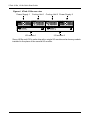
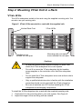
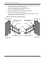
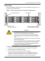
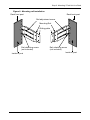
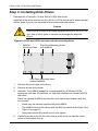
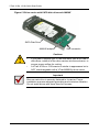
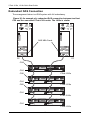
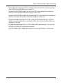
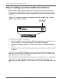
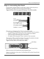
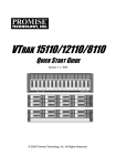
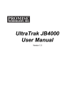
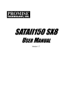
VTRAK
J610s, J310s
QUICK START GUIDE
Version 1.0
© 2007 Promise Technology, Inc. All Rights Reserved.
VTrak J610s, J310s Quick Start Guide
VTrak Task List
Step 1: Unpacking the VTrak (below).
Step 2: Mounting VTrak in a Rack
•
VTrak J610s (page 5)
•
VTrak J310s (page 7)
Step 3: Installing Disk Drives (page 10)
Step 4: Setting Up Data Cable Connections (page 14)
Step 5: Setting Up Serial Cable Connections (page 20)
Step 6: Connecting the Power (page 21)
Step 7: Setting Up the CLI Connection (page 22)
Step 1: Unpacking the VTrak
The VTrak J610s or J310s box contains the following items:
•
VTrak J610s or J310s Unit
•
Quick Start Guide
•
Front bezel and key
•
RJ11-to-DB9 serial data cable
(Units with one I/O module: 1)
(Units with two I/O modules: 2)
•
1.0m (3.3 ft) SAS cable
(Units with one I/O module: 1)
(Units with two I/O modules: 2)
•
Screws for disk drives
(J610s: 70, including 6 spares)
(J310s: 50, including 2 spares)
•
Left and right mounting rails
•
Left and right center-mount brackets
•
1.5m (4.9 ft) Power cords (2)
•
CD with Product Manual and Quick
Start Guide
Warning
The electronic components within the J610s and J310s units are
sensitive to damage from Electro-Static Discharge (ESD).
Observe appropriate precautions at all times when handling the
J610s or J310s unit or its subassemblies.
2
Step 1: Unpacking the VTrak
Figure 1. VTrak J610s front view with bezel removed
Drive Carrier LEDs
Drive Carriers
Power and Status LEDs
Figure 2. VTrak J610s rear view
I/O module 1
I/O module 2
115200
8N1
Power Supply 1
115200
8N1
Cooling Unit 1 Cooling Unit 2 Power Supply 2
Figure 3. VTrak J310s front view with bezel removed
Drive Carrier LEDs
Drive Carriers
Power and Status LEDs
3
VTrak J610s, J310s Quick Start Guide
Figure 4. VTrak J310s rear view
Cooling Unit 1 Cooling Unit 2 Power Supply 2
Power Supply 1
O
O
I
I
115200
8N1
115200
8N1
I/O module 2
I/O module 1
Some J610s and J310s units ship with a single I/O module and a dummy module
installed in the place of the second I/O module.
4
Step 2: Mounting VTrak Unit in a Rack
Step 2: Mounting VTrak Unit in a Rack
VTrak J610s
The J610s subsystem installs to the rack using the supplied mounting rails. You
can also use your existing rails.
Figure 5. VTrak J610s mounted in a rack with the supplied rails
Vertical Rack Post
VTrak J610s
Mounting rails (included)
mount outside the rack post
Handles mount
outside the rack post
Cautions
•
At least two persons are required to safely lift, place, and
attach the VTrak subsystem into a rack system.
•
Do not lift or move the VTrak subsystem by the handles,
power supplies or the controller units. Hold the subsystem
itself.
•
Do not install the VTrak subsystem into a rack without rails to
support the subsystem.
•
Only a qualified electrician who is familiar with the installation
procedure should mount and install the VTrak subsystem.
•
Be sure all switches are OFF before installing the VTrak
subsystem or exchanging components.
To install the J610s subsystem into a rack with the supplied mounting rails:
1.
Check the fit of the mounting rails in your rack system. See Figure 6.
2.
Adjust the length of the mounting rails as needed.
5
VTrak J610s, J310s Quick Start Guide
3.
Attach the mounting rail assemblies to the outside of the rack posts, using
the attaching screws from your rack system.
Be sure the support is on the bottom facing inward.
4.
Square the rail assemblies in the rack.
5.
Tighten the adjustment screws and the attaching screws.
6.
Place the VTrak subsystem onto the rails.
7.
Secure the VTrak subsystem to the rack through each handle, using the
attaching screws from your rack system.
Figure 6. Rack mount assembly diagram
Rack front post
Rack back post
Rail attaching screw
(not included)
Rail attaching screw
(not included)
Front rail
Rear rail
Flange
Support
Rail adjustment screw
Rail adjustment screw
Inside of post
Inside of post
6
Step 2: Mounting VTrak Unit in a Rack
VTrak J310s
The J310s subsytem installs to the rack using the supplied mounting rails. You
can also use your existing rails.
Figure 7. VTrak J310s mounted in a rack with the supplied rails
VTrak J310s
Vertical Rack Post
Handles mount
outside the rack post
Mounting rails (included)
mount outside the rack post
Cautions
•
At least two persons are required to safely lift, place, and
attach the VTrak subsystem into a rack system.
•
Do not lift or move the VTrak subsystem by the handles,
power supplies or the controller units. Hold the subsystem
itself.
•
Do not install the VTrak subsystem into a rack without rails to
support the subsystem.
•
Only a qualified electrician who is familiar with the installation
procedure should mount and install the VTrak subsystem.
•
Be sure all switches are OFF before installing the VTrak
subsystem or exchanging components.
To install the VTrak subsystem into a rack with the supplied mounting rails:
1.
Check the fit of the mounting rails in your rack system. See Figure 9.
2.
Slide the plates out of the mounting rails.
3.
Attach one plate to each side of the VTrak subsystem.
Line-up the six holes in the plate with the corresponding holes in the
subsystem. Attach each plate with six screws (included). See Figure 8.
4.
Slide one of the rails over the plate on one side of the enclosure.
7
VTrak J610s, J310s Quick Start Guide
The rail is designed to slide freely over the plate.
5.
Attach a flange to each end of the rail, with the rail on the opposite side of the
flange from the two-hole bracket.
6.
Install the rail adjustment screws (included) through the flange into the rail.
There are four screws for each flange. See Figure 9.
7.
Place the subsystem with mounting rails into your rack system.
8.
Attach the mounting rail assemblies to the outside of the rack posts, using
the attaching screws from your rack system.
9.
Square the rail assemblies in the rack.
10. Tighten the adjustment screws and the attaching screws.
11. Place the VTrak subsystem onto the rails.
12. Secure the VTrak subsystem to the rack through each handle, using the
attaching screws from your rack system.
Figure 8. Sliding flange installation
Rear (connector end)
of the subsystem
VTrak J310s
Sliding plate
Screws (6 each side)
8
Step 2: Mounting VTrak Unit in a Rack
Figure 9. Mounting rail installation
Rack front post
Rack back post
Rail adjustment screw
Mounting Rail
Sliding plate
Rail attaching screw
(not included)
Rail attaching screw
(not included)
Inside of post
Inside of post
9
VTrak J610s, J310s Quick Start Guide
Step 3: Installing Disk Drives
Populate the VTrak with 3.5-inch SAS or SATA disk drives.
Install all of the drive carriers into the J610s or J310s enclosure to ensure proper
airflow, even if you do not populate all the carriers with disk drives.
Caution
Use only the counter-sink screws supplied with the J610s or J310s
unit. Use of other types of screws can damage the adjacent
drives.
Figure 10.J610s and J310s unit drive carrier mounting holes
Counter-sink screws only.
Disk Drive Mounting Holes
with AAMUX
WARNING:
AAMUX
Mounting Holes
Disk Drive Mounting Holes
without AAMUX
1.
Remove the front bezel (drive door).
2.
Remove a disk drive carrier.
3.
Optional. The AAMUX adapter is recommended for J610s and J310s
enclosures with two I/O modules, so that both modules can access a SATA
disk drive.
Place the optional AAMUX into the disk drive carrier and attach it with the
four screws.
4.
•
Install only the screws supplied with the AAMUX.
•
The AAMUX fits into the carrier with the SAS connector at the back. See
Figure 6 on page 12
•
Snug each screw. Be careful not to over tighten.
Carefully lay the drive into the drive carrier at the front, so that the screw
holes on the bottom line up.
10
Step 3: Installing Disk Drives
If you installed an AAMUX, lay the SATA disk drive in the carrier and slide it
so the power and data connectors insert in to the AAMUX. See Figure 10 on
page 12.
5.
Insert the screws through the holes in the drive carrier and into the bottom of
the disk drive (see Figure 5).
•
Install only the screws supplied with the VTrak.
•
Install four screws per drive.
•
Snug each screw. Be careful not to over tighten.
6.
Reinstall the drive carrier into the VTrak chassis.
7.
Repeat steps 2 through 5 until all of your disk drives are installed.
8.
Replace the front bezel.
Figure 11.Drive carrier with SAS disk drive
SAS Disk Drive
11
VTrak J610s, J310s Quick Start Guide
Figure 12.Drive carrier with SATA disk drive and AAMUX
SATA Disk Drive
AAMUX adapter
SAS connector
Cautions
•
If you plan to operate your VTrak with fewer than a full load of
disk drives, install all of the drive carriers into the enclosure, to
ensure proper airflow for cooling.
•
A VTrak J610s or J310s carrier is similar in appearance but is
NOT interchangeable with a VTrak M500f/i/p drive carrier.
Important
Be sure each drive is securely fastened to its carrier. Proper
installation ensures adequate grounding and minimizes vibration.
Do not install drives with fewer than four screws.
12
Step 3: Installing Disk Drives
Drive Numbering
Each disk drive in the J610s and J310s units is identified by a number that
corresponds to the Port number used for management. For more information,
see Chapter 3 of the VTrak J610s, J310s Product Manual on the CD.
Numbers are stamped above each drive bay for easy indentification.
Figure 13.VTrak J610s drive slot numbering
1
2
3
5
4
6
9
10
13
8
7
11
12
15
14
16
Figure 14.VTrak J310s drive slot numbering
1
2
9
4
3
5
6
8
7
10
11
13
12
VTrak J610s, J310s Quick Start Guide
Step 4: Setting Up Data Cable Connections
The VTrak J610s or J310s unit provides Direct Attached Storage (DAS) support
to the Host PC.
Figure 15. VTrak J610s has one or two I/O modules
I/O module 1
(default primary)
I/O module 2
115200
8N1
115200
8N1
Figure 16.VTrak J310s has one or two I/O modules
O
O
I
I
115200
8N1
115200
8N1
I/O module 1
(default primary)
I/O module 2
There can be one or two Input Output Modules (I/O modules) on the J610s or
J310s unit.
•
If your J610s or J310s has two I/O modules, I/O module 1 (on the left) is the
default primary.
•
If your J610s or J310s has only one I/O module, that I/O module is the
default primary.
Under SAS specifications, both I/O modules are active at the same time. The
terms primary and secondary are for enclosure management purposes only. To
verify which I/O module is the default primary, see Chapter 3 of the VTrak J610s,
J310s Product Manual on the CD.
14
Step 4: Setting Up Data Cable Connections
Figure 17.VTrak J610s and J310s I/O modules have one subtractive-routed
port and one table-routed port
115200
8N1
Table Connector (CN2) LED
Subtractive Connector (CN1) LED
I/O Module Status LED
Each I/O module has one subtractive-routed external receptacle (CN1) and one
table-routed external receptacle (CN2).
Note
SAS HBA cards are User-supplied items. They are not included
with the VTrak unit.
15
VTrak J610s, J310s Quick Start Guide
Basic DAS Connection
Figure 18. An example of a basic DAS connection between one Host PC
and one VTrak J310s unit. The J610s is similar
Subtractive-Routed Port
O
O
I
I
115200
8N1
115200
8N1
VTrak J310s
SFF-8088 external
4X to 4X SAS cable
SAS HBA Card
PC
The arrangement above is the minimum DAS system with a single SAS HBA
card in the Host PC. Connect the SAS card to the table-routed port (CN1) on the
I/O module.
Use a SFF-8088 4X to 4X external SAS cable with thumbscrew connectors
(supplied with the J610s or J310s unit).
Because the Host SAS HBA card is an end device, you can connect it to either of
the two SAS ports (CN1 or CN2) on the J610s or J310s unit’s I/O module.
16
Step 4: Setting Up Data Cable Connections
Cascading DAS Connection
If you are using multiple J610s or J310s units and want to manage them from the
same SAS HBA card, connect the J610s or J310s units in a cascade.
Connect the SAS HBA card in the Host PC to the subtractive-routed port (CN1)
of the I/O module. Use a SFF-8088 4X to 4X external SAS cable (supplied with
the J610s or J310s unit).
Connect the I/O module’s table-routed port (CN2) on the first J610s or J310s unit
to the subtractive-routed port (CN1) on the next J610s or J310s unit. You can
cascade up to four J610s or J310s units in this manner. You can mix J610s and
J310s units in the same cascade.
Figure 19. An example of a cascaded DAS connection between one Host
PC and three VTrak J310s units. The J610s is similar
SAS HBA Card
PC
CN2
CN1
O
O
I
I
115200
8N1
115200
8N1
VTrak J310s
CN1
O
O
I
I
115200
8N1
115200
8N1
VTrak J310s
17
VTrak J610s, J310s Quick Start Guide
Redundant DAS Connection
The arrangement below is a DAS system with full redundancy.
Figure 20. An example of a redundant DAS connection between two Host
PCs and four cascaded VTrak J310s units. The J610s is similar
SAS HBA Cards
PC
PC
CN2
O
O
I
I
CN1
115200
8N1
115200
8N1
VTrak J310s
CN2
O
O
I
I
CN1
115200
8N1
CN2
115200
8N1
VTrak J310s
O
O
I
I
CN1
115200
8N1
115200
8N1
VTrak J310s
CN1
O
O
I
I
115200
8N1
115200
8N1
VTrak J310s
18
Step 4: Setting Up Data Cable Connections
The arrangement requires J610s or J310s units with dual I/O modules and two
Host PCs with a SAS HBA card in each PC.
Connect the SAS HBA card in the first Host PC to the subtractive-routed port
(CN1) on a I/O module of the first J610s or J310s unit.
Connect the SAS HBA card in the second Host PC to the subtractive-routed port
(CN2) on the other I/O module of the first J610s or J310s unit.
Connect the table-routed ports (CN2) on the I/O modules of the first J610s or
J310s unit to the subtractive-routed ports (CN1) on the I/O modules of the next
J610s or J310s unit.
Connect the remaining J610s or J310s units in the same manner. You can mix
J610s and J310s units in the same cascade.
Use SFF-8088 to SFF-8088 SAS cables to connect the J610s or J310s units.
19
VTrak J610s, J310s Quick Start Guide
Step 5: Setting Up Serial Cable Connections
RS232 serial communication enables the Command Line Interface (CLI) and
Command Line Utility (CLU) on your PC to monitor and control the VTrak. On
VTrak, RS232 communication goes through the RJ11 serial connector on each
controller.
Figure 21. A serial connector is located on the I/O module. The J310s is
shown. The J610s is similar
RJ11 Serial
Connector
115200
8N1
O
O
I
I
115200
8N1
115200
8N1
To set up a serial cable connection:
1.
Attach the RJ11 end of the RJ11-to-DB9 serial data cable, supplied with the
VTrak, to the RJ11 serial connector on one of the I/O modules.
2.
Attach a null-modem cable to the DB9 end of the RJ11-to-DB9 serial data
cable.
3.
Attach the other end of the null-modem cable to a serial port on the Host PC
or Server.
If your PC has two DB9 COM ports, and your J610s or J310s unit has two I/O
modules, you can connect a second null-modem cable and RJ11-to-DB9 serial
data cable the I/O module on the right.
See “Step 4: Setting Up Data Cable Connections” on page 14 for an explanation
of which I/O module is the default primary. To verify which I/O module is the
default primary, see Chapter 3 of the VTrak J610s, J310s Product Manual on the
CD.
20
Step 6: Connecting the Power
Step 6: Connecting the Power
Plug the power cords and switch on both power supplies. When the power is
switched on, the LEDs on the front of the VTrak will light up.
Figure 22.VTrak J310s front panel LED display. The J610s is similar
Power
FRU Status
Not Used
I/O module-1 activity
I/O module-2 activity
Heartbeat
When boot-up is finished and the VTrak is functioning normally:
•
The heartbeat LED blinks green once every 3 seconds if one I/O module is
installed, or twice every 3 seconds if two I/O modules are installed.
•
Power and FRU LEDs display green continuously.
•
I/O module LEDs flash green if there is activity on that connection.
There are two LEDs on each Drive Carrier. They report the presence of power
and a disk drive, and the current condition of the drive.
Figure 23.VTrak J610s/J310s disk carrier LEDs
Disk Status
Power/Activity
Within one minute, the Power/Activity should display Green.
If there is no disk drive in the carrier, the Disk Status LED and the Power/Activity
LED will remain dark.
21
VTrak J610s, J310s Quick Start Guide
Step 7: Setting Up the CLI Connection
The J610s or J310s unit has a Command Line Interface (CLI) to manage all of its
functions, including customization. Access the CLI via your PC’s terminal VT100
or ANSI emulation program, such as Microsoft HyperTerminal.
With the J610s or J310s unit running and the RJ11-to-DB9 serial data cable with
a null-modem cable connected to the primary I/O module:
1.
2.
3.
Change your terminal emulation program settings to agree with the
following:
•
Bits per second: 115200
•
Data bits: 8
•
Parity: None
•
Stop bits: 1
•
Flow control: none
Start your PC’s terminal emulation program.
Press Enter once to launch the CLI.
The cli> prompt on your screen indicates that you have a connection and the
CLI is ready to accept commands.
CLI Command Set
The CLI has the following set of commands:
cable – Specifies the length of cable for optimal signal quality.
enclosure – Displays full information on the J310s or J610s unit and all its
components, expander addresses and SAS addresses.
help – Use alone or with a command, such as help enclosure, enclosure -help
or enclosure -h.
link – Displays the current status of the Phys (links) and the error counter.
route – Displays addresses of components through a downstream (expansion)
connection.
uptime – Displays the number of days, hours, minutes and seconds since the
firmware was loaded (the VTrak was started or restarted).
vpdr – Displays vital product data on field replaceable units.
? – Use alone or with a command, such as ? enclosure or enclosure -?.
Note
Commands are case-sensitive. Disable the Caps Lock on your
keyboard.
22
Frequently Asked Questions
Frequently Asked Questions
What kind of disk drives can I use with J610s and J310s?
The J610s and J310s support 3.5-inch Serial Attached SCSI (SAS) disk
drives.
How can I tell when the J610s or J310s unit has fully booted?
When the J610s or J310s unit is fully booted up, the Power and FRU LEDs
will light up green. If a disk array is present, the Logical Drive LED will light
up green also. The heartbeat LED blinks green once every 3 seconds if one
I/O module is installed, or twice every 3 seconds if two I/O modules are
installed.
How can I tell my CLI connection is to the primary default I/O module?
After you establish the CLI connection, type Enclosure and press Enter. Look
at the top of the display for an item called I/O Module Role. If the Role is
Active, you are connected to the default primary I/O module. If the Role is
StandBy, you are connected to the default secondary.
What happens if a disk drive fails?
Depending on the nature of the failure, the failed drive the drive might not
appear in the CLI, or the failed drive might appear with an error, when you
run the enclosure command or the link command. See the VTrak J610s,
J310s Product Manual on the CD for more information.
Can I hot-swap a failed drive with a new one?
Yes. Disk drives are hot-swappable on the J610s and J310s units.
Can the J610s and J310s run using just one power supply?
Yes, it is possible to run J610s and J310s unit on a single power supply.
J610s and J310s units ship with two power supplies. The J610s or J310s
unit will continue running if one of the power supply fails. But deliberately
leaving one power supply off negates this advantage.
In addition, leaving one power supply off reduces air flow through the J610s
or J310s enclosure and can contribute to overheating. Always switch on both
power supplies.
23
VTrak J610s, J310s Quick Start Guide
Contact Technical Support
Promise Technical Support provides several support options for Promise users to
access information and updates. We encourage you to use one of our electronic
services, which provide product information updates for the most efficient service
and support.
Important
Promise offers 24x7 live technical support (in English only) for
registered owners of VTrak products. To register, point your
browser to:
http://www.promise.com/support/warranty/
warranty_eng_pdchoose.asp
If you decide to contact us, please have the following information available:
•
Product model and serial number
•
BIOS, firmware and driver version numbers
•
A description of the problem / situation
•
System configuration information, including: motherboard and CPU type,
hard drive model(s), SAS/SATA/ATA/ATAPI drives & devices, and other
controllers.
Technical Support Services
Promise Online™ Web Site
Promise Online™ eSupport
http://www.promise.com/support
(technical documents, drivers, utilities, etc.)
https://support.promise.com/support
(online request form)
United States
E-mail Support
[email protected]
Fax Technical Support
(408) 228-1097 Attn: Technical Support
Phone Technical Support
(408) 228-1400 option 4
If you wish to write us for
support:
Promise Technology, Inc.
Attn: Technical Support
580 Cottonwood Drive
Milpitas, CA 95035, USA
24
Contact Technical Support
Europe, Africa, Middle East
E-mail Support
[email protected]
Fax Technical Support
+31 (0) 40 256 9463 Attn: Technical Support
Phone Technical Support
+31 (0) 40 235 2600
If you wish to write us for
support:
Promise Technology Europe B.V.
Attn: Technical Support
Science Park Eindhoven 5542
5692 EL Son, The Netherlands
Germany
E-mail Support
[email protected]
Fax Technical Support
+49 (0) 2 31 56 76 48 - 29
Attn: Technical Support
Phone Technical Support
+49 (0) 2 31 56 76 48 - 10
8:30am-5:00pm M-F Germany Time
If you wish to write us for
support:
Promise Technology Germany
Attn: Technical Support
Europaplatz 9
44269 Dortmund, Germany
Italy
E-mail Support
[email protected]
Fax Technical Support
0039 06 367 12400 Attn: Technical Support
Phone Technical Support
0039 06 367 12626
If you wish to write us for
support:
Promise Technology Italy
Attn: Technical Support
Piazza del Popolo 18
00187 Roma, Italy
25
VTrak J610s, J310s Quick Start Guide
Taiwan
E-mail Support
[email protected]
Fax Technical Support
+886 3 578 2390 Attn: Technical Support
Phone Technical Support
+886 3 578 2395 (ext. 8811)
If you wish to write us for
support:
Promise Technology, Inc.
Attn: Technical Support
2F, No. 30, Industry E. Rd. IX
Science-based Industrial Park
Hsin-Chu 30075, Taiwan (R.O.C.)
China
E-mail Support
[email protected]
Fax Technical Support
+86-10-8857-8015 Attn: Technical Support
Phone Technical Support
+86-10-8857-8085/8095
If you wish to write us for
support:
Promise Technology China
Attn: Technical Support
Room 1205, Tower C
Webok Time Center, No.17
South Zhong Guan Cun Street
Hai Dian District, Beijing 100081, China
26