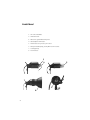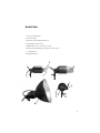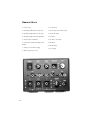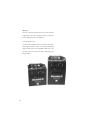
1
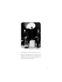
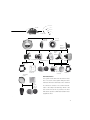
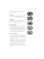
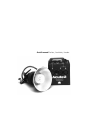
Acute2 manual Profoto, Stockholm, Sweden.
Warning
Profoto generators and lamp heads are parts of a complete
professional lighting system. Please read the instruction
manual carefully before use. Flash tubes and modelling
lamps emit considerable heat and may cause injury if not
handled properly.
Note, always unplug the lamp cable from the generator
before changing the modelling lamp or flash tube.
• Under no circumstances are generators or heads to be
opened.High voltage is inside the equipment.
• Do not touch hot metal parts.
• Do not obstruct ventilation
• Do not connect flash heads with the protective cap in place
When using the flash, do not place filters, diffusing materials, or any other obstructions directly onto the glass cover,
flash tube or modelling lamp.
Never position the light extremely close to people.
When mounting umbrellas, do not touch the flash tube or
modelling lamp with the metal shaft – risk of high voltage.
Never connect accessories of other brands without consulting an authorised service station.
Service only to be performed by an authorised repair station!
Always use a grounded mains outlet.
Note! Under no circumstances is any part of the equipment
to be opened! The equipment is not user-serviceable and
there is dangerous high voltage inside!
Contents
Thanks! . . . . . . . . . . . . . . . . . . . . . . . . . . . . . . . . . . . . 4
The Acute2 System Chart . . . . . . . . . . . . . . . . . . . . . . . 6
Acute2 head . . . . . . . . . . . . . . . . . . . . . . . . . . . . . . . . 8
Acute2 twin . . . . . . . . . . . . . . . . . . . . . . . . . . . . . . . . . 9
The flash heads . . . . . . . . . . . . . . . . . . . . . . . . . . . . . . 10
Acute2 head . . . . . . . . . . . . . . . . . . . . . . . . . . . . . . . . 11
Acute2 twin . . . . . . . . . . . . . . . . . . . . . . . . . . . . . . . . . 12
Acute2 ring . . . . . . . . . . . . . . . . . . . . . . . . . . . . . . . . . 13
Nomenclature . . . . . . . . . . . . . . . . . . . . . . . . . . . . . . . 14
Brief instructions . . . . . . . . . . . . . . . . . . . . . . . . . . . . . 15
Energy distribution . . . . . . . . . . . . . . . . . . . . . . . . . . . 17
Energy distribution Acute2 twin . . . . . . . . . . . . . . . . . . 20
Energy control . . . . . . . . . . . . . . . . . . . . . . . . . . . . . . . 21
Gas generator . . . . . . . . . . . . . . . . . . . . . . . . . . . . . . . 24
Troubleshooting guide . . . . . . . . . . . . . . . . . . . . . . . . . 26
Technical data . . . . . . . . . . . . . . . . . . . . . . . . . . . . . . . 27
The Acute2 system consists of the following products:
Generators:Acute2 1200, Acute2 2400
Heads: Acute2 head, Acute2 twin, Acute2 ring
All Profoto reflectors and accessories fit the Acute2 system.
3
Thanks!
Thanks for showing us your confidence by investing in an Acute2 system. For more than
three decades we have sought the perfect light. What pushes us is the conviction that we can
offer even the most demanding photographer yet better tools.
Before our products are shipped we have them pass an extensive and strict testing program. We check that they pass the quality and capacity levels the most demanding photographers require. For this reason our flash equipment is the standard in most rental studios
in New York and Tokyo and the most rented flash all over the world. The system consists
of a variety of generators built and designed to meet the demands of the most demanding
photographers on this planet. Yet the most important thing is the light you create and it is
then essential that the system offers freedom to create your own light. The Acute2 heads in
particular offer you this possibility . The light source, both the flash tube and the modelling
light, is placed high and free in the flash head. This makes it easier for you to adjust the light
and use your creativity. The reflectors are moveable and lock easily into place. By moving
the position of the reflector you can get a higher or lower concentration of light in the center
or more of a flood light. This is not new, of course. Our flash heads have always been designed
that way. What is new, however, is our new glass cover, which is designed to increase precision. The Acute2 head and the Acute2 twin are supplied with a frosted and UV-coated cover
glass, which together with the flash tube, produce a colour temperature adapted to daylight
colour film. There are glass covers with varying filtration, for greater diversity.
The whole Acute2 system is modular. Every single reflector and accessory creates its
special light and the unique Profoto focusing system offers you a possibility to create your
own light with only a few different reflectors.
4
Profotos founders Eckhard Heine och Conny Dufgran,
At ”Photokina”,Cologne, Germany 1968
”A photographer’s tools are a natural part of the creative process. Like a painter’s brush, an artist’s chisel or
a musician’s instrument, their form and design should
reflect their function, they should have the right feel, and
they should be aesthetically pleasing”.
5
Acute 2
Acute2 1200
Acute2 2400
Acute2 Flash Extension Cable
Acute2 head
Acute2 twin
Narrow
Beam travel
Reflector
Softlight
Reflector Silver
Softlight
Reflector white
ProGlobe
w/clips
Honeycomb
Grid
Glass
Kit
ProGlobe
w/Chimera
Disc
Reflector
Adapter
Plate
5 and 7 foot
Reflector
ProZoom
ProFocus
ProBox
ProFresnel
White
Pattern
Holder &
Pin Set
6
Heat absorbing
Iris
filter
Diaphragm
60x60
Slide
holders
24x36
Barn Doors
for ProFresnel
Transparent
Silver
ProGas
Power Cable
Acute2 ring
Close-up
Reflector
Softlight
Reflector
Narrow
Beam travel
Reflector
Zoom Reflector
7” Grid Reflector
Barn Doors
Narrow
Beam
Reflector
13”
Bell Reflector
Magnum Reflector
7” Grid
Pro Tube
FilterHolder
40x40 cm
Grid & Filter
Holder
10° Honeycomb Grid
BarnDoor
The Acute2 series
The system chart shows how the wide Profoto
line of accessories fit together with generators
Filter
Cassette
Snoot
5°, 10° &
20° Grid
and heads. Reflectors and heads can be combined
in a number of varieties. The common denominator is the lamp head diameter, which is the
base of the Profoto line of products. The lines
indicate the possible combinations that Profoto
equipment offers.
7
Acute2 head
1. UV reduced flash tube
2. Umbrella holder
3. Manoeuvre system with locking lever
4. Stand adapter 16mm (5/8")
5. Acute2 Glass Cover, frosted, UV-coated
6. Halogen modelling lamp, 250W, Mini-can E11 socket
7. Locking springs
8. Zoom reflector
1
5
6
7
3
2
8
8
4
Acute2 twin
1. UV reduced flash tubes
2. Umbrella holder
3. Manoeuvre system with locking lever
4. Stand adapter 16mm (5/8")
5. PB/Twin Glass Cover , frosted, UV-coated
6. Halogen modelling lamp, 500W, Mini-can E11 socket
7. Locking springs
8. Magnum Reflector
1
6
5
7
3
2
4
8
9
The flash heads
All Profoto lamp heads are designed for maximum light shaping purposes. The light source (both the flash tube and the modelling lamp) is mounted high and free in the flash head. This
makes it easier for you to adjust the light and use your creativity.
The flash head has a built in holder for the umbrella.
The reflectors lock easily into place and by moving the reflector
different types of light shaping is achieved. All Profoto reflectors and accessories fit the Acute2 heads.
A UV-reduced quartz flash tube is included with all Acute2
heads. The flash tube has two metal pins. When removing a
flash tube, pull it straight out of the sockets. When inserting
a new flash tube, check that the trigger wire clasps properly
around the flash tube (please see mounting instructions in package).
In case the head overheats the modelling light automatically
switches off. When the temperature has dropped sufficiently the
modelling light will switch on again.
NOTE!
Always unplug the lamp cable from the generator before changing modelling lamp or flash tube.
10
Acute2 head
The Acute2 head is fan cooled and it has an automatic voltage
selector for the fan. The dimmer controlled modelling light is
powered directly from the mains and it is therefore important
to check that the rated voltage for the lamp corresponds with
the mains supply. A 250 W E11 Mini-can halogen lamp is
included in standard deliveries. The Acute2 head is supplied
with a frosted UV-coated glass cover and a Zoom reflector.
Combined with the UV-reducing quartz flash tube the frosted glass cover offers the recommended colour temperature
for daylight type film. Distinctive colour temperature adjustments can be obtained by combining glass covers with different coatings. The following glass covers are available:
10 15 33
Glass Cover, frosted, UV-coated (standard)
10 15 35
Glass Cover, frosted, extra UV-coated, -300°K
10 15 34
Glass Cover, frosted, uncoated
10 15 37
Glass Cover, clear, UV-coated
10 15 39
Glass Cover, clear, extra UV-coated, -600°K
10 15 36
Glass Cover, clear, uncoated
10 20 02
250W, 120V Halogoen, Mini-Can
10 20 13
250W, 240V Halogen, Mini-Can
11
Acute2 twin
The Acute2 twin is used to obtain even shorter flash duration,
very quick recycling or to fire 4800 Ws out of one single head.
An Acute2 twin has two flash tubes. As the flash duration is
shorter at low power switch settings, and as only half of the
desired power is used in each tube, consequently shorter flash
duration is obtained.
If you require shorter flash duration and you for example need
1200 Ws, you connect the Acute2 twin to the B sockets on the
Acute2 1200 generator and fire 600 Ws from each tube. The
flash duration is shorter than if a standard Acute2 head is used.
The flash duration at 1200 Ws with an Acute2 head is 1/560
while it is only 1/1000 with an Acute2 twin.
If, on the contrary, you require faster recycling, you power the
Acute2 twin with 2 Acute2 generators. The recycling is faster
since each generator need to recharge less energy.
To get 4800 Ws from one head you connect the Acute2 twin to
two Acute2 2400 generators.
Flash duration and recycling for an Acute2 twin at a certain
power setting - for example 1200 Ws - compares with a Acute2
head powered with 600 Ws.
Since the modelling light is powered from the mains
supply it is important to check that the rated voltage for
the modelling lamp corresponds with the mains supply.
The modelling light is a 500W Halogen with a Mini-can socket
(E11). The flash tube has two metal pins. When removing a
flash tube, pull it straight out of the sockets. When inserting
a new flash tube, check that the trigger wire clasps properly
around the flash tube (please see mounting instructions in
package).
12
10 15 18
10 15 19
10 15 20
10 15 21
10 20 07
10 20 15
Glass Cover, frosted, UV-coated (standard)
Glass Cover, frosted, extra UV-coated, -300 gr K
Glass Cover, frosted, uncoated
Glass Cover, clear, UV-coated
500W, 120V, Halogen, Mini-can
500W, 240V, Halogen, Mini-can
Acute2 ring
The Acute2 ring is an entirely mobile source of light. The
interior diameter of 100mm provides plenty of space for professional camera lenses. Since the camera holder can be tilted
forward and backwards, as well as upwards and downwards,
most cameras can be attached. The Acute 2 ring gives a
shadowless light and it makes an excellent source of light in
cramped areas, such as the interior of an automobile. Many
fashion photographers also use the Acute 2 ring to find new
angles and capture details. The ring flash provides a very
distinct, directed light, but can be complemented by a soft light
reflector, which increases the light source, thereby producing a
soft light with little shadow.
For close-ups, there is a reflector that focuses the light 50 cm
in front of the camera lens.
The maximum charge is 9600 Ws/minute. This means 4 flashes
a minute at 2400 Ws, 8 flashes at 1200 Ws, 16 flashes at
600 Ws, etc.
Changing flash tube is only to be done at a professional
service station.
Mounting the reflector:
•Remove the two ridged screws fixating the camera holder.
•Remove the four ridged nuts holding the outer and inner
reflectors together.
•Run the lamp cable through the outer reflector and let the
reflector slide into position.
•Reassemble the outer and inner reflectors using the ridged
nuts.
•Reassemble the camera holder using the two ridged
screws.
10 06 42 Softlight Reflector Ring
10 06 43 Close-Up Reflector Ring
13
Nomenclature
1. Power On/Off
9. Sound Switch
2. Modelling Light Dimmer for Group A
10. Slave (Photocell) Switch On/Off
3. Modelling Light Dimmer for Group B
11. Photocell and IR
4. Modelling Light Control Max/Dim/Off
12. A-Switch
5. Ready Lamp & Test Button
13. A+B/A<->B Switch
6. Fast/Slow Recharging and Amp. draw
14. B-switch
Button
15. Bracket Dial
7. Voltage Selector Mains Supply
16. Sync Input
8. Mains Frequency Selector
2
1
7
6
12
3
13
5
4
8
14
10
9
15
11
16
14
14
17. Flash head socket (group A)
18. Mains connection
19. Flash head socket(group B)
17
18
19
20
20. Flash head socket(group B)
Brief instructions
• Check that the voltage you have selected on generator
corresponds with the mains supply voltage
• Check that the modelling lamp has the correct voltage
• Connect flash head/s
• Connect the mains supply cable
• Choose recycling time
• Switch on the POWER
• Switch on modelling light (MOD. LIGHT)
• Choose energy distribution
• Adjust the modelling light
• Press the ready lamp/test button for flash
• Connect sync cable
15
Warning!
Never use ordinary household extension cords to extend the
length of the power cable. They may overheat. Contact your
Profoto distributor for proper equipment.
Connecting lamp heads
One, two or three lamp heads can be connected to the sockets
marked A, B and B (15). When connecting the lamp plug,
align the white dots on the plug with the white dot on the
generator panel. Secure by turning the locking ring on the
plug clockwise.
16
Energy distribution
The energy can be controlled over a 6 f-stop range or 7 when
using 2 heads connected to the B sockets. The energy output
through the outlets A (17) and B (19,20) is controlled by the
A+B / A<->B switch (13), the
(17) ( 19)
(20)
(12)
(13)
(14)
(15)
switches A and B (12+14) and the dial BRACKET (15).
The nominal energy of the flash unit is divided equally into
two groups, A and B, and the two groups can either be
combined or separated with the A+B / A<->B switch (13).
The energy in group A is controlled by the A-switch (12) and
the energy in group B is controlled by the B-switch (14).
In each group the energy can be halved or quartered.
Please see panel for details.
Below you will find detailed description on how to control
the energy if you use one, two or three Acute2 heads or if
you use a Acute2 twin.
Always start with settin g the BRACKET dial(15) to max,
the A- and B switch at full and the A+B / A<->B switch
(13) in position A+B. You now have maximum energy.
Full f-stop changes are done with the A- or/and B-switch.
Fine adjustments or further f-stop reductions are done with
the BRACKET dial.
17
Energy distribution
One head
1. Connect the head to socket A.
2. Reduce the energy one f-stop by switching A+B / A<- >B
switch to position A<- >B.
3. Further reduce the energy one or two f-stops by halving or
quartering the energy with the A-switch.
4. Use the dial BRACKET for fine adjustments and to further
reduce the energy by two f-stops.
Two heads
Symmetrical light distribution
1. Connect the two heads to the B sockets.
2. Reduce the energy one f-stop by switching A+B / A< -> B
switch to position A<- >B.
3. Further reduce the energy one or two f-stops by halving or
quartering the energy with the B-switch.
4. Use the dial BRACKET for fine adjustments and to further
reduce the energy by two f-stops.
Asymmetrical light distribution
1. Connect one head to the A socket and one head to one
of the
B sockets.
2. Set the A+B / A <-> B switch in position A<->B.
The energy for the two heads is now individually controlled.
3. Reduce the energy one or two f-stops by halving or quartering the energy with the A-switch for the head connected to
the A-socket.
18
4. Use the dial BRACKET for fine adjustments and to further reduce
the energy by two f-stops.
Three heads
Symmetrical light distribution
1. Connect one head to each socket
2. Set the A+B / A< - >B switch in position A+B. The energy for
the two groups is now added and then equally divided between
the connected heads.
3. Reduce the light output by reducing the energy with A- and Bswitch.
5. Use the dial BRACKET for fine adjustments and to further
reduce the energy by two f-stops.
Asymmetrical light distribution
1. Connect one head to each socket
2. Set the A+B / A< - >B switch in position A< -> B. The energy
for the two groups is now individually controlled.
3. Reduce the energy for the head connected to socket A by one or
two f-stops by halving or quartering the energy with the A-switch.
4. Reduce the energy for the heads connected to sockets B by one
or two f-stops by halving or quartering the energy with the
B-switch. The energy in group B is equally divided between the
two heads.
5. Use the dial BRACKET for fine adjustments and to further
reduce the energy by two f-stops.
19
Energy distribution Acute2 twin
One generator
1. Connect the head sockets to the two B sockets on the
generator.
2. Reduce the energy one f-stop by switching A+B / A<->B
switch to position A<->B.
3. Further reduce the energy one or two f-stops by halving or
quartering the energy with the B-switch.
4. Use the dial BRACKET for fine adjustments and to further
reduce the energy by two f-stops.
Two generators
1. Connect the head socket to socket A on each generator.
2. Reduce the energy one f-stop by switching A+B / A<-> B
switch to position A< -> B on both generators.
3. Further reduce the energy one or two f-stops by halving or
quartering the energy with the A-switch on both generators.
4. Use the dial BRACKET for fine adjustments and to further
reduce the energy by two f-stops on both generators.
20
Energy Control
With the dial BRACKET (15) the total energy can, irrespective
of the energy distribution, be reduced to 1/4, i.e. two f-stops.
The flash duration, recycling and colour temperature is affected by using the dial BRACKET. When using the bracketing dial
(15) to reduce the energy you need to dump excess energy by
pushing down the test button (5). To obtain the shortest
possible flash duration use the position max and reduce energy
by using the energy switches.
Bracketing
The BRACKET DIAL can also be used to obtain alternative
exposures - "bracketing".
1. Turn the dial to -1. Find your correct f-stop with your flash
meter. Make the first exposure.
(5)
2. Turn the dial to max. The power increases to an overexposure
of one f-stop . Make the second exposure.
(15)
3. Turn the dial to -2 energy. Press the test button (5). After
recharging the power is decreased to an underexposure of one
f-stop.
4. Now make the third exposure.
This procedure results in three different exposures. One is "correct", one is overexposed by one f-stop and one is underexposed
by one f-stop. There are three different exposures without any
change in lighting or depth of field.
It is of course possible to choose only1/4 or 1/2 of an f-stop
"bracketing". The distance between marks is 1/4 of an f-stop.
21
Charging and recycling
Check that the voltage selector (7) and the frequency selector(8) matches the mains supply voltage. Turn on the main
(7)
switch POWER (1).
The recycling time is very short. Variations may occur depending on the selected flash energy and the mains power supply.
The shortest recycling time is obtained with low flash energy
(8)
selected with the A-, B- and A+B / A<->B-switches and the
BRACKET (15) dial.
(15)
Flash duration
The shortest flash duration is obtained by using an Acute2 twin
connected to the B sockets, the BRACKET dial set to 1/1,
the A+B/A<->B switch to the A<->B position and the B
switch set at 1/4.
(11)
Photo Cell
The built-in photo cell (11) will sense flash release as well as
IR-signals from most IR-transmitters. The photocell is turned
off with the switch SLAVE (10).
(10)
Ready lamp/test button
(5)
The ready lamp button TEST (5) has two functions. First, it
lights up when the unit is fully recycled. Second, it can be used
to manually sync the unit. When you have chosen a lower energy
setting with the dial BRACKET (15), release a flash and the
(16)
unit will recycle for the new energy setting.
Connecting Camera and Flash meter
Synchronise by connecting the sync cable from the camera or
flash meter to the sync socket (16).
22
The 5 metre sync cord can without restrictions be elongated
with a sync extension cable.
(9)
Sound signal
The acoustic signal "beeps" when the unit is fully recycled. The
signal can be turned on/off with the SOUND switch (9)
(6)
Recycling Time
With the button fast/slow (6) the recycling time can be adjusted
to slow to preserve weak fuses or heavily loaded mains sup-
(4)
plies. Slow recycling puts less pressure on fuses.
Modelling Light Control
With the mod. light switch (4) select the desired mode of
operation if you want maximum mod. light , mod.light off or
a possibility of dimming the mod. light in order to receive a
(3)
proportional mod. light. To dim the dim. light use the Mod A(2)
dial to control the head connected to group A(17) and the Mod
B(3) dial for the head(s) connected to group B(19, 20).
Automatic Safety Function
(2)
If the unit is under intensive use with frequent flashing for an
extreme long period of time, the recycling will stop completely.
This is to prevent the unit from overheating and is indicated by a
red light in the photocell(11)
The overheat protection in the Acute2 head turns off the modelling light when the head is overheated. The protection functions
are automatically reset when the temperature is lowered.
Protection from wrongly set mains voltage selector switch
inhibits charging for 5 seconds and shuts off if wrongly set.
For quality reasons, the first charging cycle is longer than the
following.
23
Gas generator
Most gas generators with an output of 2000W or more can
operate an Acute2 generator. Please note that you must use
a ProGas2 unit between the gas generator and the Acute2
generator to prevent damage to these two units if the gas
generator operates at 230V. For more detailed information
please see below or contact your local Profoto dealer. With
a gas generator with an output of 3000W or more 2 Acute2
generators can be operated.
A. Make sure the petrol-electric generator set produces at
least 2000W continuous output power for each connected unit.
Always check this figure against the data sheet, as the model
number does not always reflect the true power output. NOTE:
Generators less powerful than 2000W should never be used.
B. Use one 'ProGas2' (order no. 10 02 17) for each connected
Acute 2 flash unit, if a 220-240V petrol-electric generator
set is being used. The 'ProGas2' is designed to protect your
Acute2 flash unit from damaging voltage fluctuations, which
may occur when a 220-240V petrol-electric generator set
is used. The 'ProGas2' should be connected between the
220-240V petrol-electric generator set and the flash unit.
NOTE: It is not necessary to use the 'ProGas2' with a 117V
generator set.
24
Warranty
All Profoto products are guaranteed for a period of 2 years,
with the exception of flash tubes, glass covers and modelling
lamps.
Reliability Testing – The R-test
The Profoto R-test guarantees that all products leaving the
factory meet the very high standards required of professional
equipment by professional photographers. The R-test is a
rigorous performance test that Profoto generators are put
through – 360 full power flashes are released during one hour,
which is equivalent to 10 rolls of 35 mm film.
After the test the equipment is examined to see that all parts
have kept a normal operating temperature and are not malfunctioning in any way. All Profoto products are subjected to
the R-test prior to being shipped.
25
Troubleshooting Guide
Problem
Action
• No ready lamp but ready sound
• Change ready lamp
• No flash
• Check flash tube
• Fuses keep blowing
• Reduce recycling speed
• Continuous red light in Photocell
• Generator is overheated
• Generator works badly or shuts
• Check voltage settings on
off after a few seconds
generator.
• Slow recharging /recycling
• Low mains voltage? - Reduce the
BRACKET(15)
• Flashing red light in Photocell
• Indicates slow recycling setting
• Bad mains quality?
• Check setting of recycling time
Technical data
Recycling time, sec
Mains voltage
240V 50 Hz
100V 50 Hz
117V 60 Hz
Acute2 1200
0.09-1.6 s
0.12-2.7 s
0.09-1.5 s
Acute2 2400
0.18-3.2 s
0.24-5.1 s
0.17-2.9 s
Duration and recycling data are approximate and may differ slightly between units due
to component variations
Size (height x length x width)
2400Ws
13x19x30cm (5.1x7.5x11.8in) incl. Handle
1200Ws
13x19x22cm (5.1x7.5x8.7in) incl. Handle
Weight
2400Ws
1200Ws
5.9kg (12.9 lb)
4.1kg (9.0 lb)
Max Modelling lamp
500W and 1000W per generator
26
Technical data
Guide no. In meter/feet at 100 ASA
Acute2 1200
Magnum reflector 50 degree. 128/420
Acute2 2400
180/592
Zoom reflector
64/210
90/295
Umbrella
32,5/126
45,5/180
Power requirements
•
90-130 VAC, 50 or 60 Hz. 15 Amps recommended for 2 units.
•
180-250 VAC, 50 or 60 Hz. 10 Amps recommended for 2 units.
•
Gasoline generators, see guidelines on page 24
(minimum 2000W true output per flash unit). Charge speed set at Max.
Flash duration (t0.5), one head
t0,5 [1/100 s]
Acute2 1200/2400
Acute2 head
Energy [Ws]
Acute2 1200
Acute2 2400
Acute2 twin
4800
n/a
n/a
n/a /320
2400
n/a
320
560
1200
560
560
1000
600
1000
1000
1800
300
1800
1800
3200/1800
150
3200
1800
3200/1800
75
3200
1800
3200/1800
37,5
3200
n/a
3200/ n/a
27
Posh Produktion www.posh.se
Photos by: Jan Fridlund
Profoto AB, P.O. Box 2023, SE-128 21 Skarpnäck, Sweden
Tel +46 (0)8-447 53 00, Fax +46 (0)8-447 53 20
www.profoto.com
[email protected]
Articleno. 33 40 06
Product codes, descriptions and included components may vary from market to
market around the world. Please consult your importer for specific information.