1
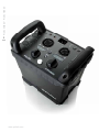
Pro-8a 2400 Air Pro-8a 1200 Air User´s Guide 2 www.profoto.com Pro-8a 2400 Air – Pro-8a 1200 Air Thanks for showing us your confidence by investing in a Pro-8a generator. For more than three decades we have sought the perfect light. What pushes us is our conviction that we can offer even yet better tools for the most demanding photographers. Before our products are shipped we have them pass an extensive and strict testing program. We check that each individual product comply with specified performance, quality and safety. For this reason our flash equipment is widely used in rental studios in Paris, London, New York, and Tokyo and also the most rented flash all over the world. Some photographers can tell just from seeing a picture, if Profoto equipment has been used Professional photographers around the world have come to value Profoto’s expertise in lighting and light-shaping. Our extensive range of Light Shaping Tools offers photographers unlimited possibilities for creating and adjusting their own light. Every single reflector and accessory creates its special light and the unique Profoto focusing system offers you the possibility to create your own light with only a few different reflectors. Enjoy your Profoto product! www.profoto.com Pro-8a 2400 Air – Pro-8a 1200 Air thank you for choosing Profoto 3 Pro-8a 2400 Air – Pro-8a 1200 Air 4 Safety instructions Safety Precautions! Do not operate the equipment before studying the instruction manual and the accompanying safety. Make sure that Profoto Safety Instructions is always accompanied the equipment! Profoto products are intended for professional use! Generator, lamp heads and accessories are only intended for indoor photographic use. Do not place or use the equipment where it can be exposed to moisture, extreme electromagnetic fields or in areas with flammable gases or dust! Do not expose the equipment to dripping or splashing. Do not place any objects filled with liquids, such as vases, on or near the equipment. Do not expose the equipment to hasty temperature changes in humid conditions as this could lead to condensation water in the unit. Do not connect this equipment to flash equipment from other brands. Do not use flash heads without supplied protective glass covers or protective grids. Glass covers shall be changed if it has become visibly damaged to such an extent that their effectiveness is impaired, for example by cracks or deep scratches. Lamps shall be changed if they are damaged or thermally deformed. When placing a lamp into the holder ensure not to touch the bulb with bare hands. Equipment must only be serviced, modified or repaired by authorized and competent service personnel! Warning - The terminals marked with the flash symbol are hazardous live. WARNING – Electrical Shock – High Voltage! Mains powered generator shall always be connected to a mains socket outlet with a protective earthing connection! Only use Profoto extension cables! Do not open or disassemble generator or lamp head! Equipment operates with high voltage. Generator capacitors are electrically charged for a considerable time after being turned off. Do not touch modeling lamp or flash tube when mounting umbrella metal shaft in its reflector hole. Disconnect lamp head cable between generator and lamp head when changing modeling lamp or flash tube! The mains plug or appliance coupler is used as disconnect device. The disconnect device shall remain readily operable. Batteries (battery pack or batteries installed) shall not be exposed to excessive heat such as sunshine, fire or the like. Caution – Burn Hazard – Hot Parts! Do not touch hot parts with bare fingers! Modeling lamps, flash tubes and certain metal parts emit strong heat when used! Do not point modeling lamps or flash tubes too close to persons. All lamps may on rare occasions explode and throw out hot particles! Make sure that rated voltage for modeling lamp corresponds with technical data of user guide regarding power supply! NOTICE – Equipment Overheating Risk Remove transport cap from lamp head before use! Do not obstruct ventilation by placing filters, diffusing materials, etc. over inlets and outlets of the equipment ventilation or directly over glass cover, modeling lamp or flash tube! Note about RF! This equipment makes use of the radio spectrum and emits radio frequency energy. Proper care should be taken when the device is integrated in systems. Make sure that all specifications within this document are followed, especially those concerning operating temperature and supply voltage range. Make sure the device is operated according to local regulations. The frequency spectrum this device is using is shared with other users. Interference can not be ruled out. Final Disposal Equipment contains electrical and electronic components that could be harmful to the environment. Equipment may be returned to Profoto distributors free of charge for recycling according to WEEE. Follow local legal requirements for separate disposal of waste, for instance WEEE directive for electrical and electronic equipment on the European market, when product life has ended! www.profoto.com System description....................................................................................................6 Profoto Air....................................................................................................6 Profoto Air Remote (optional accessory)........................................................6 Profoto Air Sync (optional accessory)............................................................6 Profoto Air USB (optional accessory).............................................................6 Lamp Heads .......................................................................................................7 ProHead.......................................................................................................7 ProTwin.......................................................................................................7 ProRing.......................................................................................................7 ProRing 2 ....................................................................................................8 Functionality .......................................................................................................8 Power supply................................................................................................8 Energy control..............................................................................................8 Modeling light...............................................................................................9 Sync signaling..............................................................................................9 Ready signaling..........................................................................................10 Speed control.............................................................................................10 Ready lamp/Test function...........................................................................11 Flash before ready......................................................................................11 Fan Cooling & Protection System................................................................11 Additional information..............................................................................................12 Color Temperature......................................................................................12 f-stop Stability & Range..............................................................................12 Flash Duration............................................................................................12 Petrol-Electric Generators...........................................................................13 Operating instructions..............................................................................................13 Lamp head connection...............................................................................13 Power connection.......................................................................................13 Settings.....................................................................................................14 Sync via cable............................................................................................14 Sync via Photocell / IR-slave.......................................................................14 Sync via radio (Profoto Air)..........................................................................14 Wireless remote control..............................................................................15 Turn off generator.......................................................................................15 Technical data Profoto Pro-8a 2400 Air....................................................................16 Technical data Profoto Pro-8a 1200 Air....................................................................18 Nomenclature .....................................................................................................20 Quick Guide .....................................................................................................21 www.profoto.com Pro-8a 2400 Air – Pro-8a 1200 Air Table of Contents 5 Pro-8a 2400 Air – Pro-8a 1200 Air 6 System description Pro-8a is designed to be free of compromises. Pro-8a is the fastest, roughest, most versatile and stable generator yet still with the widest power range we ever developed. Pro-8a has a new unique two stage SMPS (Switch Mode Power Supply) recharging circuit making repetition rates faster than ever before. Shoot up to 20 frames per second or 2 per second at 1200Ws. Usage of cameras continues triggering is now practically possible with Pro-8a. Durability of Pro-8a is exceptional to comply with rental and fashion needs plus the greatly increased need of frames taken due to no cost of fi lm with digital cameras. Due to our invention, Profoto PiPE technology (Pre-ignition Plasma Establishing – patent pending). Pro-8a has an extensive wide light power range with exceptional stability of the light energy and color temperature. Safety of the Pro-8a generator is exeptional and complies with the highest demands. Profoto Air Pro-8a is already equipped with the Profoto Air transceiver to prepare for convenient wireless sync and remote control. Profoto Air system is operating on one of eight selectable radio channels on the 2.4 GHz radio frequency band for world wide use. Profoto Air Remote (optional accessory) Complete generator control and sync at your camera or in your hand, including flash energy and modeling light control. Control practically an infinite number of generators in up to six groups, either all at once in Master mode, or in individual groups. Profoto Air Sync (optional accessory) Allows synchronizing of a practically an infinite number of generators, with the same high performance as Profoto Air Remote. Profoto Air USB (optional accessory) An USB 2.0 offers wireless connection of your flash generators to the Profoto Studio Air, a software running on your PC or Mac that gives you full control of your studio flash system. The interface can also be used for updates, extended optional functions and customizations. NOTICE When Pro-8a is remote controlled from a computer, the setting of the four controls (SYNC, MODEL, READY and SPEED) may be overruled by the Profoto Studio 2 program. If any of the controls is computer overruled it will be indicated by four red LCD:s on the generator control panel. For more detailed information, please refer to the Profoto Studio 2 User’s Guide. www.profoto.com Pro-8a is designed for all of the present state-of-the-art Pro heads and light shaping tools. For selected previous models of Profotos lamp heads were is a simple update for compatible fan cooling at 100–120V markets. ProHead The standard heavy-duty flash lamp head is the Profoto ProHead, built for producing flashes with Pro-8a, up to 2400 Ws over and over again, hour after hour. It has an integrated high efficient, long life halogen model-pilot lamp with a switch and a fuse. A thermally controlled 2-speed efficient fan provide silent cooling. For safety reasons thermal protection is built-in. The flashtube and halogen lamp are protected by a diffusing glass cover also serving as a light source corresponding filter and color correction filter. Optional glass cover versions are available. The optimized flash tube is made by high grade UV-free filtered quarts glass and heavy duty electrodes to maximize lifetime. ProTwin When demands are even tougher, the Profoto ProTwin is available with two flash tubes that effectively double the performance. Used with a single generator, it can produce shorter flash durations by splitting half of the power to two flash tubes. Used with two Pro-8a 2400 Air, it can half the recycling speed or double the light energy, up to 4800 Ws. Powered from one of the two connected cables ProTwin has an integrated high efficient halogen model-pilot lamp with a switch and a fuse. A thermally controlled 2-speed efficient fan provides silent cooling. For safety reasons thermal protection is built-in. The flashtube and halogen lamp are protected by a diffusing glass cover also serving as a light source corresponding filter and color correction filter. Optional glass cover versions are available. The optimized flash tube is made by high grade UV-free filtered quarts glass and heavy duty electrodes to maximize lifetime. ProRing If you look for a more lightweight ring flash without modeling light, there’s the Profoto ProRing, with the capacity of up to four 2400 Ws flashes per minute. An entirely mobile source of light, the ring flash fits all Pro-7 generators. The adjustable tripod mount bracket and the wide interior (100 mm diameter) makes the ProRing compatible with all types of cameras as well as most lenses. Optional accessory reflectors expand the ring flash’s capabilities further. www.profoto.com Pro-8a 2400 Air – Pro-8a 1200 Air Lamp Heads 7 Pro-8a 2400 Air – Pro-8a 1200 Air 8 ProRing 2 For fashion or macro photography, when you want a direct and very prominent light, the Profoto ProRing 2 provides a ring flash capable of unlimited flash repetition rate due to built-in thermally controlled silent and efficient fan cooling. The optimized flash tube is made by high grade UV-free filtered quarts glass and heavy duty electrodes to maximize lifetime. A powerful 200 W halogen modeling light are built-in with switch and fuse. Functionality Power supply The Pro-8a generator can be connected to 100–120 VAC or 200–240 VAC, 50–60 Hz. The power supply fuse must not be smaller than specified in the technical data. The generator automatically senses and adapts to the voltage and frequency supplied. Warning Never use ordinary household extension cords to elongate the power cable. They may overheat. Always unwind cord reel extension winders fully before use. Contact your Profoto dealer for proper equipment. Due to the two stage SMPS (Switch Mode Power Supply) technology, the Pro-8a could make a hearable sound during the recharge cycle. This is fully normal and could be seen as the sign of power being charged into the generator. Energy control The selected energy levels for channel A and B are shown in Flash Light Energy Display A [6] and B [17]. The f-stop scale reading is default. To show energy in Ws scale, push and hold the Ws Switch [1]. In f-stop scale, the maximal energy (100%) is shown as 10.0. In Ws scale, the maximal energy (100%) is 2400 for Pro-8a 2400 Air and 1200 for Pro-8a 1200 Air. The maximal energy for channel A is 10.0 (100%) and the maximal energy for channel B 9.0 (50%). The maximal energy in total for the two channels is 100%. Flash Light Energy Control A [8] and Control B [19] are used to adjust the energy levels for channel A and B respectively: • Turn the control clockwise to increase the energy in 1/10 f-stop increments and counterclockwise to decrease. • Press and hold down the control (a “beep” will sound) and turn the control clockwise to increase the energy in 1 f-stop increments and counter-clockwise to decrease. www.profoto.com The Modeling Light Control [7] is used to select one of four modeling light alternatives: • PROP: The modeling light intensity for each lamp head is automatically adjusted to correspond in proportion in-between the generators set energy and maximal energy. • ½ PROP: The modeling light intensity is adjusted automatically in proportion as for PROP when the energy level is changed, but with half modeling light intensity of the designated energy. Half proportional modeling light is used when generators of different sizes are used together; Pro-8a 1200 Air shall be set to ½ PROP and Pro-8a 2400 Air to PROP. • MAX: The modeling lamp gets the maximal intensity, regardless of the flash light energy settings. • MAX PROP: Maximal proportional modeling light is used when maximal light is needed on one channel (the one with highest energy level). The highest set channel will get maximal intensity and the other will correspond proportionally. Therefore the modeling light may change on a channel which is not adjusted. If Pro Studio2 is used to control the generators, a Smart Prop function is available. It is similar to the MAX PROP setting, but the intensity proportions match all lamps and generators. Sync signaling The Pro-8a generator can be synchronized with the camera in different ways; via cable, via Photocell / IR-slave or via the Profoto Air radio system (LPA radio system available on special order). Both systems can not be integrated in the same generator. • The two Sync Connectors [2] allow the camera and a flash meter to be connected simultaneously. The 5 meter sync cable can without restrictions be elongated with a sync extension cable. The bidirectional optical isolated Profoto sync interconnection cable is recommended to be used to prevent ground reference interference when connecting sync cables between different generators. • The Photocell/IR-slave [3] sense signals from most IR sync transmitters as well as from other flash light as a Slave and synchronize the unit. • The Profoto Air remote radio control system is integrated in all Pro-8a generators, meaning that the generators are prepared to be synchronized or controlled either via Air Remote, Air Sync or via the Profoto Studio 2 computer program and Air USB. The Sync Control [5] is used to control the sync signaling: • RADIO: The generator is set to sync via radio. www.profoto.com Pro-8a 2400 Air – Pro-8a 1200 Air Modeling light The Modeling Light Switch [9] is used to turn on/off the modeling light for channel A and B simultaneously. When the modeling light is on, the Modeling Light Switch knob [9] is illuminated. 9 Pro-8a 2400 Air – Pro-8a 1200 Air 10 • SET: Enables setting of radio channel and group. • OFF: The generator is set to sync via cable. • SLAVE: The generator is set to sync via photocell / IR. Ready signaling Ready signaling is used to indicate when the generator is 100% fully charged. The Ready Control [16] is used to select one of four ready signaling alternatives: • OFF: No ready signal. This setting also disables the sound indicating that a switch is pressed or a control is turned. • DIM: The modeling light will be turned off when the generator is being charged, and turned on again when the charging is completed. This setting also disables the sound indicating that a switch is pressed or a control is turned. • BEEP: A clear ”beep” will sound to indicate that the charging of the generator is completed. This setting also enables the sound indicating that a switch is pressed or a control is turned. • BEEP-DIM: The modeling light will be turned off when the generator is being charged, and turned on again when the charging is completed. A clear ”beep” will also sound to indicate that the charging is completed. This setting also enables the sound indicating that a switch is pressed or a control is turned. Speed control The versatile recycling speed settings make it possible to efficiently utilize the mains power supply by adjusting and optimizing the maximum possible speed and load without blowing fuses. The generator’s amperage load from the mains power supply corresponds proportionally to the speed setting. The Speed Control [18] is used to select one of four recycling speed settings: • 25% The slow recycling speed is four times as long as the MAX recycling speed. This alternative shall be selected when the generator is connected to a mains power supply with weak fuses, when you are uncertain as to how well the mains power supply is fused and when weak gas generators are used for charging. It may allow tree or four generators to be connected to the same wall outlet or fuse group. • 50x The fast recycling speed is twice as long as the MAX recycling speed. This setting may allow two generators to be connected to the same wall outlet or fuse group. • 75% The extra fast recycling speed is slightly longer than the extremely fast MAX recycling speed. It reduces load by 25% and may prevent sensitive types of fuses to blow. The recharge speed is anyhow extremely fast compared to other flash generators. • MAX The extreme and fastest recycling speed. Only one Pro-8a can be connected to one wall outlet or fuse group. www.profoto.com Ready lamp [10] is illuminated when the generator is fully charged and ready to flash. Test Button [10] is used to test that all light settings are correct and that the functionally is as expected. When the Test Button [10] is pressed, the generator will flash and the Ready Lamp [10] will turn off while recharging. When the recharge of the generator is completed, the Ready Lamp [10] will be illuminated again. Flash before ready The ”Flash before ready” function makes it possible to flash before the recharging of the generator is ready and fully completed. When a flash is released before the generator is 100% recharged a long ”beep” will sound, indicating an underexposed frame. Naturally the flash light may not correspond fully to the set value. The underexposure of the frame may be so small that it makes no significant difference, however it may be informative to get the feeling of the maximum repetition rate. The underexposure frame may still be usable if the catch of the moment was perfect. Fan Cooling & Protection System The Pro-8a generator is equipped with a very effective fan cooling to prevent over heating. A microprocessor controlling and supervising the system is integrated for protection and safety. Dual fans will normally operate in silent mode but will speed up automatically when working in hot surroundings or continuously at higher power levels. Lower flash energy usage and normal room temperature will slow down the fan speeds to be as silent as possible. If there is risk for overheating of the generator, caused by abnormal external influence, the protective system will automatically protect the generator from damage. The protective system will slow down the recharging intervals and eventually the recharging will stop completely. After a while, when the temperature has decreased sufficiently, the generator will start recharging at a normal pace. This automatic protection will only interfere under extreme conditions such as when the air vents are blocked. The Pro-8a generator is designed to withstand up to 1000 full power flashes during one hour. However it is not advisable to run harder than necessary due to the lifetime of the flash tube. NOTICE The air vents of the generator must never be blocked or covered in any way. Nor should the generator be operated in an enclosed small space. Never store your flash equipment in a car on a hot and sunny day longer than 30 minutes. Avoid storage of the generator close or below the freezing point for more than 30 minutes. A cold generator may not work properly or may even brake and will lose capacity (flash output). There is also a risk of failure because of condensation when a cold generator is moved to a warmer surrounding. Remember that the generator has a great temperature storing mass and will not adapt to the indoor normal surrounding temperature until after 1–3 hours. Never use a Pro-8a generator that has been stored in abnormal temperatures for more than 1 hour. A well insulated case or transport box will prolong the time of storage in abnormal temperature to 2 or 3 hours. Never operate the generator inside a case or transport box due to lack of ventilation. Never expose any flash equipment to wet or humid environments or extreme electromagnetic fields. www.profoto.com Pro-8a 2400 Air – Pro-8a 1200 Air Ready lamp/Test function The ready lamp and test button functions are combined. 11 Pro-8a 2400 Air – Pro-8a 1200 Air 12 Additional information Color Temperature The color temperature of Pro-8a is calibrated to correspond to daylight and, because of the PiPE (patent pending) technology, it remains perfectly constant and reliable from flash to flash and over the entire power range, regardless of the chosen power output and the number of flash heads used. This makes the Pro-8a generators perfectly suited for all kinds of critical assignments, even with high-resolution digital cameras and backs. In combination with all actual Pro flash heads and light shaping tools the Pro-8a generators give neutral and extremely stable color. Please note that other factors, like reflections from surrounding objects and ambient lights with non neutral color characteristic, may influence the light color temperature and spectra. Combining flash tubes and/or glass covers with different coatings can make distinctive color temperature adjustments if needed. f-stop Stability & Range The unique PiPE (patent pending) technology ensures extreme light power stability from flash to flash as well as over the whole power range. The unique wide power range offers maximal flexibility for all situation from light power consuming large objects at large distances to really close ups ex. ProRing2 without overexposure with one and the same flash generator. Please note that influence from ambient and modeling light makes measurement of small power levels difficult. Warning Do not use the light meter’s built-in slave trigger at smaller power levels. Please use a cord and check the shutter speed to avoid ambient light influence. Flash Duration The full power short flash duration has more advantages except from freezing a moving object. It will also make it possible to use a very short camera shutter speed to cut out exposure influence from indoor ambient light as well as direct sunlight. The flash duration can be shortened by reducing the power output with Flash Light Energy Control A [8] and/or B [19]. The shortest flash duration using a ProHead and a Pro-8a generator is 1/12000 sec at energy setting 3,0 - 3,2 (19 - 21,5 Ws). To shorten the flash duration at high power, use a ProTwin head. I.e. if you connect the two plugs of a ProTwin to the Lamp Head Connector A [4] and B [15] of a Pro-8a 2400 Air generator and use both outlets at 1200Ws, the flash duration is just 1/2200s instead of 1/1600s at maximum power with one ProHead. www.profoto.com One dedicated 6000 Watt petrol-electric generator is required to power supply one Pro-8a at MAX speed. To supply one Pro-8a generator at 50% recharge speed setting requires one dedicated 3000W petrol-electric generator. To supply one Pro-8a generator at 25% recharge speed setting requires one dedicated 2000W petrol-electric generator which is the smallest recommended for use with Pro-8a. To supply two Pro-8a generators at 50% recharge speed setting requires one 6000W petrol-electric generator etc. Warning Only use Pro-8a on the same petrol-electric generator, use of any other flash model simultaneously will cause high voltage and may damage the Pro-8a. Pro-8a itself does not cause gas generators to produce high voltages. Underrated power of a petrol-electric generator will cause various bad results. Operating instructions Lamp head connection 1.If only one lamp head is used, connect the lamp to Lamp Head Connector A [4]. 2.When connecting the lamp head plug, align the white dot on the plug with the white dot to the upper left of the Lamp Head Connector. Secure by turning the ring on the plug clockwise. Power connection 1.Use the included power cable to connect the generator to the Power Supply (AC) Connector [11]. 2.The Power Supply Indicator [12] will be red, indicating that the generator is receiving power but is in standby mode. 3.Press the On switch [13]. 4.The Power Sypply Indicator [12] will now be green and the Test Button [10] will be illuminated. www.profoto.com Pro-8a 2400 Air – Pro-8a 1200 Air Petrol-Electric Generators All petrol-electric generators can produce voltage peaks that may damage electronic devices. Pro-8a is however designed to comply with sufficient power rated petrol-electric generators supplying AC-power equal to the voltage and frequency specified and without use of ProGas. 13 Pro-8a 2400 Air – Pro-8a 1200 Air 5. View power in W/s or Relative F-Stops. Press & release Ws button [1] for 5 sec, to toggle flash energy setting. 2 beeps confirm change. 6. 1/10th f-stop flash adjustment. Rotate corresponding control dial clockwise to raise power or counter clockwise to lower. Each click represents 1/10th f-stop. Three quick beeps indicate power can not be raiser or lowered further. 7. Full F-Stop Flash Adjustment. Press down while rotating correspondence control dial clockwise to raise power or counter clockwise to lower. Each click represents 1 f-stop. Three quick beeps indicate power can not be raiser or lowered further. 14 Settings 1.Use the Modeling Light Control [7] to select MAX PROP, MAX, PROP or ½ PROP. Press the Modeling Light switch [9] to turn on the modeling light. 2.Use Flash Light Energy Control A [8] and B [19] to set the energy levels. 3.Use the Ready Control [16] to select BEEP-DIM, BEEP, DIM or OFF. 4.Use the Speed Control [18] to select MAX, 75%, 50% or 25%. Sync via cable 1.Connect a sync cord from the camera to one of the Sync Connectors [2] on the generator. Sync via cable+flash meter 1.Connect a sync cord from the camera to one of the Sync Connectors [2] on the generator. 2.Connect another sync cable from the flash meter to the free Sync Connector [2]. Sync via Photocell / IR-slave 1.Connect an IR transmitter to the camera. 2.Turn the Sync Control [5] to SLAVE. Sync via radio (Profoto Air) 1.Connect an Air Remote or Air Sync unit to the camera. 2.Turn the Sync Control [5] to RADIO. 3.Pro-8a is now ready to flash, with the selected radio channel. www.profoto.com Changing radio channel and group settings: 1.Turn the Sync Control [5] to SET. 2.The radio channel and group setting for the individual lamp head is shown separately in Flash Light Energy Display A [8] or B [19] as a radio channel number (1-8) followed by a group letter (A-F). 3.Turn Flash Light Energy Control A [8] or B [19] clockwise/counter-clockwise to increase/ decrease the radio channel number. 4.Push and turn Flash Light Energy Control A [8] clockwise/counter-clockwise to increase/ decrease the group setting for lamp head A [4]. 5.Push and turn Flash Light Energy Control B [19] clockwise/counter-clockwise to increase/decrease the group setting for lamp head B [15]. 6.Turn the Sync Control [5] to RADIO. Turn off generator 1.The modeling light, energy level, radio channel and group settings are automatically saved as soon as they are changed and will be available at start up. 2.Press the On switch [13] to turn off the power. 3.The Power Supply Indicator [12] will be red, indicating that the generator is receiving power but is in standby mode. 4.Remove the power cable. www.profoto.com Pro-8a 2400 Air – Pro-8a 1200 Air Wireless remote control For Air Remote control, both radio channel and group have to be set. The group can be set individually for each lamp head. For wireless use with Profoto Studio 2 and AIR USB, only radio channel has to be set. 15 Pro-8a 2400 Air – Pro-8a 1200 Air 16 Technical data Profoto Pro-8a 2400 Air General Energy 2400 Ws Energy Distribution Channel A 5–2400Ws 1.0–10.0 Channel B 5–1200Ws 1.0–9.0 Energy Control Range 1.0–10.0 f stop (5–2400 Ws ) Recycling Time 0.05–0.9 s Flash rate at 1.0//4.0//6.0//8.0//10.0 20//15//10//4//1 (flash repetition rate per second at max recharging speed) Flash Duration t0,5 1/12000–1/1600 s Fastest camera shutter speed 2400Ws 1/500 with cable, IR or Profoto Air fast mode. 1/250 with normal Profoto Air Max leaf shutter camera speed Depending of the specific cameras leaf shutters opening and closing time delays Modeling Lamps Total W/Pack (max) 1000 W Modeling Lamps W/Head (max) 500 W Energy Control Increments 1/10 f-stop and full f-stops Energy stability flash to flash +/-1/50 f-stop Color stability flash to flash +/-40 °K Color stability energy range 10.0–5.0 +/-50 °K Color stability energy range 10.0 – 3.0 +/-110 °K Color stability energy range 10.0–1.0 +/-190 °K Guide number @ 2 meters 100ASA with Magnum reflector 128 Specified data conditions A standard ProHead, 120 or 230 V AC Input Power supply 100–127 V / 200–240 V, 50/60 Hz (Nominal) Synchronization and control Sync Socket(s) 2 Lamp Head Socket(s) 2 Wire Sync Compliant to ISO 10330 Standard www.profoto.com 2 (¼ inch phono plug) Photocell/IR-slave and Switch Yes, with automatic sensitivity adjustment USB Interface USB 2.0 Full Speed compatible Wireless sync Yes, Profoto Air (LPA Pocket Wizard inside is available on special order) Wireless Remote Control Yes, Profoto Air (Not available with LPA Pocket wizard) Wireless Radio Range Up to 300 m Computer Control Yes, Profoto Studio via Profoto Air or USB cable Pro-8a 2400 Air – Pro-8a 1200 Air Wire Sync Connectors 17 Miscellaneous Digital Display Yes, f-stop or Ws Fan Cooled Yes, two speed regulated Automatic Multi-Voltage Yes, power supplied worldwide without changing the std head modeling lamp Ready Signal Yes, beep sound and dimming of modeling light during recharge Auto Dumping Yes, can also be dumped manually Speed Control control Yes (100%, 75%, 50%, 25%) See also speed Fuse Requirement per unit at Slow blow fuse 16 A / 230 V, 20 A /110 V Max speed setting Automatic fuse type C,D,E 16 A / 230 V, 20 A / 110 V See also speed control Measurements Dimensions 37x18.5x25 cm; 14.5x7.3x9.8 in Weight 12.2 kg; 26.9 lbs www.profoto.com Pro-8a 2400 Air – Pro-8a 1200 Air 18 Technical data Profoto Pro-8a 1200 Air General Energy 1200 Ws Energy Distribution Channel A 5–1200Ws 2.0–10.0 Channel B 5–600Ws 2.0–9.0 Energy Control Range 2.0–10.0 f stop (5–1200 Ws) Recycling Time 0.05–0.5 s Flash rate at 1.0//4.0//6.0//8.0//10.0 20//17//11//7//2 (flash repetition rate per second at max recharging speed) Flash Duration t0,5 1/12000–1/2200 s Fastest camera shutter speed 2400Ws 1/500 with cable, IR or Profoto Air fast mode. 1/250 with normal Profoto Air Max leaf shutter camera speed Depending of the specific cameras leaf shutters opening and closing time delays Modeling Lamps Total W/Pack (max) 1000 W Modeling Lamps W/Head (max) 500 W Energy Control Increments 1/10 f-stop and full f-stops Energy stability flash to flash +/-1/50 f-stop Color stability flash to flash +/-40 °K Color stability energy range 10.0–6.0 +/-40 °K Color stability energy range 10.0–4.0 +/-80 °K Color stability energy range 10.0–2.0 +/-160 °K Guide number @ 2 meters 100ASA with Magnum reflector 90 Specified data conditions A standard ProHead, 120 or 230 V AC Input Power supply 100–127 V / 200–240 V, 50/60 Hz (Nominal) Synchronization and control Sync Socket(s) 2 Lamp Head Socket(s) 2 Wire Sync Compliant to ISO 10330 Standard www.profoto.com 2 (¼ inch phono plug) Photocell/IR-slave and Switch Yes, with automatic sensitivity adjustment USB Interface USB 2.0 Full Speed compatible Wireless sync Yes, Profoto Air (LPA Pocket Wizard inside is available on special order) Wireless Remote Control Yes, Profoto Air (Not available with LPA Pocket wizard) Wireless Radio Range Up to 300 m Computer Control Yes, Profoto Studio via Profoto Air or USB cable Pro-8a 2400 Air – Pro-8a 1200 Air Wire Sync Connectors 19 Miscellaneous Digital Display Yes, f-stop or Ws Fan Cooled Yes, two speed regulated Automatic Multi-Voltage Yes, power supplied worldwide without changing the std head modeling lamp Ready Signal Yes, beep sound and dimming of modeling light during recharge Auto Dumping Yes, can also be dumped manually Speed Control control Yes (100%, 75%, 50%, 25%) See also speed Fuse Requirement per unit at Slow blow fuse 16 A / 230 V, 20 A /110 V Max speed setting Automatic fuse type C,D,E 16 A / 230 V, 20 A / 110 V See also speed control Measurements Dimensions 34.5x18.5x25 cm; 13.6x7.3x9.8 in Weight 11.4 kg; 25.2 lbs www.profoto.com 1.Ws Switch 2.Sync Connectors 3.Photocell/IR-slave 4.Lamp Head Connector A 5.Sync Control 6.Flash Light Energy Display A 7.Modeling Light Control 8.Flash Light Energy Control A 9.Modeling Light Switch 10. Test Button and Ready Lamp 11. Power supply (AC) Connector 12. Power supply Indicator 13. On Switch 14. USB Connector 15. Lamp Head Connector B 16. Ready Control 17. Flash Light Energy Display B 18. Speed Control 19. Flash Light Energy Control B Nomenclature 7 5 3 8 6 4 2 10 9 1 11 12 11 20 www.profoto.com 19 17 15 14 18 16 Pro-8a 2400 Air – Pro-8a 1200 Air 13 Pro-8a 2400 Air – Pro-8a 1200 Air 21 Quick Guide This Quick Guide refers to the User’s Guide and helps you to quickly get started using the Pro-8a system. If you in any way are unsure of how to use the system, read and follow the safety instructions in the User’s Guide carefully to avoid injuries or damages! Operating instructions Lamp head connections 1. If only one lamp head is used, connect the lamp to the Lamp Head Connector A [4]. 2. When connecting the lamp head plug, align the white dots on the plug with the white dot to the upper left of the Lamp Head Connector. Secure by turning the ring on the plug clockwise. Power connection 1. Use the included power cable to connect the generator to the Power Supply (AC) Connector [11]. 2. The Power Supply Indicator [12] will be red, indicating that the generator is receiving power but is in standby mode. 3. Press the On switch [13]. 4. The Power Supply Indicator [12] will now be green and the Test Button [10] will be illuminated. 5. View power in W/s or Relative F-Stops. Press & release Ws button [1] for 5 sec, to toggle flash energy setting. 2 beeps confirm change. 6. 1/10th f-stop flash adjustment. Rotate corresponding control dial clockwise to raise power or counter clockwise to lower. Each click represents 1/10th f-stop. Three quick beeps indicate power can not be raiser or lowered further. 7. Full F-Stop Flash Adjustment. Press down while rotating correspondence control dial clockwise to raise power or counter clockwise to lower. Each click represents 1 f-stop. Three quick beeps indicate power can not be raiser or lowered further. Settings 1. Use the Modeling Light Control [7] to select MAX PROP, MAX, PROP or ½ PROP. Press the Modeling Light switch [9] to turn on the modeling light. 2. Use Flash Light Energy Control A [8] and B [19] to set the energy levels. 3. Use the Ready Control [16] to select BEEP-DIM, BEEP, DIM or OFF. 4. Use the Speed Control [18] to select MAX, 75 %, 50 % or 25 %. Sync via cable 1. Connect a sync cord from the camera to one of the Sync Connectors [2] on the generator. Sync via cable + flash meter 1. Connect a sync cord from the camera to one of the Sync Connectors [2] on the generator. 2. Connect another sync cable from the flash meter to the free Sync Connector [2]. Sync via Photocell / IR-slave 1. Connect an IR transmitter to the camera. 2. Turn the Sync Control [5] to SLAVE. Sync via radio (Profoto Air) 1. Connect an Air Remote or Air Sync unit to the camera. 2. Turn the Sync Control [5] to RADIO. 3. Pro-8a is now ready to flash, with the selected radio Channel. Wireless remote control For Air Remote control, both radio channel and group have to be set. The group can be set individually for each lamp head. For wireless use with Profoto Studio 2 and AIR USB, only radio channel has to be set. Changing radio channel and group settings: 1. Turn the Sync Control [5] to SET. 2. The radio channel and group setting for the individual lamp head is shown separately in Flash Light Energy Display A [6] or B [17] as a radio channel number (1–8) followed by a group letter (A–F). www.profoto.com 3. Turn Flash Light Energy Control A [8] or B [19] clockwise/ counterclockwise to increase/decrease the radio channel number. 4. Push and turn Flash Light Energy Control A [8] clockwise/ counterclockwise to increase/decrease the group setting for lamp head A [4]. 5. Push and turn Flash Light Energy Control B [19] clockwise/ counterclockwise to increase/decrease the group setting for lamp head B [15]. 6. Turn the Sync Control [5] to RADIO. Turn off generator 1. The modeling light, energy level, radio channel and group settings are automatically saved as soon as they are changed and will be available at start up. 2. Press the On switch [13] to turn off the power. 3. The Power Supply Indicator [12] will be red, indicating that the generator is receiving power but is in standby mode. 4. Remove the Power cable. Lamp Heads Pro-8a is designed for all of the present state-of-the-art ProHeads and light shaping tools. For selected previous models of Profotos lamp heads there is a simple update for compatible fan cooling on 100–120 V markets. ProHead The standard heavy-duty head is the Profoto ProHead, built for producing flashes with Pro-8a, up to 2400 Ws over and over again, hour after hour. It has an integrated high efficient, long life halogen lamp with a switch and a fuse. A thermally controlled 2-speed efficient fan provide silent cooling. For safety reasons thermal protection is built-in. The flash tube and halogen lamp are protected by a diffusing glass cover also serving as a light source corresponding filter and color correction filter. Optional glass cover versions are available. The optimized flash tube is made by high grade UV-free filtered quarts glass and heavy duty electrodes to maximize lifetime. ProTwin When demands are even tougher, the Profoto ProTwin is available with two flash tubes that effectively double the performance. Used with a single generator, it can produce shorter fl ash durations by splitting half of the power to two fl ash tubes. Used with two Pro-8a 2400 Air, it can half the recycling speed or double the light energy, up to 4800 Ws. Powered from one of the two connected cables ProTwin has an integrated high efficient halogen lamp with a switch and a fuse. A thermally controlled 2-speed efficient fan provides silent cooling. For safety reasons thermal protection is built-in. The flashtube and halogen lamp are protected by a diffusing glass cover also serving as a light source corresponding filter and color correction filter. Optional glass cover versions are available. The optimized flash tube is made by high grade UV-free filtered quarts glass and heavy duty electrodes to maximize lifetime. ProRing If you look for a more lightweight ring flash without modeling light, there’s the Profoto ProRing, with the capacity of up to four 2400 Ws flashes per minute. An entirely mobile source of light, the ring flash fits all Pro-7 generators. The adjustable tripod mount bracket and the wide interior (100 mm diameter) makes the ProRing compatible with all types of cameras as well as most lenses. Optional accessory reflectors expand the ring flash’s capabilities further. ProRing 2 For fashion or macro photography, when you want a direct and very prominent light, the Profoto ProRing 2 provides a ring flash capable of unlimited flash repetition rate due to built-in thermally controlled silent and efficient fan cooling. The optimized flash tube is made by high grade UV-free filtered quarts glass and heavy duty electrodes to maximize lifetime. 200 W of powerful halogen modeling light are built-in with switch and fuse. P.O. Box 2023 Profoto AB SE-128 21 Skarpnäck SWEDEN Phone +46 8 447 53 00 [email protected] www.profoto.com 344091-1-320. Printed in Sweden. Technical data and product information are subject to change without notice.