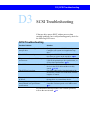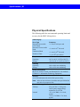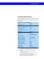
1
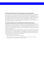
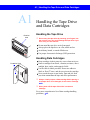
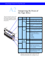
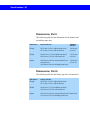
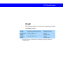
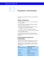
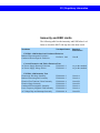
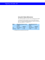
Quantum
SDLT 600
User Reference Guide
User Manual Statements for Class A Equipment (Internal Tape System)
This is a Class A product. This equipment has been tested and found to comply with the limits for a Class A digital
device, pursuant to part 15 of the FCC Rules. These limits are designed to provide reasonable protection against
harmful interference when the equipment is operated in a commercial environment. This equipment generates, uses,
and can radiate radio frequency energy and, if not installed and used in accordance with the instruction manual, may
cause harmful interference to radio communications. Operation of this equipment in a residential area may cause
harmful interference in which case the user will be required to correct the interference at his own expense.
Any modifications to this device—unless expressly approved by the manufacturer—can void the user’s authority to
operate this equipment under Part 15 of the FCC rules.
User Manual Statements for Class B Equipment (Tabletop Tape System)
This equipment has been tested and found to comply with the limits for a Class B digital device, pursuant to Part 15
of the FCC rules. These limits are designed to provide reasonable protection against harmful interference in a residential installation. Any modifications to this device—unless expressly approved by the manufacturer—can void the
user’s authority to operate this equipment under part 15 of the FCC rules. Operation is subject to the following two
conditions: (1) This device may not cause harmful interference, and (2) this device must accept any interference that
may cause undesirable operation.
This equipment generates, uses, and can radiate radio frequency energy and, if not installed and used in accordance
with the instructions, may cause harmful interference to radio communications. However, there is no guarantee that
interference will not occur in a particular installation. If this equipment does cause harmful interference to radio or
television reception, which can be determined by turning the equipment off and on, the user is encouraged to try to
correct the interference by one or more of the following measures:
•
•
•
•
Reorient or relocate the receiving antenna.
Increase the separation between the equipment and receiver.
Connect the equipment into an outlet on a circuit different from that to which the receiver is connected.
Consult the dealer or an experienced radio or TV technician for help.
Contents | SDLT 600 Tape Drive User Reference Guide
Contents
A Using the Tape Drive
A1
A2
A3
A4
Handling the Tape Drive and Data Cartridges
Interpreting the Front of the Tape Drive
Loading and Unloading Data Cartridges
Cleaning the Tape Heads
B Using Data Cartridges
B1
B2
B3
B4
Choosing Data Cartridges
Write-protecting Data Cartridges
Caring for Data Cartridges
Inspecting Data Cartridges
C Connecting the Tape Drive
C1
C2
C3
C4
C5
C6
Understanding the Tape Drive’s Interface
Choosing Cables and Connectors
Setting the SCSI ID
Connecting the SCSI Model as a Single Device
Connecting the SCSI Model in a Daisy Chain
Connecting the Fibre Channel Model
D Troubleshooting Tape Drive Problems
D1
D2
D3
D4
D5
Using the Power-On Self-Test
General Troubleshooting
SCSI Troubleshooting
Checking for Tape Drive Errors
Optimizing the Tape Drive
E Tape Drive Information
E1
E2
Specifications
Regulatory Information
Pointers for Using this Guide
! Pay attention to these points. They are important for tape
drive operation.
A1
Follow these cross references for information on related
topics.
A1 | Handling the Tape Drive and Data Cartridges
A Using the Tape Drive
A1
Receiver
Area
Handling the Tape Drive
and Data Cartridges
Handling the Tape Drive
! Do not carry the tape drive by inserting your fingers into
the receiver area. You could damage the tape drive if you
lift or carry it in this manner.
Do not stand the tape drive on its front panel.
Always place the tape drive on a flat, stable surface.
Avoid dusty, humid, or smoke-filled areas.
Use proper electrostatic discharge (ESD) protection.
Handling Data Cartridges
Protective Case
Keep cartridges in their protective cases when not in use.
Protect cartridges from shock, vibration, moisture, direct
sunlight, dust, smoke, and magnetic fields.
Use the slide-in labels provided. Do not use adhesive
labels or Post-it® notes, and do not write on the cartridge.
Never touch the tape or tape leader. Dust and oils from
your skin contaminate the tape and affect performance.
! Always visually inspect a data cartridge before placing it
in the tape drive. If it is damaged, do not use the cartridge.
B4
! Never power off the tape drive while it contains a
cartridge.
For a more comprehensive list of data cartridge handling
guidelines, B3.
Interpreting the Front of the Tape Drive | A2
A2
This section describes the tape drive
controls as well as tape drive and
data cartridge conditions communicated by the LEDs on the front of
the tape drive.
Interpreting the Front of
the Tape Drive
Title
Color/
Symbol
Action
Explanation
Drive
Density
Orange/
Green
Off
No cartridge is inserted, or an
incompatible cartridge is inserted.
A Super DLTtape™ II cartridge is
inserted or has just been ejected.
A backward-read cartridge, such as
Super DLTtape I or DLTtape™ VS1,
is inserted.
The tape drive is idle. The tape drive
may or may not contain a cartridge.
The tape drive has not been powered
on or is not plugged into a power
source.
The tape drive is in use. This
includes functions such as:
• Loading and unloading tape
• Reading
• Writing
• Rewinding
• Calibrating
Cleaning is required.
Cleaning is not required.
Green
Orange
Drive
Status
Green
On
Off
Flashing
Cleaning
Required
Yellow
On
Off
Eject
N/A
Press
Infrared Port
Note:
Use the Eject button to eject a
cartridge from the tape drive. When
you press Eject, the tape drive
finishes writing data to the tape, then
ejects the cartridge.
The infrared port provides a wireless
remote testing base for customers
and integrators to access system
diagnostic information.
Upon reset, all LEDs flash briefly and then illuminate
in sequence until the tape drive is ready for use. All
LEDs flash when the tape drive encounters an error.
A3 | Loading and Unloading Data Cartridges
A3
Loading and Unloading
Data Cartridges
To Load a Data Cartridge
1. Insert the data cartridge into the receiver on the front of the
tape drive.
2. Push the cartridge completely into the receiver.
The green Drive Status LED ( A2) flashes as the tape loads.
When the tape reaches the Beginning of Tape (BOT) marker,
the Drive Status and Drive Density LEDs ( A2) light
steadily, indicating that the cartridge is ready for use.
Note: The Drive Density LED is green when a
Super DLTtape II cartridge is inserted; orange when a
Super DLTtape I or DLTtape VS1 cartridge is inserted;
and off when no cartridge is inserted or an incompatible
cartridge is inserted ( A2). For information about
choosing data cartridges, B1.
To Unload a Data Cartridge
1. Press the Eject button on the front bezel.
Eject
The tape drive completes writing data to the tape, and the
Drive Status LED ( A2) flashes as the tape rewinds.
When the tape reaches the BOT marker, the tape drive ejects
the data cartridge. The Drive Status LED lights steadily, and
the Drive Density LED:
• Remains green if you ejected a Super DLTtape II cartridge
• Turns off if you ejected a backward-read cartridge.
2. Remove the cartridge from the tape drive and return it to its
plastic case ( A1).
Cleaning the Tape Heads | A4
A4
Cleaning
Required
Cleaning the Tape Heads
Over time, ambient pollution and particulates in the
environment contaminate the tape heads. The tape drive
indicates when cleaning is required by illuminating the
yellow Cleaning Required LED. A2
! Do not clean the tape heads unless the Cleaning Required
LED is illuminated.
! Use ONLY the SDLT CleaningTape. Other cleaning tapes,
such as CleaningTape III or DLT VS CleaningTape, are
incompatible with the SDLT 600 tape drive heads.
To Clean the Tape Heads
1. Insert a Super DLTtape cleaning cartridge (the brand name
to look for is SDLTtape™ CleaningTape) into the tape
drive.
The green Drive Status LED flashes and the cleaning cycle
begins automatically.
When the cleaning cycle completes, the tape drive
automatically ejects the CleaningTape; turns off the Cleaning
Required LED; and steadily illuminates the Drive Status
LED.
2. Remove the CleaningTape, place it back in its plastic case,
and mark the label after each cleaning.
Note: On the last cleaning, the tape drive does not eject the
CleaningTape. Use the Eject button on the front of the
tape drive to eject the expired cleaning cartridge and
dispose of it.
B1 | Choosing Data Cartridges
B Using Data Cartridges
B1
Super DLTtape II Data Cartridge
Choosing Data Cartridges
The SDLT 600 tape drive writes to Super DLTtape II data
cartridges. The Super DLTtape II cartridge is blue and has a
distinctive pattern molded into the plastic, along with the
DLTtape logo. The cartridge’s geometry is similar to
previous DLTtape cartridges to simplify integration with
existing tape library designs. Its keying feature, however,
ensures that it cannot be loaded into previous generation tape
drives.
The SDLT 600 tape drive includes a backward-read
compatibility feature that enables it to read (but not write to)
Super DLTtape I and DLTtape VS1 cartridges. The
following table lists the transfer rates for backward-read
cartridges.
Super DLTtape I Data Cartridge
DLTtape VS1 Data Cartridge
Backward-read Transfer Rates
Cartridge Type
Native
Capacity (GB)
BRC Transfer
Rate: 80% of
Native Read
Transfer Rate
(MB/second)*
Super DLTtape I,
SDLT 320-formatted
Super DLTtape I,
SDLT 220-formatted
DLTtape VS1
160
12.8
110
8.8
80
6.4
* Transfer rates quoted are nominal, measured reading
uncompressed data.
Write-protecting Data Cartridges | B2
B2
Write-protecting Data
Cartridges
To prevent accidental erasure of your data, each data
cartridge has a write-protect switch. When active, this switch
prevents the tape drive from writing data to the cartridge.
! For valuable data, always make sure the cartridge is
write-protected before inserting it into the tape drive.
To enable write-protection:
Move the write-protect switch left so that the bright
orange rectangle is visible.
To disable write-protection:
Move the write-protect switch right so that the orange
rectangle is not visible.
Move switch left to writeprotect media. Orange
indicates write-protected.
B3 | Caring for Data Cartridges
B3
Store data cartridges vertically
in plastic cases.
Use slide-in labels.
Caring for Data
Cartridges
Super DLTtape II data cartridges are engineered to be
reliable, robust, and durable. They are manufactured to
withstand 1,000,000 passes, and have a shelf life of 30 years.
For best results, follow these guidelines for data cartridge
handling and storage:
Follow the handling instructions and observe the
environmental specifications provided in the plastic
cartridge case.
Keep cartridges in their protective cases when not in use.
Protect cartridges from shock, vibration, moisture, direct
sunlight, dust, smoke, and magnetic fields.
Do not stack more than five cartridges on top of each
other.
Store cartridges vertically in protective cases for archival.
Use the slide-in labels provided. Do not use adhesive
labels or Post-it® notes, and do not write on the cartridge.
Do not write on the labels with debris-producing writing
instruments, such as graphite pencils and water-soluble
felt pens. Replace labels instead of erasing them.
Never touch the tape or tape leader. Dust and oils from
your skin contaminate the tape and affect performance.
Avoid unnecessarily opening the cartridge door to prevent
contamination and physical damage.
Inspect data cartridges for damage after dropping them.
B4
Condition cartridges to the recommended normal
operating environment for 24 hours after exposing them
to abnormal temperature or humidity (such as after
transporting the cartridges from one location to another).
! The safety of your data depends on proper care and
handling of cartridges.
Inspecting Data Cartridges | B4
B4
Check reel locks.
Inspecting Data
Cartridges
Improper data cartridge handling is the primary reason for
tape drive problems. To avoid losing data or damaging the
tape drive, inspect cartridges:
Before loading a new cartridge
After dropping a cartridge or subjecting it to physical
shock
When the tape drive becomes inoperable after loading a
cartridge
When you receive a shipment of data cartridges that
shows any sign of shipping damage.
Use the following procedure to inspect a cartridge. If the
cartridge shows any sign of damage, do not use it.
To Inspect a Cartridge
1. Inspect the exterior of the cartridge for physical damage
Inspect spring-loaded hub for
proper tension.
2.
3.
4.
5.
Check for toed-in clips.
6.
7.
(cracks, broken parts) and contamination (sticky or oily
substances, attached debris).
Gently shake the cartridge. Listen for loose pieces.
Check that both reel locks on the cartridge are visible. One
reel lock is located on the end of the cartridge that is
inserted into the tape drive. The other is on the bottom of
the cartridge.
Confirm that the spring-loaded hub on the bottom of the
cartridge is centered. Press the hub to ensure that the spring
is functioning properly and that the hub returns to its normal
position.
Verify that the orange write-protect switch snaps smartly
into position and is not damaged. B2
Open the cartridge door by pressing the tab in the door pivot
notch. Check for possible damage to the tape leader buckle,
including a bent or toed-in appearance or improper seating.
Examine the visible tape leader (without touching it) for
excessive debris, oily or sticky residue, condensed droplets
of moisture, or any other signs of contamination.
Note:
For more detailed and thorough information about
inspecting a data cartridge, refer to the SDLT 600
Product Manual.
C1 | Understanding the Tape Drive’s Interface
C Connecting the Tape Drive
C1
Understanding the Tape
Drive’s Interface
The tabletop model of the SDLT 600 tape drive has an Ultra 160
SCSI interface. The internal model has either a Fibre Channel
interface or an Ultra 160 SCSI interface.
The Ultra 160 SCSI Interface
Ultra 160 provides a low-voltage differential (LVD) mode
running up to 160 MB/second and a single-ended (SE) mode
running up to 40 MB/second.
Note:
The host computer’s SCSI controller card may limit these
speeds. For the best performance, make sure the SCSI
controller card can operate at 160 MB/second.
The tape drive automatically senses the SCSI bus mode and
switches between LVD and SE accordingly. Although the tape
drive defaults to LVD, it switches to SE if the SCSI bus operates
in SE mode. For example, if the SCSI controller card is SE (or
multi-mode set to SE), the tape drive automatically switches to
SE mode. Also, if any device on the SCSI bus is SE, the entire
bus switches to SE, including the tape drive.
In SE mode, the SCSI bus can support up to 7 devices using
cable lengths up to 3 meters. In LVD mode, the SCSI bus can
support up to 15 devices using cable lengths up to 25 meters.
For more information about using the SCSI interface, refer to
the SDLT 600 SCSI Interface Guide.
The Fibre Channel Interface
The Fibre Channel interface runs at speeds up to either
1 Gb/second or 2 Gb/second, depending on the configuration
you choose during installation.
Fibre Channel can support up to 126 devices in a loop
configuration. Longwave transceivers (with fiber optic cable)
support distances up to 10 kilometers; short pulsewave
transceivers (with fiber optic cable) support distances up to 500
meters.
For more information about using the Fibre Channel interface,
refer to the SDLT 600 Fibre Channel Interface Guide.
Choosing Cables and Connectors | C2
C2
Choosing Cables and
Connectors
This section describes the cables and connectors to use with
the SDLT 600 tape drive.
SCSI Cables and Connectors
SCSI versions of the SDLT 600 tape drive have two highdensity 68-pin SCSI connectors. Connect the tape drive to
the host computer using a SCSI cable with the correct type of
connector on each end. The tape drive operates best when the
host computer and host end of the cable have one of the
following types of connector.
SCSI Connectors
High-density 68-pin Micro DB68 or Mini DB68
SCA 80-pin Hot Swap Connector
Very High-density Interconnect Connector
The tape drive will, however, operate with other host-end
connectors.
Fibre Channel Cables and Connectors
Fiber Optic Cable
Fibre Channel versions of the SDLT 600 tape drive
(internal model only) have one Fibre Channel port. The Fibre
Channel port is equipped with a Small Form-factor,
Pluggable (SFP) converter for connecting the fiber optic
cable. You may have to supply the SFP for the other end of
the cable; some host bus adapters have the transceiver
already built in to the adapter, in which case, you do not have
to supply the SFP for the other end of the cable.
Note:
Both ends of the cable require a transceiver.
C3 | Setting the SCSI ID
C3
3
3
Setting the SCSI ID
This section describes how to set the SCSI ID on the tabletop
tape drive. For information about setting the SCSI ID on an
internal tape drive, refer to the SDLT 600 Product Manual.
Each device connected to a SCSI bus must have a unique
SCSI ID number. The factory preset SCSI ID is 3 for the
tabletop tape drive and 5 for the internal tape drive. Ensure
that your tape drive’s SCSI ID is unique on your SCSI bus.
You can change the SCSI ID using the push-button switch on
the back of the tape drive. Use the point of a pencil to press
the buttons above or below the number display to increase or
decrease the ID number.
! If the tape drive is the only SCSI device, leave the SCSI ID
set to 3, the default setting.
! Do not use a SCSI ID of 7. This setting is typically
reserved for the SCSI controller.
Connecting the SCSI Model as a Single Device | C4
C4
Connecting the SCSI
Model as a Single Device
The SDLT 600 tape drive performs best when it is the only
device connected to the SCSI bus. If the SDLT 600 tape
drive is the only SCSI device you intend to connect to the
SCSI bus, follow these steps:
1. Make sure the host computer and all peripheral devices
are powered off.
Terminate upper
SCSI port.
! Never connect the tape drive while the host system or
peripheral devices are powered on.
2. Connect a terminator to the upper SCSI connector on the
back of the tape drive.
3
! You must terminate the SCSI bus. The SCSI controller
terminates one end, while a terminator on the tape drive
terminates the other end.
3. Connect one end of the SCSI cable to the lower
connector on the back of the tape drive.
4. Connect the other end of the SCSI cable to the SCSI
connector on the host computer.
For more information about connecting the SDLT 600 tape
drive, refer to the SDLT 600 Product Manual.
C5 | Connecting the SCSI Model in a Daisy Chain
C5
Connecting the SCSI
Model in a Daisy Chain
If you are adding your SDLT 600 tape drive to a SCSI daisy
chain, follow these steps:
Terminate upper
SCSI port.
1. Ensure that all devices have unique SCSI IDs.
C3
2. Make sure the host computer and all peripheral devices
are powered off.
! Never connect the tape drive while the host system or
peripheral devices are powered on.
3
3. Connect the SCSI cable from the host computer to the
lower SCSI connector on the back of the tape drive.
4. Continue the SCSI chain using the upper SCSI
connector.
3
5. If the SDLT 600 tape drive is the last device in the
chain, connect a terminator to the upper SCSI connector.
! You must terminate the SCSI bus. The SCSI controller
terminates one end, while a terminator on the last device
in the chain terminates the other end.
For more information about connecting the SDLT 600 tape
drive, refer to the SDLT 600 Product Manual.
Connecting the Fibre Channel Model | C6
C6
Connecting the Fibre
Channel Model
The Fibre Channel protocol and the SCSI protocol rely on
different methods of addressing devices. Unlike the SCSI
protocol, which uses fixed SCSI IDs, the Fibre Channel
protocol uses different addressing depending on the type of
topology used for the network: point-to-point, arbitrated
loop, or fabric. The addresses are set dynamically (in real
time) at the time the device attaches to the network.
Follow these steps to connect a Fibre Channel SDLT 600
tape drive:
1. Insert a fiber optic cable into the Fibre Channel port on
the back of the tape drive.
The connector is fully seated when it snaps into the port.
! You can connect a Fibre Channel connector while the tape
drive is still powered on; this capability is known as “hotswappable” or hot-pluggable.”
2. Optional step (for this step, rely on your judgement
based on your knowledge of the host bus adapter that
you are currently using): Attach an SFP connector
( C2) to the other end of the fiber optic cable before
connecting it to the host device.
For more information about connecting a Fibre Channel tape
drive, refer to the SDLT 600 Product Manual.
D1 | Using the Power-On Self-Test
D Troubleshooting Tape Drive Problems
D1
Using the Power-On
Self-Test
The SDLT 600 tape drive performs a self-diagnostic test,
called a Power-On Self-Test (POST), each time you power it
on. This test helps you detect problems with your tape drive.
POST completes in approximately 10 seconds. While POST
is in progress, the tape drive responds BUSY to SCSI
commands.
If the host computer attempts to negotiate synchronous or
wide transfers, the tape drive negotiates to asynchronous or
narrow. It may take longer than the duration of POST for the
tape drive to become ready.
During POST, each LED lights in sequence.When POST is
complete, the green Drive Status LED lights steadily.
If the tape drive fails POST, check for the following possible
problems:
There is no cartridge in the tape drive.
The tape drive is not receiving adequate power (try a new
cord or different outlet).
The tape drive is not properly connected to the host
computer and other SCSI devices.
If any of these problems exist, correct the problem, power
off the tape drive and power it back on to restart POST. If
none of these problems exists or the tape drive fails POST
after you have corrected them, refer to additional
troubleshooting information in the SDLT 600 Product
Manual available on the product CD-ROM.
! Do not attempt to open the tape drive enclosure. Only a
qualified Quantum technician should perform service.
General Troubleshooting | D2
D2
General Troubleshooting
Troubleshoot problems with your SDLT 600 tape drive using
the following steps:
1. Visually inspect the cartridge for damage, and try a new
cartridge if necessary. B4
2. Make sure the cables and connectors are in good
condition. For example, check that they are not worn
or broken, and there are no missing or bent pins.
3. Make sure the connector on each end of the cable is fully
seated.
4. Disconnect the tape drive from the host system, power
off the tape drive, and power it on again to perform a
POST.
D1
5. If you have a SCSI tape drive, remove all devices from
the SCSI bus. Connect the tape drive directly to the host
computer and terminate it ( C4). Confirm that the tape
drive and host computer are communicating properly
before adding other devices.
6. If you have a Fibre Channel tape drive, look at the back
panel to see if the green LED (the “link light”) there is
illuminated ( C6). If the link light is illuminated, you
have a working connection with the Fibre Channel
network.
7. Ensure that your operating system (modules, patches,
and drivers), backup software, and tape drive are
compatible. Visit www.quantum.com/sdlt for the most
current compatibility information.
If you cannot identify or correct the problem, call Quantum
Technical Support at 1-888-827-3378. Have your model and
serial number available when you call. Find these numbers
on the bottom of the tape drive.
D3 | SCSI Troubleshooting
D3
SCSI Troubleshooting
If the tape drive passes POST with no power or data
cartridge problems, but is still performing poorly, check for
the following SCSI issues.
SCSI Troubleshooting
Possible Problem
Solution
Your system is not configured to “see”
the tape drive.
Check your system and SCSI bus settings.
Configure your system to recognize the tape
drive.
The SCSI ID is not unique.
Change the SCSI ID. The new ID takes effect the
next time you power on the tape drive. C3
The parameters for your SCSI adapter
Check your SCSI controller card. Ensure that it is
are incorrect.
LVD for the optimal tape drive performance, or
SE for slower performance. C1
The SCSI bus is not terminated correctly. Confirm that a terminator is installed on the last
device in the SCSI chain and that it is fully
seated. C4, C5
The SCSI bus is too long.
For single-ended mode, limit the length of the
SCSI bus to 3 meters. For LVD mode, limit the
length to 25 meters.
Too many devices are connected to the
Limit the number of external devices. Try using
SCSI bus.
the tape drive as a stand-alone device.
The tape drive is operating more slowly For the best performance, make sure your SCSI
than indicated in its performance
controller card can operate at 160 MB/second.
specifications.
C1
For information about possible Fibre Channel problems,
refer to the next section. D4.
Checking for Tape Drive Errors | D4
D4
Checking for Tape Drive
Errors
The SDLT 600 tape drive (SCSI version) provides status and
event information about the SCSI controller, devices, data
transfer, and errors. The Fibre Channel version of the tape
drive also indicates whether a signal is present and provides
the Fibre Channel address, speed, topology, and node and
port information.
You can use iTalk to access this information through the tape
drive’s infrared port located on the front of the tape drive.
You can find iTalk on the CD-ROM that accompanies the
tape drive, or you can download it from
www.quantum.com/sdlt
(you must first register your tape drive on the web site). See
iTalk’s online help for information about using the software.
D5 | Optimizing the Tape Drive
D5
Optimizing the Tape
Drive
Many factors contribute to SDLT 600 tape drive
performance. Host system considerations include processor
speed, block size, SCSI adapter performance, bus
configurations, and software.
If you are concerned about the performance of your
SDLT 600 tape drive, check the following:
1. Ensure that your tape drive is properly defined for the
host system. If the tape drive is not defined within the
system, the SCSI adapter does not interact well with the
tape drive.
2. Make sure your controller card and the SCSI bus are
operating in LVD. If the controller card or the SCSI bus
are operating in SE, the tape drive switches to SE.
3. De-fragment your hard disk on a regular basis.
Fragmented disks and files take much longer to back up.
4. Check your host block size. The SDLT 600 tape drive
supports block sizes up to 16 MB. In general, the larger
the block size, the better the throughput. Many older
software applications default to a 512-byte block size,
which results in poor performance.
5. Make sure you are using a data cartridge that is
compatible with the tape drive.
B1
E1 | Specifications
E Tape Drive Information
E1
Specifications
This section lists maximum data transfer rates, physical
specifications, functional specifications, dimensions, and
weight for the SDLT 600 tape drive.
Maximum Data Transfer Rate
The following table shows the maximum and burst data
transfer rates for the SDLT 600 tape drive.
Configuration
Native
Compressed*
Burst Max†
SCSI Ultra 160 (LVD mode)
SCSI Ultra 160 (MSE LVD mode)
SCSI Ultra 160 (SE mode)
Fibre Channel (1 Gb/s)
Fibre Channel (2 Gb/s)
36 MB/sec
36 MB/sec
36 MB/sec
36 MB/sec
36 MB/sec
72 MB/sec
72 MB/sec
40 MB/sec
72 MB/sec
72 MB/sec
160 MB/sec
160 MB/sec
40 MB/sec
100 MB/sec
200 MB/sec
* The compression rates shown assume an industry standard 2:1 compression ratio.
Actual compression ratios achieved depend on the redundancy of data files being
recorded.
† Burst speeds are limited by the SCSI bus itself, or by the Fibre Channel transceiver, not
the design of the SDLT 600 tape drive or the Super DLTtape II data cartridge.
Specifications | E1
Physical Specifications
The following table lists environmental operating limits and
accuracy for the SDLT 600 tape drive.
Data Integrity
Error Type
Frequency
Detected, Recoverable
(ECC) Read
Detected, Unrecoverable
Read
Undetected Read
< 1 error in 106 bytes read
Rewrite of Data
< 1 per 106 bytes written
< 1 error in 1017 bits read
< 1 error in 1027 bits read
Temperature
Operating
Storage
10 °C to 40 °C (50 °F to 104 °F)
-40 °C to 66 °C (-40 °F to 150 °F)
Humidity
Operating
Storage
20% to 80% non-condensing
10% to 95% non-condensing
Safety Certifications
Meets UL 60950, GS mark, and EN60950/IEC 950 standards
(EN60825-1: Information Technology Equipment)
Air Flow
10.4 CFM minimum with 0.09 in H2O pressure drop
Note: Allow at least 100 mm of unobstructed space behind the
tape drive for proper air flow.
Electrical Rating (numbers describe the Ultra 160 model)
Tabletop
Internal
85 to 264 VAC, 63 W typical,
100 W (power supply rating)
maximum, 47 to 63 Hz
+5V, 4.9 A RMS, 6.2 A Peak,
typical
+12V, 0.7 A RMS, 2.7 A Peak,
typical
E1 | Specifications
Functional Specifications
The following table lists capacity and life expectancy for the
SuperDLTtape II cartridge, as well as tape drive performance
characteristics.
Super DLTtape II Cartridge Capacity
Native
Compressed (2:1)
300 GB
600 GB
Super DLTtape II Life Expectancy
Cartridge load/unload cycles*
5,000
Media insertions†
20,000
Full media uses (end-to-end)‡
250
Media passes**
1,000,000
Tape Drive Performance Characteristics
Load to BOT
Unload from BOT
Average access time
Maximum access time
Average rewind time
Maximum rewind time
Read/write tape speed
Rewind tape speed
Linear search tape speed
Linear density
Track density
Number of tracks
18 s (typical),
63 s (unformatted tape)
19 s
79 s (from BOT)
190 s (from BOT)
77 s
156 s
108 ips
160 ips
160 ips
233 Kbpi
1502 tpi
640 physical tracks
* A load/unload cycle is when the the data cartridge is inserted
into the receiver, loaded to BOT, calibrated, and then
unloaded.
† An insertion is when a data cartridge is inserted into the
receiver and then unloaded.
‡ A full media use is an operation that reads or writes (with
verify off) the full capacity of the data cartridge.
** A media pass occurs with any movement (in either direction)
of the surface of the media over the tape head.
Specifications | E1
Dimensions, Part I
The following table lists the dimensions for the internal and
the tabletop tape drive.
Dimension
Internal Version
Tabletop
Version
Height
82.55 mm (3.25 in.) without front bezel;
85.73 mm (3.38 in.) with front bezel
164.46 mm
(6.48 in.)
Width
146.05 mm (5.75 in.) behind front bezel;
148.59 mm (5.85 in.) with front bezel
174.75 mm
(6.88 in.)
Depth
203.20 mm (8.00 in.) measured from back
of front bezel;
215.40 mm (8.48 in.) including front bezel
320.04 mm
(12.60 in.)
Dimensions, Part II
The following table lists the library tape drive’s dimensions.
Dimension
Library Version
Height
82.55 mm (3.25 in.) without front bezel;
85.73 mm (3.38 in.) with front bezel
Width
146.05 mm (5.75 in.) behind front bezel;
148.59 mm (5.85 in.) with front bezel
Depth
203.20 mm (8.00 in.) measured from back of front bezel;
212.22 mm (8.36 in.) including front bezel
E1 | Specifications
Weight
The following table lists the tape drive’s unpackaged weight
and shipping weight.
Weight*
Internal and Library Version
Tabletop Version
Unpackaged
Weight
Shipping
Weight
2.38 kg (5 lbs 4 oz)
6.27 kg
(13 lbs 13 oz)
9.90 kg
(21 lbs 13 oz)
3.77 kg (8 lbs 5 oz)
* Weights depend on configuration. The packaging used may change the
shipping weight.
Regulatory Information | E2
E2
Regulatory Information
This section lists regulatory information for the SDLT 600
tape drive.
Safety Certifications
The SDLT 600 tape drive meets or exceeds the following
safety requirements:
UL 60950 (USA): Information Technology Including
Electrical Business Equipment
EN60950/IEC 950 (Europe): Information Technology
Including Electrical Business Equipment
• EN60825-1 Information Technology Equipment
The SDLT 600 tape drive is certified to bear the GS mark and
TUV identification markings.
The SDLT 600 tape drive is a Class I laser product that
complies with 21 CFR 1040.10 as applicable on the date of
manufacture.
Electromagnetic Interference
Certifications
The internal version of the SDLT 600 tape drive complies
with FCC Class A limits in a standard enclosure. The
tabletop tape drive complies with FCC Class B limits. The
following table lists Electromagnetic Interference (EMI)
certifications.
Type
Regulation/Certification
EEC Directive 89/336 CE
EN55022 (EU)
EN55024 (EU)
FCC Rules Part 15B Class B
(MDOC)
Canada
VCCI Class B (Japan)
BSMI Class A (Taiwan)
Australia/New Zealand
CFR 47, 1995
IECS-003
V-3/97.04
CNS 13438
AS/NZS 3548
E2 | Regulatory Information
Immunity and ESD Limits
The following table lists the immunity and ESD failure level
limits to which the SDLT 600 tape drive has been tested.
Test Name
Test Specification
EN55022: 1998 Radiated and Conducted Emissions
Radiated Electromagnetic Emissions
EN55022: 1998
Conducted Electromagnetic Emissions
Required
Performance
Class B
Current Harmonics and Flicker Emissions Tests
AC Power Supply Harmonic Emissions
EN61000-3-2
AC Power Supply Voltage Flicker
EN61000-3-3
As per the standard
As per the standard
EN55024: 1998 Immunity Tests
Electrostatic Discharge Immunity
Radiated Electromagnetic Immunity
Electrical Fast Transient / Burst Immunity
Electrical Surge Immunity
Conducted Electromagnetic Immunity
Power Frequency Magnetic Field Immunity
AC Voltage Dips and Interrupts Immunity
Criteria A
Criteria A
Criteria B
Criteria B
Criteria A
Criteria A
Criteria B
EN61000-4-2
EN61000-4-3
EN61000-4-4
EN61000-4-5
EN61000-4-6
EN61000-4-8
EN61000-4-11
Regulatory Information | E2
Acoustic Noise Emissions
The following table lists acoustic noise emission levels, both
as noise power and sound pressure, for the SDLT 600 tape
drive. The table provides the preliminary declared values per
ISO 9296 and ISO 7779/EN27779.
Mode
Idle
Streaming
Noise Power Emission Level
(LNPEc)
Sound Pressure Level
(LPAc)*
Internal
Tabletop
Internal
Tabletop
Not applicable
5.9 Bel
5.4 Bel
5.9 Bel
Not applicable
47 dB
42 dB
53 dB
* Sound pressure level measured at front of drive.
Copyright
Copyright © 2004 by Quantum Corporation. All rights reserved.
Document Origination: Boulder, Colorado, USA.
Trademarks
Quantum, the Quantum logo, and the DLTtape logo are trademarks of
Quantum Corporation, registered in the U.S.A. and other countries. DLTtape,
DLTSage, Value DLTtape, and Super DLTtape are trademarks of Quantum
Corporation.
Other company and product names used in this document are trademarks,
registered trademarks, or service marks of their respective owners.
Legal Disclaimers
The information contained in this document is the exclusive property of
Quantum Corporation. Quantum retains its copyright on the information
contained herein in all cases and situations of usage, including derivative
works.
The possessor agrees to safeguard this information and to maintain it in
confidence and not re-publish it in whole or in part without Quantum’s prior
written consent.
Quantum reserves the right to make changes and improvements to its products,
without incurring any obligation to incorporate such changes or improvements
in units previously sold or shipped.
It is the responsibility of the user to carefully read and understand the User
Manual statements for Class A Equipment and Class B Equipment that appear
on the inside of the front cover.
Contact Information
Telephone numbers and street addresses change frequently; for the latest,
up-to-date contact information, visit www.quantum.com .
Telephone numbers, street addresses, time zones, and other pertinent facts are
listed in the Support section of the web site.
February 2004
Quantum Publication Number: 81-81220-01 REV A02
81-81220-01 A02