1
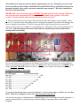
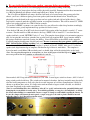
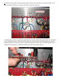
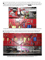
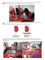
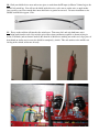
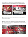
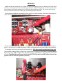
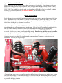
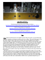
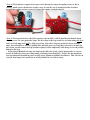
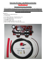
Zero Loss FX Loop™ installation instructions
loop Revision 3A
Read all instructions before doing anything!
Before beginning actual loop installation, you must discharge your filter caps and unplug the amp
from the wall! Your amp should be in good working order, problem free. Install loop solely at your
own risk, if you are not qualified to work around high voltage electronics, do not do so. High voltage
can be deadly, proceed at your own risk!
Packing list:
- Loop board preassembled and tested.
- 2.5’ shielded wire
- 3” heat shrink tubing large, 2”small (color may vary)
- Two 4” 22 gauge wire pieces (color/s may vary).
- 1 ground lug with hardware.
- 1 small DPDT toggle switch
- Various decoupling resistors (2 watt) 4.7K-75K
- 4.7K(4.3K), 5.6K, 8.2K(7.5K) 2 watt metal oxide resistor.
Please think twice about any desire to mod an original amp in any way. Ultimately up to you as the
owner, but with great kits readily available like the excellent Metro line up, and high resale prices for
untouched originals, there really is no need to mod older amps anymore. This loop is intended for
these kits and original builds.
IMPORTANT!: these instructions apply to FX REV 3A boards only! For other revisions (1B-2B), be
sure to use the correct instructions for your loop board/kit found in the appendix . The board
revision is clearly marked in white text atop the board near the send jack.
1: The power for the loop board is tapped directly from the amp’s the PI (phase inverter) supply*, and in
this case, a 2 watt metal oxide decoupling resistor is strung directly from the loop board to the PI supply line
turret to simplify the installation. You need to measure the B+ at the PI supply point, measure the DC
voltage at the turret below in a 100 watt, or at the PI filter cap. This turret is where your decoupling resistor
will attach.. You must measure this turret with all tubes in, amp fully powered up. Do this before
starting install and carefully.
Now use the chart below to determine the decoupling resistor value you need to use. Also note if you have
and use a dual tap power transformer (or variac), you must choose this resistor based on your HIGH voltage
setting, no variac: DO NOT omit this resistor or use improper (too small) value, damage could result!
Decoupling (Dropping) resistor chart:
B+ at PI supply:
2 watt resistor needed
440-423V------------------------------------------------------ 75K
422-402V ------------------------------------------------- 68K
401-386V -------------------------------------------- 56K
385-366V --------------------------------------- 47K
365-345V ---------------------------------- 33K
344-326V ----------------------------- 22K
325-305V ------------------------ 10K
304- 280V ------------------ 4.7K
* Loop may be fed directly from screen node alternately, in lower voltage amps (overall B+ at or less than
440V). Chart above still applies just the same, and you will just omit step 15.
- See note 1 for more info on calculating the decoupling/dropping resistor value at the end of these instructions. A
loop B+ of around 300V is a good general target to aim for, though a range from 250V to around 320V is
acceptable.
2: Be sure to discharge filter caps, unplug amp now before proceeding! A very good idea
to remove tubes now as well to avoid damaging them while physically working on the amp.
Next thing to do is to locate where the loop will be physically installed. Demonstrated for these instructions
is a 100 watt Marshall style Master volume amp built from a Metro ’69 style kit.
For 45 or 50 watt Marshall style amps, the board will need to be located nearer the preamp end of the
chassis, you’ll use a different spacing over from speaker jack from that shown below. Basically just
physically center the board in the open space between last speaker jack and side/end of the chassis. Once
loop board is centered, mark the send hole location, use template from there. This will be around 2.5” SEND
jack to last speaker jack hole in a JTM 45 kit for example.
If you have a PPIMV, resonance, etc control in the way, you will need to adjust loop location accordingly.
Use common sense, poorly implemented loop position can lead to issues.
Now back to 100 watt ‘69 or MV style chassis install: Jack spacing of the loop board is exactly 1.5” center
to center. For this install in a 100 watt chassis, the loop “SEND” hole is located 3.5” over from the last
speaker jack hole, second “RETURN” hole is 5” over. The template shown below is for orientation purposes
only, do not print this one below, print the line or pedal level loop template PDF , doesn’t matter which at
this point as both have same hole spacing for drilling. You will find links to these PDFs in the appendix.
Your drill template should come out clear and exact. Be sure to measure that your printer actually prints
100% full size before drilling anything! Jack center to center spacing should be 1.5”, overall template
dimensions are 3.5“ x 2.5“.Once the loop template is printed, just locate “SEND” hole over 3.5“ from last
speaker jack, align bottom edge of template with bottom edge of chassis, mark holes. The template is
devised around a stock Metro 100 watt back panel, so should align well with existing holes on the back:
-Note: You can print this template on a transparency or clear sticker paper to label the loop nicely after drilling, be
sure to use pedal or line level template as appropriate for your kit.
Once marked, drill 2 loop jack holes carefully to 7/16” inch. Locate bypass switch as shown , drill ¼“ hole if
using switch provided with loop. The switch can be mounted elsewhere, but keep in mind it must physically
clear the board components as well as be placed to avoid long runs or lead dress complications. Located as
shown, no problems have arisen. If a longer wire run from board to bypass switch is needed, use shielded
wire from loop board to the switch connections.
-Note, be careful drilling! Easy for a drill bit to “take off” or “grab” and run in too far, potentially hitting and
damaging the circuit board or nearby wires. To avoid this possibility, a scrap piece of wood/plastic, etc inside
the chassis when drilling is recommended. Can use a couple C clamps or such to hold it against the chassis. To
be sure the clamps will not mar the outer panel, a couple scrap pieces of wood or plastic should be inserted
under the clamp’s “feet” that will rest on the panel.
3: Drill 1/8” hole in chassis and install ground lug as shown, exact location is not critical but that‘s by V3
there, the PI tube. Hardware assembly is bolt-chassis-lug-lock washer-nut:
Tempting and possible to just add this ground lug to the preamp socket bolt already nearby, but a dedicated
lug is a safer/better practice. Hold loop board in position so you can mark the black ground wire (already
attached to board) to easily reach your new ground lug with some slack to spare. Clip black ground wire to
length and remove approx ½ “insulation from the end, but do not solder to lug yet:
4: Now grab your decoupling resistor determined from the chart above, slide a piece of insulation over the
resistor lead to be connected to the board, route lead roughly as shown, solder resistor from top of board
through hole marked “B+”. Be careful not to burn the electrolytic cap with your iron while doing so!:
Trim excess resistor lead from top of board.
Note here that some 2 watt resistors are physically larger than others, size may vary, so adjust for good fit
between loop board and PI turret as needed here.
“helpings hands” make this bit easier:
5: Now fit the loop board in place, screw in jacks to hold in place temporarily. With board in place, slip a
scrap piece of insulation on the other free decoupling resistor leg now, make sure the resistor has enough lead
length to connect easily to the turret, roughly trim lead if needed, but DO NOT solder this connection yet as
the board will be freed to attach a couple more wires soon:
-In amps that need a longer run for the PI supply to loop board, see note 2 at the end of these instructions.
6: Need to tap the signal now. Completely remove the wire from the treble pot wiper (middle lug) to the
main board PI input cap (or from treble pot middle lug to the master volume pot lug in a 2203/4 master
volume style amp).
7: Strip insulation from one end of the 4” pieces of wire now, to solder to the board “IN” and “OUT” holes
on your board. Solder these in place from bottom of board, then route straight up for now:
8: Use a scrap piece of resistor lead or wire to make a little jumper for the switch now. It just connects two
side by side switch lugs together as shown below, solder in place on switch.
9: At this point go ahead and solder your ground wire to the ground lug now. Then screw in jacks and
switch final (note switch orientation -jumper towards loop board), and solder your decoupling resistor to the
PI supply turret.
10: Grab your shielded wire now and cut one piece to reach from the PI input (or Master Volume lug) to the
middle left switch lug. You will use the shield inside this wire, so be sure to cut the wire a couple inches
long overall so you leave enough bare inner shield wire to ground on one end. Cut outer insulation to size.
Should look like this approx so far:
11: Focus on the end that will attach to the switch now. Trim away foil, and strip both inner wire’s
insulation back from the ends a bit, twist the pair of these inner conductors together as shown in first pic
below. Fold back (and cut down if needed) the short bit of shield wire sticking out on this end, slip a piece of
heat shrink on (make sure it covers the shield bit completely), shrink. This end attaches to the middle row
left lug of the switch, solder now if ready:
For the other end of this wire, strip and twist inner pair of wires together the same, these wires will be
soldered to the PI input (or Master Volume left pot lug in a 2203/4 amp). The shield wire was left long on
this end, shield wire will be grounded/soldered to the back of the treble pot or ground buss, clip excess
shield as needed, but do not solder this end yet.
12: Now cut your second shielded wire to size, exactly as above, but this one runs from the treble pot wiper
(middle lug) to the right middle row switch lug. Hook up in the same manner as the first shielded wire,
solder the switch end only at this time.
13: Now slip 2 or 3 pieces of approx 1” long larger diameter heat shrink over the shielded wires together,
these pieces will hold the shielded wires together/add support along their run. Adjust their spacing and
shrink. If you wish you can just use zip ties instead. Now solder shielded wires fully on both ends, shields to
ground once satisfied with routing and fit.
14: Route the “IN” wire as shown to top right switch lug, cut to length, solder. Repeat for “OUT” wire,
solder to top left switch lug:
15: Now last step is to swap out the 8.2K circled below (in series with the 10K) with the 4.7K metal oxide
resistor provided. This is necessary to compensate for the extra bit of current the loop draws through these
resistors, and keep the amp operating as it was. This is not always absolutely necessary, as voltages will only
be lower in the PI and preamp as a result, but the intent is not to effect the original tone, so swap that 8.2K
resistor for the 4.7K.
- If your amp has a two 2 watt 10K’s in series here, swap out one 10K with a 5.6K 2 watt metal oxide
resistor instead.
- If your amp had only a single 10K here, there will not be as much voltage change, so can leave as is, or can
swap the 10K for an 8.2K resistor to get about right back to where you started concerning voltages
throughout the amp.
- If your amp has a single 8.2K 2 watt resistor here, swap with 7.5K 2 watt resistor if desired though nothing
really need be done.
-Omit this step if your loop is alternately fed from the screen supply node.
TESTING:
Double check your connections now. Make sure the B+ decoupling resistor is connected well to the board
and turret, no stray bit of resistor lead sticking out under the board to things below, no shorts anywhere else
in your wiring, and that the ground wire is soldered to the ground lug securely. Be sure no stray exposed
wires below the loop board are reaching up and touching loop board bottom.
Test the board grounding by measuring as below, meter set to read resistance, black meter lead clipped to
chassis. Touch red probe to unused pad labeled “GND“:
If you read 0 ohms/shorted (some meters will display .1 ohms or so, that’s fine) , the ground connection is
good. If you read open or a higher resistance, recheck your ground wire and solder joint to the ground lug.
If the above checks out, you can get ready to power up. ALL tubes must be installed in the amp now.
Amp should be running in high voltage mode (if applicable), no variac. Set your meter to read DC volts in a
high voltage range (400V or higher). Clip black meter probe to ground/chassis, clip or hold red meter probe
as shown (if holding the probe, keep your free hand OUT of the chassis and OFF of the chassis or any
ground, stick it in your back pocket if you must !):
Again all tubes need to be in the amp, turn on amp, let it warm up in standby, set volume controls off.
When warmed up, turn off standby (again to high voltage mode if applicable). Watch the meter to be sure
the DC Volt reading (ideally) stays around 285-310V, no higher than 330V. If the meter reads at or above
330V, shut amp off, check your decoupling resistor value and loop ground. If you read in a range from about
320V - 330V, you should go up in value with your decoupling resistor. If the loop B+ reading is good after
watching (or periodically checking), for at least 5 minutes, you are finished testing.
LEVEL ADJUSTMENT
Level adjustment is preset initially, but different amps/circuits may require a one-time fine tuning of the loop
level. Only may need to do this if there is a notable and undesirable rise or fall in the amp’s overall volume
(or overdrive in a cranked amp) when switching the loop in or out. Do allow amp/loop to fully warm up a
while before deciding if any adjustment is warranted.
See the small trimmer pot below . REV 3A boards have a top adjustable square shaped trimmer pot here
instead, but otherwise adjustments are made just the same. You will need to be extremely careful in the live
amp, use a small insulated screwdriver (other hand behind the back) to adjust this pot. Be sure the
screwdriver or your hand does not contact anything inside the live amp! VERY SLIGHTLY adjust the pot
as needed, a few degrees at most should be more than enough. Do not set the pot fully one way or another,
only very slight tweaks if any will be needed here. Easiest to have someone play the amp while another
adjusts the trimmer pot until, loop in or bypassed, there is no volume/gain change in either switch position.
Adjust pot clockwise to reduce loop signal strength, counterclockwise to increase, again using very tiny
adjustments. Once set you are good to go.
-----------------------------------------------------------------------------------------------------------------------------------------------------------------------------------------------
Congratulations, enjoy your new loop! Do remember the Send jack will be nearest the speaker jacks, Return
jack nearest the preamp, in a Marshall style amp, so as to avoid confusion when inserting effects if you do
not label your loop. Review note 3 at the end of these instructions to be sure your loop is never subjected to
a potentially damaging situation.
Appendix and Notes:
Instructions for previous board revisions 1B-2B are found here:
http://home.comcast.net/%7Ejbjdav26/Loop%20instructions%20Rev%201B%20to%202B.pdf
Pedal level loop template can be found here:
http://home.comcast.net/%7Ejbjdav26/Loop%20Template%20Pedal.pdf
Line level loop template can be found here:
http://home.comcast.net/%7Ejbjdav26/Loop%20Template%20Line.pdf
Notes
-Note 1: The loop board B+ must not exceed 400V (capacitor rating) at any time, a good operating range
is 290-310V, but plenty of headroom is available at even lower voltages. The loop will draw approx 1.7ma
on average (.0017A) so can use Ohm’s law to calculate a more exact decoupling resistor if desired.
Ohm’s law is V=IR. V= Volts (voltage drop here), I=current in Amps, and R= resistance in Ohms. So say
your B+ at the PI supply is 346V. You want the loop to run at 300V, so you take your 346V reading and
subtract 300V to get 46V. This is our “V” for the equation above. We know I averages about = .0017A.
Now we just want to find R, the decoupling resistor value. Rearranging the formula gives us R=V/I.
Plugging in the numbers we have R= 46/.0017 =27,058 Ohms, or 27.06K. So 27K is the desired
decoupling resistor. Current may vary a bit from board to board but this should get you very close every
time. Can just follow the chart above of course, but there’s the theory for those who want it. A 2 watt
Metal oxide resistor should be used for long term stability/low noise though actual wattage demands may
be much lower.
Once the loop board is in, more current is going through the dropping/decoupling resistors preceding
the PI. This results in a bit lower preamp/PI voltages which you may like, may not, may not notice. To get
voltages back where they were, the B+ line resistors preceding the PI need to be tweaked as in step 15
above. In a Super Lead you will have a 10K and 8.2K (commonly) in series before the PI, and roughly
swapping the 8.2K out for a 4.7K resistor will put voltages back where they were pre loop install. This side
note is just for those that want to understand why a board resistor is (optionally) changed in step 15.
-Note 2: The board has a support hole to pass a wire through for longer decoupling resistor to B+ in
routing. Attach wire as shown below in those cases, be sure the wire is insulated and the elsewhere
mounted decoupling resistor is secure if a longer B+ routing is indeed required:
-Note 3: The loop boards have a B+ filter capacitor rated at 400V or 450V, much higher than the board
should ever see. In some particular setups, the B+ voltage to the loop could rise over that rating only if no
tubes are in the amp at all and it is fully powered up. Since these loops are meant for known working
amps, there should be no reason to pull all tubes and fully power up, but if that ever needs to be done for
any reason, just disconnect the loop board decoupling resistor temporarily while doing so to avoid possibly
damaging the loop.
In any typical Marshall style amp, the loop board will be fine if only a single preamp tube or even two
need to be pulled for some reason temporarily (with amp powered up fully). Just be sure the amp has at
least 1 preamp tube installed any time you fully power up and no problems should arise. This won’t be an
issue for most amps, but is noted here to avoid problems in cases where it may.