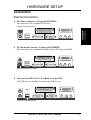
1
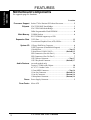
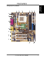
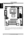
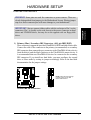
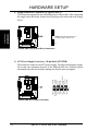
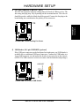
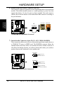
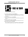
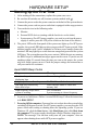
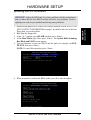
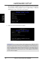
E760
®
CUV4X-CME
PC133 AGP-4X Motherboard
USER’S MANUAL
Product Name:
ASUS CUV4X-CME
Manual Revision: 1.02 E760
Release Date:
April 2001
FEATURES
FEATURES
Motherboard Parts
Motherboard Components
See opposite page for locations.
Location
Processor Support Socket 370 for Pentium III/Celeron Processors ....................... 2
Chipsets VIA VT82C694X North Bridge ............................................... 1
VIA VT82C686B South Bridge ................................................ 9
2Mbit Programmable Flash EEPROM ..................................... 8
Main Memory 2 DIMM Sockets ...................................................................... 4
PC133 SDRAM support up to 1GB
Expansion Slots 3 PCI Slots .............................................................................. 12
1 Accelerated Graphics Port (AGP) 4X Slot .......................... 13
System I/O 1 Floppy Disk Drive Connector ............................................... 6
2 IDE Connectors (UltraDMA66 Support) .............................. 5
1 Parallel Port ............................................................... (Top) 15
2 Serial Ports (COM1/COM 2) .............................. (Bottom) 15
USB Connectors (Port 0 & Port 1) ........................................ 16
USB Connectors (Port 2 & Port 3) .......................................... 7
1 PS/2 Mouse Connector .............................................. (Top) 17
1 PS/2 Keyboard Connector ................................... (Bottom) 17
Audio Features (on audio models only)
Creative CT5880 Audio Chipset ............................................ 10
AC’97 V2.1 Audio Codec ...................................................... 11
1 Game/MIDI Connector .............................................. (Top) 14
1 Line Out Connector ............................................. (Bottom) 14
1 Line In Connector ................................................ (Bottom) 14
1 Microphone Connector ........................................ (Bottom) 14
Power Power Supply Connector .......................................................... 3
Form Factor Micro ATX
2
CUV4X-CME User’s Manual
FEATURES
1
2
3
4
5
FEATURES
Motherboard Parts
Component Locations
6
17
16
15
14
13
12
11
10
9
CUV4X-CME User’s Manual
87
3
FEATURES
FEATURES
Motehrboard Layout
Motherboard Layout
19.2cm (7.56in)
CPU_FAN
ATX Power Connector
PS/2
T: Mouse
B: Keyboard
VIA
GAME_AUDIO
VGA
VT82C694X
Chipset
Line
Out
Line
In
2 3
4 5
CD
AUX
MODEM
Mic
In
Accelerated Graphics Port
PWRLED
HDLED
CLRTC
Flash EEPROM
(Programable BIOS)
PCI 1
Audio
Codec
CREATIVE
CT5880
PCI 2
CUV4X-CME
PCI 3
VIA
VT82C686B
Chipset
PWR
RESET
USBPORT
IR
NOTE: The Creative CT5880 audio chipset, external GAME/AUDIO
connectors, and internal audio connectors are optional components, and
present in audio models only. The components are grayed in the above
motherboard layout.
4
CUV4X-CME User’s Manual
24.4cm (9.6in)
Socket 370
FLOPPY
PARALLEL PORT
COM1
Secondary
IDE
USB1
USB2
DIMM Socket 2 (64/72-bit, 168-pin module)
Primary IDE
Bottom:
DIMM Socket 1 (64/72-bit, 168-pin module)
CR2032 3V
Lithium Cell
CMOS Power
HARDWARE SETUP
Connectors
External Connectors
1) PS/2 Mouse Connector (Green 6-pin PS2KBMS)
This connector is for a standard PS/2 mouse.
H/W SETUP
Connectors
PS/2 Mouse (6-pin Female)
2) PS/2 Keyboard Connector (Purple 6-pin PS2KBMS)
This connector is for a standard keyboard using an PS/2 plug (mini DIN).
PS/2 Keyboard (6-pin Female)
3) Universal Serial BUS Ports 1 & 2 (Black two 4-pin USB)
Two USB ports are available for connecting USB devices.
USB 1
Universal Serial Bus (USB) 2
ASUS CUV4X-CME User’s Manual
5
HARDWARE SETUP
4) Serial Port Connectors (Teal/Turquoise 9-pin COM1 / 9-pin COM2)
Two serial ports are available for pointing devices or other serial devices.
H/W SETUP
Connectors
COM1
COM2
Serial Ports (9-pin Male)
5) Parallel Port Connector (Burgundy 25-pin PRINTER)
A parallel port is available for a parallel printer.
Parallel Port (25-pin Female)
6) Game/MIDI Connector (Gold 15-pin GAME_AUDIO) (optional)
This connector supports a joystick or a game pad for playing games, and MIDI
devices for playing or editing audio files.
Game/MIDI (15-pin Female)
7) Audio Connectors (Three 1/8” AUDIO) (optional)
The Line Out (lime) connects a headphone or speakers. The Line In (light blue)
connects a tape players or other audio sources. The Mic (pink) connects a
microphone.
Line Out Line In Mic
1/8" Stereo Audio Connectors
6
ASUS CUV4X-CME User’s Manual
HARDWARE SETUP
Internal Connectors
WARNING! Some pins are used for connectors or power sources. These are
clearly distinguished from jumpers in the Motherboard Layout. Placing jumper
caps over these connector pins will cause damage to your motherboard.
H/W SETUP
Connectors
IMPORTANT: Always connect ribbon cables with the red stripe to Pin 1 on the
connectors. Pin 1 is usually on the side closest to the power connector on hard
drives and CD-ROM drives, but may be on the opposite side on floppy disk
drives.
Primary IDE Connector
Secondary IDE Connector
1) Primary (Blue) / Secondary IDE Connectors (40-1 pin IDE1/IDE2)
These connectors support the provided UltraDMA/66 IDE hard disk ribbon cable.
Connect the cable’s blue connector to the primary (recommended) or secondary
IDE connector, then connect the gray connector to the UltraDMA/66 slave device
(hard disk drive) and the black connector to the UltraDMA/66 master device. It
is recommended that non-UltraDMA/66 devices be connected to the secondary
IDE connector. If you install two hard disks, you must configure the second
drive to Slave mode by setting its jumper accordingly. Refer to the hard disk
documentation for the jumper settings.
CUV4X-CME
CUV4X-CME IDE Connectors
NOTE: Orient the red markings
(usually zigzag) on the IDE
ribbon cable to PIN 1.
PIN 1
ASUS CUV4X-CME User’s Manual
7
HARDWARE SETUP
2) Floppy Disk Drive Connector (34-1 pin FLOPPY)
This connector supports the provided floppy drive ribbon cable. After connecting
the single end to the board, connect the two plugs on the other end to the floppy
drives.
H/W SETUP
Connectors
NOTE: Orient the red markings on
the floppy ribbon cable to PIN 1
PIN 1
CUV4X-CME
CUV4X-CME Floppy Disk Drive Connector
+12.0 Volts
+5V Standby
Power Good
Ground
+5.0 Volts
Ground
+5.0 Volts
Ground
+3.3 Volts
+3.3 Volts
+5.0 Volts
+5.0 Volts
-5.0 Volts
Ground
Ground
Ground
Power Supply On
Ground
-12.0 Volts
+3.3 Volts
3) ATX Power Supply Connector (20-pin block ATXPWR)
This connector connects to an ATX power supply. The plug from the power supply
fits in only one orientation because of the different hole sizes. Find the proper
orientation and push down firmly making sure that the pins are aligned.
CUV4X-CME
CUV4X-CME ATX Power Connector
8
ASUS CUV4X-CME User’s Manual
HARDWARE SETUP
4) CPU Fan Connector (3-pin CPU_FAN)
The CPU fan connector supports cooling fans of 350mA (4.2 Watts) or less. The
fan wiring and plug may vary depending on the fan manufacturer. The red wire
should be positive while the black should be ground. Connect the fan plug to the
board taking into consideration the polarity of the connector.
GND
+12V
NC
H/W SETUP
Connectors
CPU_FAN
CUV4X-CME
CUV4X-CME 12-Volt Cooling Fan Power
5) USB Header (10-1 pin USBPORT) (optional)
If the USB port connectors on the back panel are inadequate, one USB header is
available for two additional USB port connectors. Connect the USB header to a
2-port USB connector set and mount the bracket to an open slot on the chassis.
(NOTE: The USB connector set does not come with the motherboard package.)
GND
GND
P2+
P2USB PWR
USBPORT
5
6
10
USB PWR
P3P3+
GND
GND
CUV4X-CME
1
CUV4X-CME Front Panel USB Header
ASUS CUV4X-CME User’s Manual
9
HARDWARE SETUP
6) Standard Infrared Module Connector (5-pin IR)
This connector supports an optional wireless transmitting and receiving infrared
module. The infrared module mounts to a small opening on system cases that
support this feature. Use the five pins as shown in Back View and connect a
ribbon cable from the module to the motherboard SIR connector according to
the pin definitions.
H/W SETUP
Connectors
Front View
Back View
+5V
(NC)
IRRX
GND
IRTX
IR
1
+5V
(NC)
IRTX
GND
IRRX
CUV4X-CME
CUV4X-CME Infrared Module Connector
7) Internal Audio Connectors (4-pin CD_IN, AUX, VIDEO, MODEM)
These connectors allow you to receive stereo audio input from sound sources as
a CD-ROM, TV tuner, or MPEG card. The MODEM connector allows the
onboard audio to interface with a voice modem card with a similar connector. It
also allows the sharing of mono_in (such as a phone) and a mono_out (such as a
speaker) between the audio and a voice modem card.
CD (White)
Left Audio Channel
Ground
Right Audio Channel
AUX (Black)
Left Audio Channel
Ground
Right Audio Channel
MODEM
CUV4X-CME
Modem-In (to Modem)
Ground
Modem-Out (from Modem)
CUV4X-CME Internal Audio Connectors
10
ASUS CUV4X-CME User’s Manual
HARDWARE SETUP
The following PANEL illustration is for items 8-11.
HD LED
+PLED
-PLED
+HDLED
-HDLED
PWR
Ground
Reset
Ground
ATX Power Switch*
Reset SW
H/W SETUP
Connectors
Power LED
* Requires an ATX power supply.
CUV4X-CME
CUV4X-CME System Panel Connectors
8) System Power LED Connector(2-pin PWRLED)
This 3-1 pin connector connects to the system power LED. The LED lights up
when you turn on the system power, and blinks when the system is in sleep or
soft-off mode.
9) Hard Disk LED Connector (2-pin HDLED)
This 2-pin connector is for the hard disk LED. This LED blinks during hard disk
operation.
10) ATX Power Switch Connector (2-pin PWR)
The system power is controlled by a momentary switch attached to this connector.
11) Reset Switch Connector (2-pin RESET)
This 2-pin connector connects to the case-mounted reset switch for rebooting
the system without turning off the power switch. This is a preferred method
ASUS CUV4X-CME User’s Manual
11
HARDWARE SETUP
Starting Up the First Time
1.
2.
3.
4.
5.
H/W SETUP
Up
Connectors
Powering
After making all the connections, replace the system case cover.
Be sure that all switches are off (in some systems, marked with ).
Connect the power cord to the power connector at the back of the system chassis.
Connect the power cord to a power outlet that is equipped with a surge protector.
Turn on the devices in the following order:
a. Monitor
b. External SCSI devices (starting with the last device on the chain)
c. System power (For ATX power supplies, you need to switch on the power
supply as well as press the ATX power switch on the front of the chassis.)
6. The power LED on the front panel of the system case lights up. For ATX power
supplies, the system LED lights up when you press the ATX power switch. If the
monitor complies with “green” standards or if it has a power standby feature,the
monitor LED may light up or switch between orange and green after the system
LED does. The system then runs the power-on tests. While the tests are running,
the BIOS beeps or additional messages appear on the screen. If you do not see
anything within 30 seconds from the time you turn on the power, the system
may have failed a power-on test. Check the jumper settings and connections or
call your retailer for assistance.
Award BIOS Beep Codes
Beep
One short beep when
displaying logo
Long beeps in an endless loop
One long beep followed by
three short beeps
High frequency beeps when
system is working
Meaning
No error during POST
No DRAM installed or detected
Video card not found or video card
memory bad
CPU overheated
System running at a lower frequency
7. At power on, hold down <Delete> to enter BIOS Setup. Follow the instructions
in 4. BIOS SETUP.
* Powering Off the computer: You must first exit or shut down the system before
switching off the power switch. For ATX power supplies, you can press the ATX
power switch after exiting or shutting down the operating system. If you use
Windows 9X, click the Start button, click Shut Down, then click Shut down
the computer? The power supply should turn off after Windows shuts down.
NOTE: The message “You can now safely turn off your computer” does not
appear when shutting down with ATX power supplies.
12
ASUS CUV4X-CME User’s Manual
HARDWARE SETUP
Managing and Updating Your BIOS
Upon First Use of the Computer System
H/W SETUP
Connectors
It is recommended that you save a copy of the original motherboard BIOS along
with a Flash Memory Writer utility (AFLASH.EXE) to a bootable floppy disk in
case you need to reinstall the BIOS later. AFLASH.EXE is a Flash Memory Writer
utility that updates the BIOS by uploading a new BIOS file to the programmable
flash ROM on the motherboard. This file works only in DOS mode. To determine
the BIOS version of your motherboard, check the last four numbers of the code
displayed on the upper left-hand corner of your screen during bootup. Larger numbers
represent a newer BIOS file.
1. Type FORMAT A:/S at the DOS prompt to create a bootable system disk. DO
NOT copy AUTOEXEC.BAT and CONFIG.SYS to the disk.
2. Type COPY D:\AFLASH\AFLASH.EXE A:\ (assuming D is your CD-ROM
drive) to copy AFLASH.EXE to the boot disk you created.
NOTE: AFLASH works only in DOS mode. It does not work in the DOS prompt
within Windows and does not work with certain memory drivers that may be
loaded when you boot from the hard drive. It is recommended that you reboot
using a floppy disk.
3. Reboot the computer from the floppy disk.
NOTE: BIOS setup must specify “Floppy” as the first item in the boot sequence.
4. In DOS mode, type A:\AFLASH <Enter> to run AFLASH.
IMPORTANT! If the word “unknown” appears after Flash Memory:, the
memory chip is either not programmable or is not supported by the ACPI BIOS
and therefore, cannot be programmed by the Flash Memory Writer utility.
ASUS CUV4X-CME User’s Manual
13
HARDWARE SETUP
5. Select 1. Save Current BIOS to File from the Main menu and press <Enter>.
The Save Current BIOS To File screen appears.
SETUP
H/W SETUP
BIOS
BIOS
Connectors
Updating
6. Type a filename and the path, for example, A:\XXX-XX.XXX and then press
<Enter>.
14
ASUS CUV4X-CME User’s Manual
HARDWARE SETUP
Updating BIOS Procedures
WARNING! Update the BIOS only if you have problems with the motherboard
and you know that the new BIOS revision will solve your problems. Careless
updating can result in your motherboard having more problems!
BIOS
H/W SETUP
SETUP
Updating
Connectors
BIOS
1. Download an updated ASUS BIOS file from the Internet (WWW or FTP) (see
ASUS CONTACT INFORMATION on page 3 for details) and save to the boot
floppy disk you created earlier.
2. Boot from the floppy disk.
3. At the “A:\” prompt, type AFLASH and then press <Enter>.
4. At the Main Menu, type 2 then press <Enter>. The Update BIOS Including
Boot Block and ESCD screen appears.
5. Type the filename of your new BIOS and the path, for example, A:\XXXXX.XXX, then press <Enter>.
NOTE: To cancel this operation, press <Enter>.
6. When prompted to confirm the BIOS update, press Y to start the update.
ASUS CUV4X-CME User’s Manual
15
HARDWARE SETUP
7. The utility starts to program the new BIOS information into the Flash ROM.
The boot block is updated automatically only when necessary. This minimizes
the possibilities of boot problems in case of update failures. When the
programming is done, Flashed Successfully appears.
SETUP
H/W SETUP
BIOS
BIOS
Connectors
Updating
8. Follow the onscreen instructions to continue.
WARNING! If you encounter problems while updating the new BIOS, DO NOT
turn off the system because this may cause boot problems. Just repeat the process,
and if the problem still persists, load the original BIOS file you saved to the boot
disk. If the Flash Memory Writer utility is not able to successfully update a
complete BIOS file, the system may not boot. If this happens, call the ASUS
service center for support.
16
ASUS CUV4X-CME User’s Manual