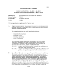
1
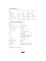
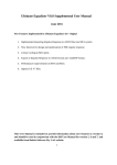
C10ps C12ps HT10ps HT12ps owner's manual analog and digital systems 2 table of contents introduction . . . . . . . . . . . . . . . . . . . . . . . . . . . . . . . . . . . . . . . . . . . . . . . . . . . . .3 cautions . . . . . . . . . . . . . . . . . . . . . . . . . . . . . . . . . . . . . . . . . . . . . . . . . . . . . . . .3 about the a/d/s/ subwoofers . . . . . . . . . . . . . . . . . . . . . . . . . . . . . . . . . . . . . . . . .5 unpacking . . . . . . . . . . . . . . . . . . . . . . . . . . . . . . . . . . . . . . . . . . . . . . . . . . . . . .5 placement . . . . . . . . . . . . . . . . . . . . . . . . . . . . . . . . . . . . . . . . . . . . . . . . . . . . . .6 system connection . . . . . . . . . . . . . . . . . . . . . . . . . . . . . . . . . . . . . . . . . . . . . . . .7 power connection and power switch operation . . . . . . . . . . . . . . . . . . . . . . . . . .8 controls and connections . . . . . . . . . . . . . . . . . . . . . . . . . . . . . . . . . . . . . . . . . . .9 maintenance . . . . . . . . . . . . . . . . . . . . . . . . . . . . . . . . . . . . . . . . . . . . . . . . . . .12 voltage conversion . . . . . . . . . . . . . . . . . . . . . . . . . . . . . . . . . . . . . . . . . . . . . . .12 in case of difficulty . . . . . . . . . . . . . . . . . . . . . . . . . . . . . . . . . . . . . . . . . . . . . . .12 typical wiring diagrams . . . . . . . . . . . . . . . . . . . . . . . . . . . . . . . . . . . . . . . . . . .14 specifications . . . . . . . . . . . . . . . . . . . . . . . . . . . . . . . . . . . . . . . . . . . . . . . . . . .18 common specifications . . . . . . . . . . . . . . . . . . . . . . . . . . . . . . . . . . . . . . . . . . . .18 introduction Congratulations, and thank you for purchasing an a/d/s/ powered subwoofer. The culmination of years of acoustic research, these subwoofers are designed to flawlessly reproduce the lowest octaves of music and to add incredible impact and realism to movie soundtracks, while perfectly complimenting a/d/s C-series and H-series loudspeakers. Please read this manual carefully to fully understand and maximize the performance of your a/d/s system, and to enjoy years of superb musical and home theater sound reproduction. Be sure to save your sales receipt. It is your best record of the date of purchase, which is required for warranty service. Read and follow all cautions, warnings and notes. cautions WARNING To reduce the risk of electric shock, do not remove any parts of the speaker. There are no user serviceable parts inside. If service is required have it performed by a qualified service professional. WARNING To help prevent electric shock, connect the speaker using the power cable into properly grounded electrical outlets. These cables are equipped with 3-prong plugs to help ensure proper grounding. Do not use adapter plugs or remove the grounding prong from a cable. WARNING To help prevent fire or shock hazard, do not expose the speakers to rain or submerge in water. The speakers should be situated away from heat sources such as radiators, heat registers, stoves or other heat sources. Be sure all the components in the system are turned off while making audio and power connections. 3 4 about the a/d/s/ subwoofers This manual covers four a/d/s/ powered subwoofer models. The C10ps and the C12ps use 10 and 12-inch subwoofers in sealed enclosures. The HT10ps and the HT12ps also use 10 and 12-inch drivers respectively, and feature precision-tuned bandpass enclosures for enhanced low-frequency performance. The C-series subwoofers have an attractive black matte finish that blends well into most decors. The HT-series subwoofers feature a black wood grain furniture grade finish. These subwoofers are designed to be used with in-wall, bookshelf, or miniature satellite loudspeakers, extending the bass response of the system by an octave or more. The crossovers in the subwoofers can relieve the satellite speakers of the demand of reproducing the deep bass portion of the sound range. The combination of an a/d/s/ subwoofer and high-quality full range speakers produces a system that has the bass response and output level of much larger loudspeakers, in a compact, easy to place format. The subwoofers can be driven by either preamp level or speaker level input signals. They can be connected to nearly any audio system. The amplifiers in these subwoofers are capable of producing very high peak current levels. Sophisticated protection circuitry protects the amplifier and woofer if the subwoofer is operated in a manner that might cause damage. In addition, the amplifiers feature an array of controls that make it easy to adjust the subwoofer so it integrates seamlessly with the main speakers in the system. The HT-series a/d/s/ subwoofer cabinets have a sophisticated tuned bandpass design. The speaker in the cabinet is mounted between two chambers. One chamber is sealed. The other is vented through special high flow tuned vents to the rear of the cabinet. This computer optimized hybrid design gives the transient response of a simple sealed box system with the efficiency and power handling of a vented box design. The result is clean and dynamic bass at all listening levels. The speakers in the a/d/s/ subwoofers have an oxygen-free copper wire voice coil wound on a Kapton former for maximum efficiency and fidelity. The cones are acoustically inert and capable of moving large volumes of air without flexing or bending. unpacking These subwoofers are fairly heavy. Rather than lifting the unit out of the shipping carton, turn the open carton over and lift it off of the subwoofer. Set the carton on a carpeted floor (or a large pad) with the top up and open. Hold the top flaps down against the outside of the carton. Carefully tip the carton onto its side and then onto the open top of the carton. Hold the inner packing material in place while turning the carton over to prevent the subwoofer from slipping out of the carton. Lift the carton off of the subwoofer. Remove the inner packing material. Then gently turn the subwoofer over onto the base. Save the shipping carton and inner packing material for future use. Moving or shipping the subwoofer in anything other than the factory carton can result in costly damage, which is not covered by the warranty. 5 placement Unlike higher frequency sound, our ears have difficulty locating the source of deep bass sound. Consequently, you have a fair amount of flexibility in where you place the subwoofer in your listening room. We recommend placing the subwoofer at the same end of the room as the main speakers. Avoid placing the subwoofer close to the main listening area or behind it. The HT-series Subwoofer should be placed so its back is at least three inches away from the wall behind it and all adjacent furniture a drapery. This is necessary for three reasons. First, it allows the bass sound coming out of the ports to spread freely into the room. Second, it allows the amplifier to radiate the heat generated by normal operation. Third, it allows clearance for the cable connected to the subwoofer. Included with the C-series subwoofers are a set of four spiked feet. Using these spiked feet will stabilize the subwoofer placement and may tighten up the subwoofer's sound. There are threaded inserts in the bottom of the cabinet for these spiked feet. The sound quality of your a/d/s/ subwoofer and how its sound blends with the main speakers is affected by its location in the room and the settings of the rear panel controls. The bass output level of the subwoofer is greatly affected by its placement in the room. As a general rule the level will increase as the subwoofer is moved closer to the boundaries (the walls and corners) of the room. Corner placement will produce the strongest bass and in some instances the smoothest response. Experiment with a variety of placements that are practical and domestically acceptable. Try adjusting the settings of the subwoofer phase and subwoofer volume controls in each room location you try. The goal is a combination of placement and control settings that produces smooth solid bass that blends seamlessly with the main speakers. One trick for achieving the desired bass performance in a given room is to locate the subwoofer at your normal seating/listening location. Then walk around the room while the system is playing. Look for a spot in the room that is suitable for the subwoofer and where the bass sounds the best to you. If you then place the subwoofer at that location, the bass response at your normal seating position will be the same. Another consideration when selecting a location for the subwoofer is required audio signal and power wiring connections. Because long cable runs can degrade a sound signal, the subwoofer should not be too far away from the other components of the system. Plan for routing the connecting cables where they won't be stepped on or crushed. The powerful bass sound energy produce by the a/d/s/ subwoofers can cause objects to vibrate or rattle. Setting a compact disc player on the subwoofer may result in tracking problems or data errors. Purely electronic equipment, such as amplifiers or receivers are not likely to be affected by the subwoofer. Never set up a turntable near the subwoofer. This can produce severe acoustic feedback. 6 system connection There are two ways the subwoofer can be connected to the other components in the system. If the electronics in the system consists of a separate preamp and power amp or integrated electronics that have preamp/power amp jumpers, use the low level (preamp level) inputs and outputs of the subwoofer (See below). Low-level connection: In this configuration the subwoofer is connected to the system between the preamp and power amp sections of the electronics. Connect the preamp outputs to the low level inputs on the subwoofer with shielded RCA cables. This supplies the subwoofer with a full range signal. Use the same type of cable to connect the high pass outputs of the subwoofer to the power amp inputs of the system electronics. This returns the portion of the signal above the very low frequency range to the main amplifier and satellite speakers. High-level connection: In this configuration the subwoofer is connected to the system between the amplifier outputs and the satellite speakers. The signal that drives the subwoofer amplifier is derived from this signal. Use the same speaker wire that goes to the satellite speakers for this connection. If your amplifier has remote or B speaker outputs you can use those instead. Connect the speaker outputs of the amplifier to the inputs of the high level connection of the subwoofer with conventional two-conductor speaker wire. Be sure to keep the left/right channel connections correct. Also be sure the phasing of the connections (the positive/negative orientation of the connections) is consistent throughout the system. The left and right channel outputs from the amplifier should be connected to the appropriate high-level inputs on the subwoofer. Of greater importance is the phasing or positive/negative orientation of the connections. It is very important that the positive (+) terminals of the amplifier are connected to the positive terminals of the high level inputs of both channels of the subwoofer. Similarly, the negative (-) terminals of the amplifier must be connected to the negative terminals of the high level inputs of both channels of the subwoofer. All speaker wire is marked in some way to make it easy to trace the two conductors. There may be a rib or a stripe on the insulation of one conductor or the insulation may be clear with copper and silver colored conductors. Decide which conductor will be used for the positive connections and which for the negative connections. Then be sure all the amplifier-to-subwoofer connections are consistent. 7 power connection and power switch operation Note: Read and follow all of the cautions, warnings and notes listed on page 1. CAUTION The power switch must be in the off position prior to plugging in the power cable. The amplifier in the subwoofer can draw a great deal of power. The power cable must be plugged directly into a wall outlet. Do not plug it into an accessory outlet or another component in the system. The power switch on the subwoofer has two positions, on and off. This controls main power to the unit. The power mode switch has two positions, standby and on. In the standby position the amplifier's signal sensing circuitry will turn it on automatically when an audio signal is applied to the high level or low-level inputs. The power indicator, located by the on/off switch, will be lit green whenever the unit is on and functioning properly. This indicator will be lit orange when in standby, and red when in protection mode. When there is no signal present at either of the inputs the amplifier will go back to standby mode within about twenty (20) minutes. If you will not be using the system for an extended period of time you should set the power switch to the off position. When you are leaving the system unattended for a long period, such as during a vacation, it is a good idea to unplug the subwoofer at the wall outlet to prevent potential damage from such unusual situations as power surges that can occur during electrical storms. 8 controls and connections Input/Output Control Panel and Connection Detail (back panel) bass EQ volume +6dB -6dB 0 phase 180 max min power mode standby on speaker level input crossover frequency 180Hz 40Hz R L line input + L - LFE out/in R + hi-pass output class 2 wiring AC input voltage off power on power on/status/protection LED indicator AC Power Connection 9 10 There are four controls that affect the quality of sound produced by the system, the volume control, the crossover frequency control, the bass EQ control and the phase switch. These controls are all somewhat interactive so it may be necessary to go through these settings more than once to get the best overall sound. Generally, the controls should be set in the order listed. Then further minor adjustments can be made as needed. volume, subwoofer control: The subwoofer volume control is used to match the output of the subwoofer to the satellite speakers. How this control should be set depends on the position of the subwoofer, the position of the satellite speakers and the gain (amplification factor) of the amplifier used to drive the satellite speakers. Start with the subwoofer volume control at the center of its rotation range. Set all the tone controls on the amplifier to their flat positions and turn off any other controls such as a loudness circuit that will affect the tonal balance of the sound. Listen carefully to a variety of music. Then, if necessary, turn the subwoofer volume control up (clockwise) or down (counterclockwise) slightly. Listen to more music and if necessary adjust the subwoofer volume control again. Experiment with the subwoofer volume control setting until the subwoofer-to-satellite speaker volume is musically well matched. The best subwoofer volume control setting is one that produces a seamless transition from the subwoofer to the satellite speakers. crossover frequency control: The crossover frequency control adjusts what frequency the subwoofer plays below. This control allows you to adjust the subwoofer’s output to take over exactly where the satellite speakers stop. Start with this control set half way and adjust until the sound from the subwoofer and the satellite speakers blends seamlessly. bass EQ control: The bass EQ control can boost or attenuate the subwoofer’s output at around 35Hz with a range of 12dB. This control should be adjusted according to your tastes. Generally, a subwoofer in a corner will need less boost than one placed closer to the center of the room. phase switch: The phase switch can change the subwoofer's phase by 180 degrees in relation to the satellite speakers. This switch should be switched to the position that sounds best in your listening room. power on/off switch: The power switch on the subwoofer has two positions, on and off. power mode switch and protection indicator: The power mode switch has two positions, standby and on. In the standby position the amplifier's signal sensing circuitry will turn it on automatically when an audio signal is applied to the high level or low-level inputs. The protection indicator, located by the on/off switch, will be lit green whenever the unit is on and functioning properly. This indicator will be lit orange when in standby, and red when in protection mode. When there is no signal present at either of the inputs the amplifier will go back to standby mode within about twenty (20) minutes. The subwoofer amplifier monitors its operation. If the subwoofer is operated at a volume level that might damage the amplifier or the woofer, the protection circuit will shut down the amplifiers output and the power indicator will light red. If this happens, turn down the volume and wait for the power indicator to change back to green. If it does not, power down the system and check all connections. hen power the system back on. If all connections are correct it should power back up with the power indicator glowing green. Repeated activation of the protection circuit indicates that the subwoofer is either set up improperly or is being operated in a manner that exceeds it capabilities. speaker level input: A high level input from a receiver or other source. line input: A low level input from a receiver or other source. LFE in/out: The LFE input is designed for use with a surround sound receiver with a dedicated LFE subwoofer output. LFE is a band limited (less than 120 Hz) channel that reproduces decoded information from a 5.1 source. The LFE output can be used to send a signal to a second subwoofer. hi-pass output: An optional output to a 2nd receiver with it’s own speakers. 11 AC power connection: Power cable connection. maintenance Normal maintenance of the subwoofer consists of keeping the unit clean and dust-free. Use a soft cloth or brush to remove dust without scratching or marring the finish. Do not use strong cleaner or solvents of any kind. Avoid spray cleaners or waxes. They can produce spotty glossy areas. Keep moisture away from the subwoofer. Avoid the temptation to place a plant that needs watering on top of the subwoofer. If any part of the subwoofer gets wet, IMMEDIATELY unplug the power cord from the wall. Then clean up the moisture. If you suspect moisture has gotten inside the subwoofer or its amplifier, contact your authorized a/d/s/ dealer for service support. voltage conversion The subwoofer amplifier can be set to operate at 115 or 230 volts by using the voltage switch on the control panel of the amplifier. in case of difficulty Loose connections, defective connecting cables or improper operation causes most difficulties with high fidelity equipment. Often, problems show up after a change is made to the system or after the system has been moved. Carefully check all connections. Before you disconnect any equipment label all connecting cables and wires so you can reconnect them properly. Some common difficulties and suggested remedies are described below. If these steps do not correct the problem, contact your a/d/s/ dealer for assistance. If you want to contact the factory, write or call the a/d/s/ Technical Service Department at: Directed Electronics Inc. 1 Viper Way Vista, CA 92081 800-753-0800 ext. 2032 Technical Service is open from 6:30am to 5:30pm PST. 12 With some program material it may be difficult to hear the subwoofer, especially at low volume levels. Turn up the volume control or the bass tone control to make the deep bass sound more obvious. Popular, electronically produced music has more bass energy than acoustic music and will make the sound of the subwoofer more prominent. Buzzes and rattles: Locate the source of the noise and secure it. Place pads under loose objects that rattle or vibrate. Noises may occur in adjacent rooms because low frequency sound can be mechanically transmitted through walls and floors. No power: Check the AC power connection of the subwoofer amplifier. Check all switches and fuses or circuit breakers, which control the outlet into which the subwoofer is plugged in to. Do not plug the subwoofer into an outlet controlled by a dimmer. Test the power outlet by plugging a normal lamp into it to see if the outlet is active. Examine the plug and cord for damage. If the plug or cord shows any signs of damage or wear do not use it. Contact an a/d/s/ service agency or the factory to get a replacement. No sound: Check the audio cables connected to the inputs of the subwoofer. Check the amplifier tape monitor switches to be sure that they are set properly. If the high level inputs of the subwoofer are being used make sure the speaker outputs driving them are switched on. No deep bass or intermittent bass: The subwoofer amplifier circuitry detects operating conditions that could damage the amplifier or the speaker. This circuitry can turn of the amplifiers output until the overload condition has passed. When this occurs, turn down the system volume control and reset the main power switch. Avoid operating the system in a manner that causes the protection system to be activated frequently. If, after a few minutes, normal bass performance is not restored there may be a serious operational problem. In such instances the internal fuse of the subwoofer amp may have been blown. If this happens the power indicator on the back panel will not light. Do not attempt to service the unit yourself. Doing so will expose you to electrical shock hazards and could void your warranty. There are no user serviceable parts in the subwoofer. No satellite output: In systems where the low level inputs/outputs are being used, check the cables between the high-pass output and the amplifier driving the satellite speakers. Check the speaker selector on the amplifier to be sure the satellite speakers are selected. Also check the wires between the satellite speakers and the amplifier. Satellite speaker distortion at high levels: This is almost always the result of turning the system volume up to the point where the amplifier driving the satellite speakers begins to produce distortion. Turning up the system tone controls causes this to occur at a lower volume level than it will if the controls are set flat. (The entire system may be distorting, but subwoofer distortion is not always obvious.) Immediately reduce the volume level until the distortion is no longer audible. Operating the system at levels that produce audible distortion will damage the speakers. Amplifier does not turn off: When the power mode switch is in the Standby position, the signal sensing circuit in the amplifier will turn it off after twenty (20) minutes if no signal is applied to the inputs. However, when the low level inputs are used, the cable between the preamp and the subwoofer can pickup up electronic interference. This can produce enough of an input signal to make the signal sensing circuit keep the amplifier on. To avoid this problem keep the input cable as short as possible and position them away from power cables and other electronic devices. 13 typical wiring diagrams The diagrams depicted in this section represent typical connections from receivers and other equipment to the ads subwoofer. The owner should refer to the manuals provided by the other equipment manufacture regarding connections. 14 15 16 17 specifications Model C10ps C12ps HT10ps HT12ps Driver size 10” 12” 10” 12” Cabinet design Sealed Sealed Single-reflex bandpass Amplifier power 200W 500W 500W 500W Frequency response 25–250 Hz 20–250 Hz 20–180 Hz 15–180 Hz Maximum output (@ 1M) 107 dB 110 dB 110 dB 112 dB Weight 39 lbs (17.6 Kg) 47 lbs (21.5 Kg) 67 lbs (19 Kg) 81 lbs (24.3 Kg) common specifications Distortion: Less than 1% Low Pass Crossover Frequency: 40Hz to 180Hz, variable High Pass Crossover Frequency: 80Hz, fixed Low Pass Crossover Slope: 12dB per octave High Pass Crossover Slope: 12dB per octave Bass Boost or Cut +/- 6dB variable, centered @ 35 Hz Inputs Stereo preamp/line level Mono LFE/line level Stereo speaker level Outputs Stereo preamp/line level unity gain through-pass Stereo preamp/line level high pass Mono LFE/line level Subwoofer Level: Continuously variable Preamp Input Impedance 50K Ohms Output Impedance 20K Ohms Line Voltage/type Switchable for 115V/60 cycle or 230V/50 cycle Line Current 2.6 amp @ 300 W (C10ps 4.3 amp @ 150 W) Specifications subject to change without notice. 18 warranty information LIMITED FIVE YEAR CONSUMER WARRANTY FOR PRODUCT INSTALLED BY AN AUTHORIZED LICENSED DEALER Directed Electronics, Inc. promises to the original purchaser, to replace this product should it prove to be defective in workmanship or material under normal use, for a period of five years from the date of purchase from the dealer as indicated by the date code marking of the product PROVIDED the product was sold by an authorized Directed dealer. During this five year period, there will be no charge for this replacement PROVIDED the unit is returned to Directed, shipping pre-paid. This warranty is nontransferable and does not apply to any unit that has been modified or used in a manner contrary to its intended purpose, and does not cover damage to the unit caused by installation or removal of the unit. This warranty is void if the product has been damaged by accident or unreasonable use, neglect, improper service or other causes not arising out of defects in material or construction. Units which are found to be damaged by abuse resulting in thermally damaged voice coils are not covered by this warranty but may be replaced at the absolute/sole discretion of Directed. ALL WARRANTIES INCLUDING BUT NOT LIMITED TO EXPRESS WARRANTY, IMPLIED WARRANTY, WARRANTY OF MERCHANTABILITY, FITNESS FOR A PARTICULAR PURPOSE , AND WARRANTY OF NON-INFRINGEMENT OF INTELLECTUAL PROPERTY ARE EXPRESSLY EXCLUDED AND DISCLAIMED TO THE MAXIMUM EXTENT ALLOWED BY LAW, AND DIRECTED NEITHER ASSUMES NOR AUTHORIZES ANY PERSON TO ASSUME FOR IT ANY LIABILITY IN CONNECTION WITH THE SALE OF THE PRODUCT. DIRECTED HAS ABSOLUTELY NO LIABILITY FOR ANY AND ALL ACTS OF THIRD PARTIES INCLUDING ITS AUTHORIZED DEALERS OR INSTALLERS. Unit must be returned to Directed, postage pre-paid, with bill of sale or other dated proof of purchase bearing the following information: consumer.s name, telephone number, and address, authorized dealer.s name and address, and product description. Note: This warranty does not cover labor costs for the removal and reinstallation of the unit. IN ORDER FOR THIS WARRANTY TO BE VALID, YOUR UNIT MUST BE SHIPPED WITH PROOF OF SALE BY AN AUTHORIZED DIRECTED DEALER. Some states do not allow the limitation on how long an implied warranty lasts, so the above limitation may not apply to you. LIMITATION OF DAMAGES AND LIABILITY: CONSUMER.S REMEDY IS LIMITED TO REPAIR OR REPLACEMENT OF THE UNIT, AND IN NO EVENT SHALL DIRECTED.S LIABILITY EXCEED THE PURCHASE PRICE OF THE UNIT. IN ANY EVENT, DIRECTED SHALL NOT BE LIABLE FOR ANY DAMAGES (INCLUDING, BUT NOT LIMITED TO, ANY DIRECT, INDIRECT, INCIDENTAL, SPECIAL, PUNITIVE OR CONSEQUENTIAL DAMAGES, LOST PROFITS, LOST SAVINGS, OR, TO THE EXTENT ALLOWED BY APPLICABLE LAW, DAMAGES RESULTING FROM DEATH OR INJURY ARISING OUT OF OR IN CONNECTION WITH THE INSTALLATION, USE, IMPROPER USE, OR INABILITY TO USE, THE PRODUCT, EVEN IF THE PARTY HAS BEEN ADVISED OF THE POSSIBILITY OF SUCH DAMAGES. Some states do not allow the exclusion of incidental or consequential damages, so the above limitation or exclusion may not apply to you. BY PURCHASING THIS PRODUCT, THE CONSUMER AGREES AND CONSENTS THAT ALL DISPUTES BETWEEN THE CONSUMER AND DIRECTED SHALL BE RESOLVED IN ACCORDANCE WITH CALIFORNIA LAWS IN SAN DIEGO COUNTY, CALIFORNIA. 19 © 2004 Directed Electronics, Inc. All rights reserved G29500/05/20/25 10-04