1
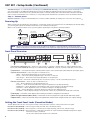
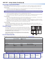
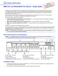
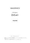
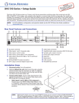
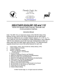
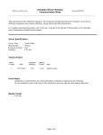
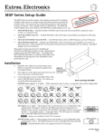
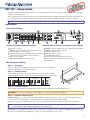
Product Category
USP 507 • Setup Guide
The Extron USP 507 (Universal Signal Processor) is a scaling product that allows most common signal formats to be processed and
output in any desired format.
This set up guide allows an experienced user to easily and quickly set up and configure a USP 507 using step by step instructions.
It covers performing basic operations using the front panel controls and selected Simple Instruction Set (SIS™) commands.
NOTE: For full installation, configuration, menus, and operation details, see the USP 507 User Guide at www.extron.com
Installation
Rear Panel Features
3
1
I
N
P
U
T
R/
R-Y
G/Y
VID
B/C 4
B-Y
V
R-Y
VID 5
/Y
VID
/Y
RGB/R-Y, Y, B-Y
2
RGB/R-Y, Y, B-Y
100-240 VAC 2A MAX
50-60Hz
1
2
4
3
B-Y
/C
HDSDI/
SDI
7
6
H/HV
DVI-D
C
5
15
10
7
G/
Y
R/
R-Y
O
U
T
P
U
T
B/
B-Y
RS-232
DVI
OUT
6
V
S
RGB/R-Y, B-Y, Y
9
8
Power and video input connections
RESET
LAN
H
13
12
AUX SW FOLL0W
MTP
14
11
Output, user interface, and control connections
a AC power connector
b RGB/HD, component, VGA connectors (inputs 1 and 2)
c Universal BNC connectors (input 3)
d Component/S-video/composite BNC connectors (input 4)
e S-video/composite video BNC connectors (input 5)
f DVI connector (input 6)
g (Optional) HD-SDI/SDI connector (input 7)
h RGB/HD, component, BNC connectors o Reset button and LED
i RGB/HD, component VGA connectors
j (Optional) output card*
k MTP twisted pair connector
l RJ-45 Ethernet connector
m Control device 9-pin D-sub RS-232 connector
n Auxilliary switcher 9-pin D-sub RS-232 connector
*DVI card shown
Mounting and Cabling
Step 1 — Mounting
Turn off or disconnect all equipment power sources and rack mount the USP 507
using the supplied brackets (see image at right).
Step 2 — Connect inputs
Connect inputs from video sources to the applicable connectors marked “Inputs”.
See b through g above for connector types and the image below for signal format.
RGsB/Component Video
(R-Y, Y, B-Y)
RGBS/ RGBcvS video
RGBHV
R/
R-Y
G/Y
VID
H/HV
V
B/C
B-Y
R/
R-Y
H/HV
G/Y
VID
V
B/C
B-Y
R/
R-Y
H/HV
G/Y
VID
V
B/C
B-Y
S-video
Composite
video
VID
/Y
VID
/Y
C
C
Rack Mount
Bracket
Step 3 — Connect outputs
Connect video output devices to the applicable connectors marked “Outputs” (see h through k above).
CAUTION Do not connect an MTP cable to the LAN port, or connect a LAN cable to the MTP port.
Step 4 — Connect control devices
LAN Ethernet port l — Connect an Ethernet LAN or WAN via this RJ-45 connector for remote control of the USP 507 using an
Internet browser on a connected PC, or the Extron Signal Processing Product Control Program (SPPCP).
One Ethernet connection LED lights green when connected to the LAN and one flickers amber as the devices communicate.
NOTE: Do not use standard telephone cables for LAN connection, as they do not support Ethernet or Fast Ethernet.
Do not stretch or bend cables as transmission errors could occur.
RS-232 ports — For serial RS-232 or RS-422 control, connect a host computer or control system to the upper 9-pin D connector m.
RS-232 protocol (default values): 9600 baud, 1 stop bit, no parity, 8 data bits, no flow control.
1
USP 507 • Setup Guide (Continued)
Aux SW Follow port — For auxiliary device switching; using a NULL RS-232 cable only, connect an Extron audio switcher/processor,
such as the SW 8A, to the lower 9-pin D-sub RS-232 connector n. When the USP 507 switches input via either a control device
RS-232 command, or front panel control, the USP 507 and the connected auxiliary device will switch inputs simultaneously. When
video is muted or unmuted, frozen or unfrozen, a corresponding audio mute/unmute command is sent to the auxiliary switcher.
Step 5 — Connect power
AC power connector — Plug in a standard IEC power cord from a 100 to 240 VAC, 50 - 60 Hz power source into this receptacle a.
Powering Up
When powering up the USP 507, the unit undergoes a self testing sequence (see image below). The LCD displays the default display
cycle, showing the output rate and the refresh rates for the currently selected input.
When not in any menu mode the screen cycles through the input/output configuration currently installed.
Apply
Power
Menu and Next
buttons remain lit.
1
sec.
10
sec.
Extron
USP 507
v1.xx
MENU
3
sec.
Input #2
60.0kHz
75.0Hz
2
2
sec.
Output Rate
1024x768 60.0Hz
2 sec.
Key
= unlit
2
1
1
1
Last active input sec.
button remains lit.
3
sec.
All buttons flash in sequence
(green, red, amber).
1
sec.
NOTE:
NEXT
Default Display Cycle
= lit
= flashing
When in use and not in any menu mode, the LCD screen defaults to cycling through the current input/output
status. The displayed content may vary depending on the input video signal type (see typical default display above).
Front Panel Overview
ADJUST
INPUTS
1
2
3
4
5
6
MUTE
AUTO
IMAGE
SIZE
BRIGHT
/CONT
DETAIL
MENU
FREEZE
PIP
PRESET
POSITION
COLOR
/TINT
ZOOM
/PAN
NEXT
7
USP 507
UNIVERSL SIGNAL PROCESSOR
1
2
3
4
5
6
7
a Front panel configuration port — Connect a control system or computer to this (RS-232) port, using a TRS RS-232 cable,
Extron part number 70-335-01. RS-232 protocol (default values): 9600 baud, 1 stop bit, no parity, 8 data bits, no flow control
b Input buttons — Selects/switches inputs, indicating which input is active (current input lights amber, PIP input lights green).
c Special function buttons — These four, dual colored buttons are:
• Mute — Allows the displayed image to be muted or umuted.
• Freeze — Allows the current displayed image to be frozen or unfrozen.
• Auto Image™— Allows automatic image adjustment on selected input.
• PIP Preset — Allows the current PIP layout to be saved as a preset, or recalls a saved PIP preset layout.
d Picture contol buttons — These six, dual colored buttons are:
• Size — Allows adjustment to the displayed image size.
• Position — Allows horizontal and/or vertical position adjustment of the displayed image.
• Bright/Cont — Allows adjustment of the brightness and contrast settings for the displayed image.
• Color/Tint — Allows adjustment of the color and tint settings for the displayed image.
• Detail — Allows adjustment of the detail (sharpness) setting for the displayed image.
• Zoom/Pan — Allows displayed image to be zoomed in or back out, or panned horizontally and/or vertically.
e LCD display — This 16x2 screen displays device settings and menu configuration information.
f Menu navigation buttons (Menu, Next) — These buttons allow navigation through the USP 507 menu system.
g Adjust knobs — These are used with the picture adjustment and the menu navigation buttons to adjust settings.
Setting the Front Panel Locks (Executive Modes)
The USP 507 has three modes of front panel security lock that limit the operation of the unit from the front panel.
Executive mode 0 (disabled) — The front panel is fully unlocked. This is the default setting.
Executive mode 1 (enabled) — The front panel is locked except for input switching, video freeze, and auto image.
Executive mode 2 (enabled) — The front panel is completely locked and can only be enabled and disabled using Extron Simple
Instruction Set (SIS™) commands.
See the online USP 507 User Guide for SIS commands.
2
Enabling or disabling Executive mode 1 from the front panel
LCD screen displays
either
If the USP 507 is in Executive mode 0 (unlocked), the procedure shown at right selects mode 1
(locked). If it is in Executive mode 1, this procedure selects mode 0 (unlocked).
When Executive mode 1 is enabled and a front panel action is attempted (other than video
freeze, input switching, PIP preset recall, and auto image), the status is displayed for 2 seconds.
Press and
hold for about
2 seconds.
Executive Mode
Enabled
SIZE
or
Executive Mode
Disabled
POSITION
Configuring the USP 507
The USP 507 can be configured by any of the following: via the front panel, the Extron Signal Processing Products Control Program,
through the internal web page, or via RS-232/Ethernet using SIS commands (see rear page).
Front Panel
The processor has seven front panel configuration menus: User Presets, Input Configuration, Output Configuration, Image Capture/
Recall, Advanced Configuration, View Comm Settings, and Exit Menu. A hidden menu (Edit Comm Settings) is also accessible. A
Scan Converter or Aux Scaler menu appears if an optional card is installed.
User
Presets
Menu
Input
Configuration
Menu
Output
Configuration
Menu
Image
Capture/Recall
Menu
Advanced
Configuration
Menu
View Comm
Settings
Menu
Scan
Converter
Menu
Exit Menu
Press NEXT
or
Aux
Scaler
only where an optional
card is installed
To use any menu, press the Menu button to access the main menu, then repeatedly press the Menu button to cycle through to the
desired menu. Press the Next button to enter and cycle through the desired submenu.
NOTE:
Press Menu at any time to exit a submenu and return to the main menu.
For detailed information on the menus, see the USP 507 User Guide, available online at www.extron.com.
To configure the USP 507 using the front panel, follow the steps below:
1.
Within the Output Configuration menu, use the Adjust knobs to configure the output rate and resolution, the output
signal type, and the sync polarity to match the requirements of the display device.
2.
From the Advanced Configuration menu, Test Pattern submenu, select the Alternating Pixels (Alt. Pixels) test pattern.
Adjust the active pixels (size), total pixels (clocking), and pixel phase (fine sync) settings for optimal picture quality.
3.
From the Advanced Configuration menu, change the test pattern to Crop, and adjust the display's position settings until
all four sides of the crop pattern are visible. Disable the test pattern. No further adjustments or Auto Images should be
performed on the display device.
4.
Use the Advanced Configuration menu to set the Aspect ratio (Fill or Follow). Rotate either Adjust knob to the desired
setting.
5.
Perform Auto-Image on each USP 507 input. Auto-Image is a quick way to size an input to fit the current window size. To
perform Auto-Image on an input, press the Auto Image button then press it again to confirm.
Alternatively; use the Input Configuration menu to make any desired advanced adjustments, including turning on or off
Film detection, Horizontal and Vertical Start, Pixel Phase, Total Pixels, Active Pixels, and Active Lines.
6.
Use the Picture Control buttons to adjust Size, Position, Brightness, Contrast, Color, Tint, Detail, Zoom, and Pan if needed.
7.
Use the User Presets menu to save the adjustments to each input for manual recall later.
Signal Processing Product Control Program
To configure the unit using SPPCP, the program must be installed (from the included DVD or download from www.extron.com) on
a PC that is connected to the USP 507 via an RS-232 or a LAN connection. The installation creates a C:\Program Files\Extron\
Signal Processing folder and installs the SPPCP program, a Help file, and an Uninstall SPPCP program.
Once installed, start the SPPCP program and either connect via the comm (RS-232) port or by TCP/IP. For full SPPCP instructions press
<F1> or click on Help, Contents.
Web page
The USP 507 can be configured, controlled, and operated through its Ethernet port, connected to a LAN or WAN, using a Web
browser such as Microsoft® Internet Explorer®. The browser displays the unit factory-installed Web pages, which provide a means
of viewing and operating the device. Access the HTML pages by entering the IP address of the unit in the browser Address field.
NOTE: If the system administrator has not changed it, the factory-specified default IP address is 192.168.254.254.
If the unit is password protected, enter the administrator or user password in the Password field. A user name entry is
not required.
3
USP 507 • Setup Guide (Continued)
Using Image Capture/Recall Menu
The Image Capture/Recall menu allows any one of up to 16 stored images to be recalled to the display, as either a background to
an active video signal, or in front of the active signal. It also allows the user to store the current displayed image for later recall.
To save an image:
From within the Image Capture/Recall menu, press Next (the LCD displays “Save As: <N/A>”) and use either Adjust knob to
scroll through 16 image names (IMG01.bmp through IMG16.bmp).
1.
NOTE: When saving an image to a selected name, any image previously saved with that name is overwritten by the new image.
2.
Press Next. The LCD displays “[Detail] = Confirm”, and the Detail button flashes red.
3.
Press the detail button. The LCD changes to “Saving image Please wait”, then to “Saving image”. A progress bar indicates
the progress of the image capture process. When the image is saved the LCD reverts to the default menu.
To recall an image:
1.
From within the Image Capture/Recall menu, press Next until the LCD displays “Recall to back: <N/A>”, or “Recall to front:
<N/A>”. Select as desired and use either Adjust knob to scroll to the desired image.
2.
Press Next to recall the image. While rendering, the LCD displays “Recalling image Please wait”. When the image is
fully rendered, the name of the image is shown and “Recalled”, (for example, “IMG05.bmp Recalled”). The recalled
image is now on the active display. Press Next to exit the Recall Image menu.
To remove an image:
Press Next while the LCD displays “Recall to back: <N/A>”, and again when it states “Recall to front: <N/A>”, until
“Image Capture/Recall" is displayed. Press Menu to exit the Image Capture/Recall menu. The image is removed from the
display screen but remains in the memory of the USP 507.
Using PIP Presets
The PIP Preset button allows any one of up to 16 PIP window layouts to be recalled
to the display, or allows the user to save a PIP layout for later recall. Of the 16 layouts,
ten are factory default positions (shown at right). The other six are user customizable.
33
44
7
8
22
11
6
5
To recall a layout: Press the PIP Preset buttons and scroll to the desired layout using
the adjust knob. Press Next to recall the layout.
9
To save a layout as a preset: Press and hold the PIP Preset button until the LCD
displays “Save to PIP Preset”. Use either adjust knob to scroll to the desired layout.
Press Next to save the layout.
Main =
10
PIP =
Basic SIS Commands Table
The USP 507 can be configured with specific SIS commands via RS-232 or a LAN connection. This table lists a selection of the
commands. For a full list of SIS commands refer to the USP 507 User Guide, online at www.extron.com.
Command
ASCII command
(host to switcher)
Additional description
Select input
X!!
InX!]
Select video from input X!.
Execute Auto-Image
A
Img]
Execute auto image for current input.
Mute video to black
1B
Vmt1]
Mute video and display a black screen.
Unmute video
0B
Vmt0]
Unmute the video.
Freeze input
1F
Frz1]
Freeze selected input.
Unfreeze input
0F
Frz0]
Unfreeze selected input.
PIP on
EX!Pip}
PipX!]
Turn on PIP and display input X!.
PIP off
E0pip}
Pip0]
Turn off PIP.
Swap
%
Tke]
Swap between main and PIP windows.
Recall PIP preset
3*X2^.
3RprX2^]
Recalls PIP preset.
Save PIP preset
3*X2^,
3SprX2^]
Saves PIP preset.
NOTE: X! = Input number (1 – 7)
X2^ = PIP presets (1-16)
Extron USA - West
Headquarters
Extron USA - East
Extron Europe
Extron Asia
Extron Japan
Extron China
Extron Middle East
+800.633.9876
+800.633.9876
+800.3987.6673
+800.7339.8766
Inside Asia Only
+81.3.3511.7655
+81.3.3511.7656 FAX
+400.883.1568
Inside Europe Only
+971.4.2991800
+971.4.2991880 FAX
+1.919.863.1794
+1.919.863.1797 FAX
+31.33.453.4040
+31.33.453.4050 FAX
+65.6383.4400
+65.6383.4664 FAX
Inside USA/Canada Only
4
Response
(switcher to host)
+1.714.491.1500
+1.714.491.1517 FAX
Inside USA/Canada Only
Inside China Only
+86.21.3760.1568
+86.21.3760.1566 FAX
© 2011 Extron Electronics All rights reserved. www.extron.com
68-1796-50
Rev. B
05 11