1
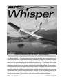
Instructions for Final Assembly
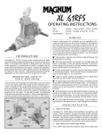
The Wattage Whisper is a 2-meter electric powered glider utilizing all balsa and plywood built up
construction techniques. The polyhedral wing design is a flat bottom, Phillips Entry style that is incredibly
stable throughout the entire flight envelope and produces good lift. The wing is built of true D-Tube
construction with balsa sheeting and shear webbing for great strength. The fuselage is built up light
plywood and balsa and the tail feathers are built up of lightweight balsa. Lightening holes have been
strategically placed to remove unnecessary weight without compromising strength. All this adds up to
an airplane that climbs out with authority and will also do well in the thermals. Included is a 540 direct
drive electric motor with folding propeller assembly and all wiring preinstalled at the factory. All necessary
hardware is included to finish the kit, including clevises, pushrods, control horns and all of the necessary
nuts and bolts, even a molded cowling and canopy! We hope you will enjoy building and flying the
Whisper as much as we have enjoyed designing it for you. Please fill out the Product Evaluation Sheet
at the end of this manual. We would love to hear your comments regarding the Whisper.
Version
V1.0
9-99 MTN
All Contents © Copyright 1999
1
TABLE OF CONTENTS
Our Recommendations....................................................2
Pushrod Installation.......................................................15
Metric Conversion Chart.................................................2
Kit Contents.....................................................................3
Installing the Pushrod Housings.............................15
Installing the Elevator Control Horn......................16
Additional Items Required..............................................4
Installing the Rudder Control Horn........................16
Tools and Supplies Needed.............................................4
Installing the Elevator Pushrod..............................17
Full Size Hardware Drawings.........................................5
Installing the Rudder Pushrod................................18
Motor Break-in...............................................................6
Motor Installation..........................................................18
Wing Assembly...............................................................7
Laminating the Dihedral Braces..............................7
Installing the Motor................................................18
Cowl and Propeller Installation.....................................19
Installing the Outboard Dihedral Braces.................7
Joining the Cowl Halves........................................19
Installing the Propeller...........................................20
Joining the Outboard Wing Panels..........................8
Installing the Cowl.................................................20
Joining the Wing Halves.........................................8
Canopy Installation.......................................................21
Installing the Striping Tape.....................................9
Aligning the Canopy..............................................21
Mounting the Canopy.............................................21
Installing the Wing Hold Down Strip....................10
Wing Installation...........................................................10
Landing Skid Installation..............................................22
Installing the Front Wing Dowels..........................10
Installing the Landing Skid....................................22
Installing the Rear Wing Dowel.............................11
Final Assembly..............................................................22
Installing the Wing.................................................11
Installing the Receiver...........................................22
Horizontal Stabilizer Installation...................................11
Aligning the Horizontal Stabilizer..........................11
Installing the Switch...............................................22
Installing the Receiver and ESC............................22
Mounting the Horizontal Stabilizer........................12
Balancing.......................................................................23
Hinging the Elevator..............................................12
Control Throws.............................................................23
Vertical Stabilizer Installation.......................................13
Flight Preparation.........................................................23
Hinging the Rudder................................................13
Aligning the Vertical Stabilizer..............................13
Preflight Check......................................................24
ABC's of Flying............................................................24
Mounting the Vertical Stabilizer.............................14
Basics of Flight..............................................................25
Installing the Tail Fairing.......................................14
Basics of Thermal Flying..............................................27
Servo Installation...........................................................15
Glossary of Terms.........................................................28
Installing the Servo Tray........................................15
Notes..............................................................................29
Installing the Servos...............................................15
Product Evaluation Sheet..............................................30
Wattage guarantees this kit to be free from defects in both material and workmanship, at the date of purchase. This
does not cover any components parts damaged by use, misuse or modification. In no case shall Wattage's liability
exceed the original cost of the purchased kit.
In that Wattage has no control over the final assembly or material used for final assembly, no liability shall be assumed
for any damage resulting from the use by the user of the final user-assembled product. By the act of using the final
user-assembled product, the user accepts all resulting liability.
To make your modeling experience totally enjoyable, we recommend that you get experienced, knowledgable help
with assembly and during your first flights. Your local hobby shop has information about flying clubs in your area
whose membership includes qualified instructors. You can also contact the AMA at the address below.
Academy of Model Aeronautics
5151 East Memorial Drive
Muncie, IN. 47302-9252
(800) 435-9262
www.modelaircraft.org
2
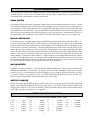
OUR RECOMMENDATIONS
The following items are our recommendations to help you in deciding which types of accessories to purchase for
your new Whisper. We have tested all of these items, and many others with the Whisper, and found that these
will offer the best in performance, reliability and economy.
RADIO SYSTEM
The Wattage Whisper will require a minimum 3 channel radio control system that includes two servos. For this
we recommend the Hitec Focus 3 channel radio with two standard servos. If you already own a radio system, or
want to purchase a radio system that will be more upgradeable in the future, a four or more channel radio with
two standard servos will work fine. Our recommendation would be the Hitec Flash 4X FM Computer radio.
This is a very good system that offers the ability to grow as your experience grows. A standard size receiver will
fit in the Whisper with no problems, so the purchase of an aftermarket micro or mini receiver is unnecessary.
MOTOR CONTROLLER
To operate the motor, we highly suggest using a proportional electronic speed control that features B.E.C. circuitry, auto-cutoff and a brake. B.E.C. circuitry allows you to eliminate the receiver battery and uses the motor
battery to control both the motor and the servos. Eliminating the receiver battery provides a great weight savings
which effectively increases performance. The auto-cutoff feature turns off the motor when the voltage in the
battery drops too low to operate the radio system safely. This guarantees safe operation throughout the entire
flight. The brake feature electronically causes the motor to stop rotating allowing the folding propeller to fold
properly. This will prevent excessive strain and current draw in the electronic components, specifically the
motor controller. To obtain all of these features, we suggest using one of the Wattage Electronic Speed Controls
available for 540 and 05 size motors. If you opt not to use a proportional electronic speed control, an electronic
switch such as the Hitec Motor Controller SP-1003 (part # 41003) is an economical way to turn the motor on and
off. This switch does not offer any proportional speed, only off or full power.
MOTOR BATTERY
The battery you choose should be a 7 cell (8.4v) Nickel Cadmium battery pack. Choose a battery pack between
1100Mah and 2000Mah. A premade R/C car battery such as the Trinity 1400Mah flat pack (part # 842010)
works very good. A 6 cell battery pack will fly the Whisper, however climb out will be slower than if you use a
7 cell pack. Today's new generation of Sub-C 3000Mah Nickel Metal Hydride batteries also perform well,
however require a linear charger featuring adjustable peak cutoff voltage.
BATTERY CHARGER
Because the battery powers both the motor and the radio system, we suggest using an automatic Delta Peak
charger such as the Promax Black Widow Peak Charger (part # 35036) or the Promax Activator Digital Peak
Charger (part # 885650). It is vital to the Whisper's flying performance that the battery pack be fully charged
every flight, so using a peak charger is very important.
METRIC CONVERSION CHART
To convert inches into millimeters: Inches x 25.4 = MM
1/64”
1/32”
1/16”
3/32”
1/8”
5/32”
=
=
=
=
=
=
.4mm
.8mm
1.6mm
2.4mm
3.2mm
4.0mm
3/16”
1/4”
3/8”
1/2”
5/8”
3/4”
=
=
=
=
=
=
4.8mm
6.4mm
9.5mm
12.7mm
15.9mm
19.0mm
1”
2”
3”
6”
12”
18”
3
=
=
=
=
=
=
25.4mm
50.8mm
76.2mm
152.4mm
304.8mm
457.2mm
21”
24”
30”
36”
=
=
=
=
533.4mm
609.6mm
762.0mm
914.4mm
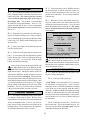
This instruction manual is designed to help you build a straight, great flying airplane. Please read this manual
thoroughly before beginning assembly of your new Wattage Whisper ARF. Use the parts photos below to
identify and separate all of the parts before beginning assembly.
**KIT CONTENTS** We have organized the parts as they come out of the box for better identification
during assembly. Each photo below represents parts that are required for each step in the assembly process.
We recommend that you regroup the parts in the same manner. This will ensure you have all of the parts
required before you begin assembly and will also help you familiarize yourself with each part. The corresponding part number is listed first, then the quantity of the part is listed, along with it's description.
KIT CONTENTS
PROPELLER ASSEMBLY
WOOD PARTS
2
7
23
21
6
3
24
3
22
1
20
4
8
18
5
1
2
3
4
5
6
7
8
q
q
q
q
q
q
q
q
{1}
{1}
{2}
{1}
{1}
{1}
{1}
{3}
19
Nylon Propeller Hub
Nylon Spinner Cone
Propeller Blade Halves
Tapered Aluminum Hex Adapter
Threaded Adapter
Propeller Washer
Propeller Nut
2mm x 12mm Smooth Shank Machine Screws
18
19
20
21
22
23
24
q
q
q
q
q
q
q
{1}
{2}
{2}
{4}
{2}
{1}
{1}
6mm x 95mm Rear Wing Hold Down Dowel
6mm x 32mm Front Wing Hold Down Dowels
Front Wing Hold Down Dowel Blocks
Outboard Wing Panel Dihedral Braces
Inboard Wing Panel Dihedral Braces
Servo Tray
Servo Tray Support
MOTOR ASSEMBLY
PUSHROD ASSEMBLIES
11
26
14
25
9
12
13
10
28
15
31
16
27
17
25
9
10
11
12
13
14
15
16
17
q
q
q
q
q
q
q
q
q
{2}
{2}
{1}
{1}
{2}
{2}
{4}
{2}
{1}
2mm x 610mm Threaded Pushrods
3mm x 640mm Nylon Pushrod Housings
3mm x 55mm x 14mm Pushrod Support
8mm x 20mm Clear Tubing
Metal Clevises
Nylon Control Horns w/ Backplates
2mm x 15mm Machine Screws
Adjustable Servo Connector Assemblies
Hex Wrench
26
27
28
29
30
31
4
q
q
q
q
q
q
q
{1}
{2}
{2}
{4}
{4}
{4}
{8}
Electric Motor
Motor Mount Halves
3mm x 8mm Machine Screws
3mm x 12mm Machine Screws
3mm Flat Washers
3mm Nylon Insert Nuts
2mm x 12mm Wood Screws
29
30
MOLDED PLASTIC PARTS
MAIN AIRFRAME ASSEMBLIES
33
38
41
32
34
39
40
36
40
39
37
35
32
33
34
35
36
37
q
q
q
q
q
q
42
{1} Molded Plastic Canopy
{2} Molded Plastic Cowl Halves, Right & Left
{1} Trim Tape (1 White, 2 Blue, 1 Red & White)
{1} 15mm x 100mm Plastic Strip
{1} Molded Plastic Tail Fairing
{1} Molded Landing Skid
38
39
40
41
42
q
q
q
q
q
{1}
{2}
{2}
{1}
{1}
Fuselage
Inboard Wing Panels
Outboard Wing Panels
Horizontal Stabilizer w/Elevator &Hinges
Vertical Stabilizer w/Rudder & Hinges
ADDITIONAL ITEMS REQUIRED
Recommended
1
2
3
4
4
1
5
q Hitec Focus 3 AM Single Stick Radio w/2 Servos
Requires 8 AA Batteries # AC8AA
q Wattage ESC with BEC and Brake
q Trinity 7 Cell 1400 Mah Amp Max Battery # 842010
q Promax Black Widow Peak Charger # 350360
q Arco # 64 Rubber Bands # 24649
Optional Upgrades
2
q Hitec Flash 4X FM Computer radio w/2 Servos
q Trinity 7 Cell 1700Mah Battery # 1779
q Promax Activator Digital Peak Charger # 885650
3
5
TOOLS AND SUPPLIES NEEDED
1
2
4
3
4
1
5
2
6
7
16
8
14
9
3
10
7
5
13
11
17
12
11
13
12
6
9
10
15
14
15
8
16
17
(Some Items Listed are Not Shown)
5
q
q
q
q
q
q
q
q
q
q
q
q
q
q
q
q
q
q
q
Kwik Bond 5 Minute Epoxy # 887560
Kwik Bond Thick C/A # 887510
Trinity Bushing Oil # 4049
Performance Plus Motor Spray # 4000
Excell Modeling Knife # 16018
Pliers
8mm Wrench or Adjustable Wrench
Straight Edge Ruler
Builders Triangle
# 0 and # 2 Phillips Screwdrivers
Hand or Electric Drill
1/16”, 5/64”, 1/8” and 1/4” Drill Bits
TS Racing Zip Ties # TS-006B
220 Grit Sandpaper w/Sanding Block
Paper Towels
Rubbing Alcohol
Clamps
Pen
Masking Tape
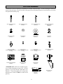
FULL SIZE DRAWINGS
Listed below are full size drawings of the hardware included with the Whisper. Use these drawings to familiarize
yourself with each piece. Please refer back to this page to locate the proper hardware items when they are needed
for a particular assembly step.
3mm x 12mm Machine Screw
(Quantity 4)
3mm x 8mm Machine Screw
(Quantity 2)
2mm x 15mm Machine Screw
(Quantity 4)
2mm x 12mm Smooth Shank
Machine Screw
(Quantity 3)
3mm Nylon Insert Nut
(Quantity 4)
3mm Flat Washer
(Quantity 4)
Propeller Washer
(Quantity 1)
Propeller Nut
(Quantity 1)
Servo Connector Body
(Quantity 2-Part of Servo Connector
Assembly)
2mm Set Screw
(Quantity 2-Part of Servo Connector
Assembly)
2mm Hex Nut
(Quantity 2-Part of Servo Connector
Assembly)
2mm x 12mm Wood Screw
(Quantity 8)
Aluminum Prop Shaft Adapter
(Quantity 1)
Tapered Hex Adapter
(Quantity 1)
Nylon Backplate
(Quantity 2)
**IMPORTANT** We have included a glossary of terms beginning on page # 28. Use this
glossary if you come across a term that is unfamiliar. Terms throughout this instruction
book that are written in bold are listed in the
glossary.
Nylon Control Horn
(Quantity 2)
Metal Clevis
(Quantity 2)
6
If you should find a part missing or have questions about assembly, please call or write to the address below:
Wattage Customer Care
18480 Bandilier Circle
Fountain Valley, CA. 92728
Phone: (714) 963-0329
Fax: (714) 964-6236
E-Mail: [email protected]
**SUGGESTION** To avoid scratching your new airplane, do not unwrap the pieces until they are
needed for assembly. Cover your workbench with an old towel or brown paper, both to protect the aircraft
and to protect the table. Keep a couple of jars or bowls handy to hold the small parts after you open the
plastic bags.
**NOTE** Please trial fit all of the parts. Make sure you have the correct parts and that they fit and are
aligned properly before gluing! This will assure proper assembly. Since the Whisper is hand made from
natural materials, every airplane is unique and minor adjustments may have to be made. However, you
should find the fit superior and assembly simple.
q 6) With the motor turned off, test the operation
of the servos. They should move when you move the
control stick.
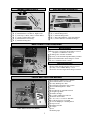
MOTOR BREAK-IN
q 1) Set out the electric motor, battery, charger,
radio system and the electronic speed control onto
your workbench.
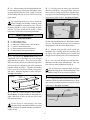
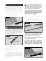
q 7) Carefully spray a couple of light sprays of
motor spray inside the motor opening and apply a
small drop of bushing oil onto each of the two motor
bushings. See photo # 1 below.
q 2) Charge the motor battery using the peak
charger according to the charger's instructions. Install the 8 AA batteries into the transmitter (Focus 3)
or fully charge the transmitter batteries (radios using
rechargeable batteries).
Photo # 1
q 3) Once the batteries are ready, plug the two
servos and electronic speed control into the receiver.
Plug the motor lead into the speed control lead.
Motor
Opening
The prewired plastic connector on the motor is
called a Tamiya Connector. Most electronic
speed controls also use this style of connector, but
some do not. If your speed control does not have this
type of connector, you will need to change the connector to a compatible one at this time.
q 8) Using paper towels, wipe off the excess oil.
q 9) Slowly turn on the motor using the transmitter throttle lever. Position the throttle lever to about
1/3 throttle and let the motor run. While the motor is
running, apply a light spray of motor spray inside the
motor opening once every minute, followed by a drop
of oil on each bushing. Do this until the battery is
fully discharged (i.e. the motor stops).
q 4) Set the motor, without the propeller installed,
between the handles of a pair of pliers. Secure the
motor to the handles using three # 64 rubber bands.
This will keep the motor secure enough for the breakin procedure.
q 5) Turn on the transmitter and then plug the
motor battery into the speed control. If the motor
immediately turns on, use the throttle stick (on the
Focus 3, the throttle lever is on the back of the transmitter) to turn off the motor.
If you have chosen a on-off only motor controller, complete the same process but only run
the motor in two minute intervals, letting the motor
cool between each interval.
7
q 10) After the battery has discharged and the motor has stopped, spray motor spray through the motor
opening until the fluid runs clear. Apply oil to both
of the bushings and wipe away all of the excess using
paper towels.
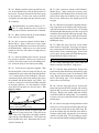
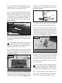
q 3) Carefully place the brace, glue side down,
onto the second brace. Line up the edges of the two
braces and use clamps to hold them together tight.
Use a paper towel and rubbing alcohol to remove any
excess epoxy before it cures. See photo # 2 below.
Photo # 2
By completing these steps, you’ve seated the
motor bushings and brushes, tested the radio
system, and cycled the motor battery once. The motor battery should be cycled 3 times before the plane
is flown. Typically, nicads must be cycled 3-5 times
before they work to their maximum performance.
Clamp
WING ASSEMBLY
Clamp
q 4) Repeat steps # 2 - # 3 to laminate together
the four outboard dihedral braces. Remember to make
two sets. You should now have two sets of outboard
dihedral braces and one center dihedral brace.
PARTS REQUIRED
q
q
q
q
q
q
{2}
{2}
{1}
{1}
{4}
{2}
Inboard Wing Panels
Outboard Wing Panels
Trim Tape (1 White, 2 Blue, 1 Red & White)
15mm x 100mm Plastic Strip
Outboard Wing Panel Dihedral Braces
Inboard Wing Panel Dihedral Braces
q 5) After the epoxy has fully cured, use 220 grit
sandpaper with a sanding block and carefully sand
the edges of the three dihedral braces smooth and
straight. Be careful not to take off too much material.
LAMINATING THE DIHEDRAL BRACES
q 1) Lay out the six dihedral braces onto your
workbench. Four of the braces are cut at a deeper
angle than the two others. These four are the dihedral braces used to join the two outboard wing panels
to the two inboard wing panels and will be laminated
together to make two braces. The other two dihedral
braces are used to join the two inboard wing panels
and will be laminated together to make one brace.
See figure # 1 below.
Figure # 1
Dihedral
Brace
q 6) Use a pen and label the two outboard dihedral braces and the center dihedral brace. This will
help you keep from getting them mixed up.
The two braces cut at a deeper angle are for the
outboard wing panels. The remaining brace with
the shallower angle is for the center wing panels.
INSTALLING THE OUTBOARD DIHEDRAL BRACES
Dihedral
Brace
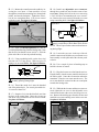
q 7) Using a ruler and a pen, locate and mark the
centerlines of the two outboard dihedral braces. Draw
one vertical line at this location on each side of both
of the braces. See photo # 3 below.
Photo # 3
Dihedral
Brace
Draw
Centerline
q 2) Mix up a small amount of Kwik Bond 5
Minute Epoxy. Working with the two inboard braces,
apply a thin layer of epoxy to only one side of only
one of the two braces.
Dihedral Brace
For the epoxy to work properly, mix equal
amounts of part A and part B. Mix the two parts
together for about 45 seconds until they are both thoroughly mixed.
8
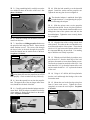
q 8) Working with one outer wing panel and one
outer dihedral brace for now, test fit the dihedral
brace into the plywood box in the outer wing panel.
The brace should slide into the wing panel up to the
centerline. If it does not, remove the brace and
lightly sand the edges and tips of the brace until the
proper fit is obtained. See photo # 4 below.
Figure # 2
Inboard Wing
Panel
Outboard
Wing Panel
2-3/4”
Flat Work Surface
Photo # 4
The wing panels should fit together tight with
little or no gaps in the joint. If the joint is not
tight, remove the wing panels and lightly sand the
edges and tips of the dihedral brace. Test fit the wing
panels together once more. Repeat this until you are
satisfied with the fit of the wing panels.
Dihedral
Brace
Outboard
Wing Panel
q 14) Mix a generous amount of Kwik Bond 5
Minute Epoxy. Apply a thin layer of epoxy to the
exposed half of the dihedral brace, the inside of the
plywood box in the inboard wing panel and the entire
surface of both ribs. Make sure to use enough epoxy
to fill any gaps.
The dihedral brace is cut in the shape of a "V".
The "V" shape should face the top surface of
the wing (curved surface) when the brace is installed.
q 9) When satisfied with the fit of the dihedral
brace, remove it from the wing panel.
q 15) Slide the two wing panels together and carefully align them at the leading and trailing edges.
Align the wing panels as done in step # 13, keeping
the inboard panel flat and using a book or scrap wood
to hold the outboard panel at the proper height. Wipe
away any excess epoxy using a paper towel and rubbing alcohol and allow the epoxy to fully cure before
handling the wing.
q 10) Mix a generous amount of Kwik Bond 5
Minute Epoxy. Apply a thin layer of epoxy inside
the plywood dihedral brace box and to only half of
the dihedral brace. Make sure to cover the top and
bottom as well as the sides, and use enough epoxy to
fill any gaps.
q 11) Slide the dihedral brace into the plywood
box up to the centerline. Remove any excess epoxy
before it dries using a paper towel and rubbing alcohol. Allow the epoxy to cure before proceeding.
After the epoxy has completely cured, use a ruler
and check the final dihedral angle of the outboard panel. If it is not exactly 2-3/4”, that is okay.
When you join the opposite two panels together, make
sure that angle is the same angle as the first. To help
visualize this you can place the two sets of wing panels next to each other to double check your work.
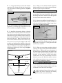
q 12) Repeat steps # 8 - # 11 to install the second
outboard dihedral brace into the second outboard
wing panel.
JOINING THE OUTBOARD WING PANELS
q 13) Working with the right outboard wing panel
and the right inboard wing panel for now, test fit the
two wing panels together. With the inboard panel
flat on your workbench, the tip of the outer wing panel
should be 2-3/4” off the surface of the workbench.
This measurement should be taken at the trailing edge
of the outer panel where the tip begins. Use books or
a scrap piece of wood to hold the wing panel in the
proper position. It is also helpful to weight down the
inboard panel so it does not move. Magazines work
good for this. See figure # 2 at top right.
q 16) Repeat steps # 13 - # 15 to join the left outboard wing panel and the left inboard wing panel.
Once that is complete you should have one right and
one left wing half.
JOINING THE WING HALVES
q 17) Using a ruler and a pen, locate and mark the
centerline of the center dihedral brace. Draw one vertical line at this location on each side of the brace.
9
q 18) Working with the right wing half for now,
test fit the dihedral brace into the plywood box in
the root rib. The brace should slide into the wing up
to the centerline. If it does not, remove the brace
and lightly sand the edges and tips until the proper
fit is obtained.
q 23) Mix a generous amount of Kwik Bond 5
Minute Epoxy. Apply a thin layer of epoxy to the
exposed half of the dihedral brace, the inside of the
plywood box in the root rib and the entire surface of
both root ribs. Make sure to use enough epoxy to fill
any gaps.
The dihedral brace is cut in the shape of a "V".
The "V" shape should face the top surface of
the wing (curved surface) when the brace is installed.
q 24) Slide the two wing halves together and carefully align them at the leading and trailing edges.
Align the wing halves as done in step # 22, keeping
the inboard panel flat and using a book or scrap wood
to hold the right wing half at the proper height. Wipe
away any excess epoxy using a paper towel and rubbing alcohol and allow the epoxy to fully cure before
handling the wing.
q 19) When satisfied with the fit of the dihedral
brace, remove it from the wing half.
q 20) Mix a generous amount of Kwik Bond 5
Minute Epoxy. Apply a thin layer of epoxy inside
the plywood dihedral brace box and to only half of
the dihedral brace. Make sure to cover the top and
bottom as well as the sides, and use enough epoxy to
fill any gaps.
q 21) Slide the dihedral brace into the plywood
box up to the centerline. Remove any excess epoxy
before it dries using a paper towel and rubbing alcohol. Allow the epoxy to cure before proceeding.
q 22) Test fit the two wing halves together. With
the inboard panel of the left wing half flat on your
workbench, the joint in the right wing half should be
1-3/4” off the surface of the workbench. This measurement should be taken at the trailing edge where
the outboard and inboard panels were joined. Use
books or a scrap piece of wood to hold the wing half
in the proper position. It is also helpful to weight
down the left wing half so it does not move. See
figure # 3 below.
Figure # 3
Right Wing
Half
Left Wing
Half
q 25) When the epoxy has fully cured, double
check all three wing joints. If any gaps are present,
mix a small amount of Kwik Bond 5 Minute Epoxy
and carefully fill any remaining gaps. Remove the
excess epoxy using a paper towel and rubbing alcohol and allow the epoxy to fully cure.
INSTALLING THE STRIPING TAPE
q 26) Using a modeling knife, cut the white self
adhesive trim tape into three 9” long pieces.
q 27) Turn the wing upside down. Remove the
paper backing from the trim tape and carefully apply
the tape over the three joints on the bottom of the
wing. Begin at the leading edge and carefully work
back to the trailing edge. Use a modeling knife to
remove the excess trim tape.
q 28) Turn the wing right side up. Remove the
paper backing from the blue trim tape and carefully
apply the tape over the two outboard joints on top of
the wing. Begin at the leading edge and carefully
work back toward the trailing edge. Use a modeling
to remove the excess material from the leading and
trailing edges.
1-3/4”
Flat Work Surface
(Portion of Left Wing Half Not shown for Clarity)
The wing halves should fit together tight with
little or no gaps in the joint. If the joint is not
tight, remove the wing halves and lightly sand the
edges and tips of the dihedral brace. Test fit the wing
halves together once more. Repeat this until you are
satisfied with the fit.
q 29) Remove the paper backing from the red and
white piece of trim tape and carefully apply the tape
over the center section joint on top of the wing. Begin at the leading edge and carefully work back toward the trailing edge, aligning the red on the tape
with the red on the wing. Use a modeling to remove
the excess material from the leading and trailing edges.
10
INSTALLING THE WING HOLD DOWN STRIP
q 30) Using a ruler and a pen, measure and mark
the center of the 15mm x 100mm white plastic strip.
q 31) Position the strip on top of the wing. The
back edge of the strip should be flush with the trailing edge of the wing and the centerline of the strip
should be lined up with the centerline of the wing.
See photo # 5 below.
q 2) Test fit one of the 6mm x 32mm front wing
hold down dowels into the predrilled hole in one
front wing hold down dowel mounting block. One
end of the dowel should be flush with the side of the
block. See photo # 6 below.
Photo # 6
Front Wing
Hold Down
Dowel
Dowel
Should Be
Flush
Photo # 5
Plastic
Strip
Hold Down
Dowel
Mounting
Block
Wing
Center
Section
q 32) While holding the strip in place, use a pen
and carefully draw around the strip to outline it onto
the wing surface.
q 33) Remove the plastic strip. Using a modeling
knife, carefully remove the covering from just inside
the outline. Use 220 grit sandpaper and lightly sand
the bottom of the plastic strip to roughen the surface.
q 34) Mix up a small amount of Kwik Bond 5
Minute Epoxy. Apply a thin layer to the bottom side
of the strip and realign it on the wing. Remove any
excess epoxy using a paper towel and rubbing alcohol. Hold the strip in place using pieces of masking
tape until the epoxy has fully cured.
q 3) When satisfied with the fit, remove the dowel
and mix a small amount of Kwik Bond 5 Minute Epoxy. Apply a thin layer of epoxy into the predrilled
hole in the block. Reinstall the dowel, keeping one
end of the dowel flush with the side of the block. Remove any excess epoxy using a paper towel and rubbing alcohol and allow the epoxy to fully cure.
q 4) Insert the dowel and block assembly through
the predrilled hole from inside the fuselage. The
dowel slides through the predrilled hole in the side
of the fuselage and the block should be pushed firmly
against the fuselage side and the forward bulkhead.
See photo # 7 below.
Photo # 7
Wing Dowel
Wing Dowel
Block
WING INSTALLATION
PARTS REQUIRED
Forward
Bulkhead
q {1} 6mm x 95mm Rear Wing Hold Down Dowel
q {2} 6mm x 32mm Front Wing Hold Down Dowels
q {2} Front Wing Hold Down Dowel Mounting Blocks
INSTALLING THE FRONT WING DOWELS
q 1) Using a modeling knife, remove the covering from over the two predrilled wing hold down
dowel holes in front of the wing saddle. One hole is
located on each side of the fuselage 4-7/8” behind the
front of the fuselage and 1/2” down from the top of
the fuselage.
11
If you look carefully at the block, you will notice that the top of the block is cut at an angle.
This angle matches the angle of the top of the fuselage. Depending on which side of the block you installed the dowel into, will determine which side of
the fuselage the block is glued to. When you make
the second dowel and block assembly later, make sure
you install the dowel on the opposite side as the first.
This way you will have made one right and one left
assembly.
q 5) Remove the assembly and mix a small amount
of Kwik Bond 5 Minute Epoxy. Apply a thin layer of
glue to the inside of the predrilled hole in the fuselage side and to the gluing surfaces of the block.
Reinstall the block and remove any excess epoxy using a paper towel and rubbing alcohol. Allow the
epoxy to fully cure before proceeding.
q 6) Repeat steps # 2 - # 5 to assemble and install
the second front wing hold down dowel assembly.
INSTALLING THE REAR WING DOWEL
q 7) Using a modeling knife, remove the covering from over the two predrilled wing hold down
dowel holes in back of the wing saddle. One hole is
located on each side of the fuselage 13-3/4” behind
the front of the fuselage and 3/8” down from the top
of the fuselage.
q 8) Slide the 6mm x 95mm rear wing hold down
dowel through the predrilled holes and center the dowel.
The ends of the dowel should protrude from the fuselage sides equal amounts. See photo # 8 below.
These two marks will help you align the wing
when you install it onto the fuselage. You may
wish to make these marks in permanent ink so you
can align the wing correctly each time you install the
wing. This will ensure the wing is aligned properly
every time you fly the airplane.
q 12) Place the wing onto the wing saddle. The
joint where the two wing halves were glued together
is considered the centerline of the wing. Align the
centerline of the wing at both the front and the rear of
the wing saddle with the two centerline marks you
made on the fuselage.
q 13) Using a couple of # 64 rubber bands, temporarily install the wing. To properly install the rubber bands, hook one over one of the front wing hold
down dowels, carefully pull it back over the wing and
hook it over the rear hold down dowel on the same
side. Install two rubber bands on each side for now.
HORIZONTAL STABILIZER
INSTALLATION
Photo # 8
PARTS REQUIRED
q {1} Horizontal Stabilizer w/Elevator & Hinges
Rear Wing Hold
Down Dowel
ALIGNING THE HORIZONTAL STABILIZER
Rear
Bulkhead
q 9) When satisfied with the fit, place a mark on
each side of the dowel where it exits the fuselage.
Remove the dowel.
q 1) Remove the elevator and hinges from the
horizontal stabilizer. Using a ruler and a pen, locate
the centerline of the horizontal stabilizer, at the trailing
edge, and place a mark. Use a triangle and extend this
mark, from back to front, across the top of the stabilizer. Also extend this mark down the back of the trailing edge of the stabilizer. See photo # 9 below.
Photo # 9
q 10) Mix up a small amount of Kwik Bond 5
Minute Epoxy. Apply a thin layer of epoxy to the
inside of the two predrilled holes. Slide the dowel
back into place and align the marks on the dowel with
the fuselage sides. Remove any excess epoxy using
a paper towel and rubbing alcohol. Allow the epoxy
to fully cure before proceeding.
Remove
Covering
(Top & Bottom)
Draw
Centerline
INSTALLING THE WING
q 11) Using a ruler and a pen, locate the centerline of the fuselage at both the front and the rear of
the wing saddle. Place one mark on the top of the
fuselage at the back edge of the wing saddle and one
mark on top of the forward bulkhead.
q 2) Using a modeling knife, carefully remove the
covering from the precut slot in the leading edge of
the stabilizer. The slot is located on the centerline
and is 1-3/16” long and 1/4” wide. Remove the covering from both the top and bottom of the slot.
12
q 3) Using a ruler and a pen, locate and mark the
centerline of the fuselage at both the front and the
rear of the stabilizer mounting platform. See photo
# 10 below.
Photo # 10
MOUNTING THE HORIZONTAL STABILIZER
q 7) With the stabilizer held firmly in place, use a
pen and draw lines onto the stabilizer where it and
the fuselage sides meet. Do this on both the right and
left sides on the bottom of the stabilizer.
Stabilizer Mounting
Platform
Draw
Centerline
q 6) When you are satisfied with the alignment,
hold the stabilizer securely in place with masking tape,
but do not glue it in place at this time.
Draw
Centerline
q 4) Place the stabilizer onto the stabilizer mounting platform. The trailing edge of the stabilizer should
be even with the rear edge of the fuselage.
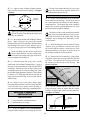
q 8) Remove the stabilizer from the fuselage. Using the lines you just drew as a guide, carefully remove the covering from between them using a modeling knife. See photo # 11 below.
Photo # 11
Remove
Covering
q 5) Install the wing onto the fuselage. Align the
centerline drawn on the top and the rear of the stabilizer with the centerline marks drawn on the fuselage.
When those are aligned, hold the stabilizer in that position using masking tape. Align the horizontal stabilizer with the wing. When viewed from the rear,
the horizontal stabilizer should be level with the wing.
If it is not level, use 220 grit sandpaper with a sanding block and sand down the high side of the stabilizer mounting platform until the proper alignment is
achieved. The tips of the stabilizer should also be
equal distance from the tips of the wing. See figures
# 4 and # 5 below.
Figure # 4
A
A-1
A = A-1
Figure # 5
B = B-1
Draw Line
Draw Line
When cutting through the covering to remove
it, cut with only enough pressure to only cut
through the covering itself. Cutting into the balsa
structure may weaken it.
q 9) When you are sure that everything is aligned
correctly, mix up a generous amount of Kwik Bond 5
Minute Epoxy. Apply a thin layer to the bottom of
the mounting area on the bottom of the stabilizer and
to the top of the stabilizer mounting platform on the
fuselage. Set the stabilizer in place and realign.
Double check all of your measurements once more
before the epoxy cures. Hold the stabilizer in place
with masking tape and remove any excess epoxy using a paper towel and rubbing alcohol.
HINGING THE ELEVATOR
q 10) Remove the three plastic hinges from the elevator. Using 220 grit sandpaper, lightly sand the top
and bottom of each half of all three hinges.
B
B-1
Lightly sanding the hinge's gluing surfaces will
roughen the plastic increasing the bonding
strength between the epoxy and the hinge.
13
q 11) Apply a couple of drops of lightweight machine oil to the pivot point of each hinge. See figure
# 6 below.
The top of the rudder should be as close to the
tip of the vertical fin as possible without actually rubbing the bottom of the tip.
Figure # 6
ALIGNING THE VERTICAL STABILIZER
Apply Oil to
Pivot Point
Hinge
Applying oil to the pivot point of the hinges will
prevent the epoxy from gluing the hinges solid
when they are installed.
q 12) Mix a small amount of Kwik Bond 5 Minute
Epoxy. Apply a thin layer of epoxy to the top and
bottom of only one half of each hinge. Slide the hinges
into the hinge slots in the elevator. Remove any excess epoxy using a paper towel and rubbing alcohol.
Insert each hinge into the elevator so the pivot
point is about halfway into the leading edge.
This will result in the proper hinge gap when the elevator is hinged to the stabilizer.
q 13) After the epoxy has set up, mix a second
small batch of Kwik Bond 5 Minute Epoxy. Apply a
thin layer to the top and bottom of the exposed half of
each hinge. Slide the elevator in place, making sure
each hinge slides into it's respective hinge slot. Push
the elevator firmly against the stabilizer. There should
be about a 1/32” hinge gap and there should also be
equal space between the tips of the elevator and the
stabilizer tips.
q 14) Remove any excess epoxy using a paper
towel and rubbing alcohol. Once the epoxy has fully
cured, any other excess epoxy can be carefully removed from the hinge joint using a modeling knife.
VERTICAL STABILIZER
INSTALLATION
q 2) Set the vertical stabilizer on top of the horizontal stabilizer and fuselage. The tab at the rear of
the vertical stabilizer fits in the precut slot in the horizontal stabilizer. The bottom edge of the stabilizer
should also be firmly pushed against the top of the
horizontal stabilizer and the fuselage.
The bottom of the rudder should not touch the
top of the horizontal stabilizer. If it does, carefully sand the bottom of the rudder using 220 grit
sandpaper with a sanding block until there is sufficient clearance.
q 3) While holding the vertical stabilizer firmly
in place, use a pen and draw a line on each side of
the vertical stabilizer where it meets the top of the
horizontal stabilizer. Also draw an outline on top of
the fuselage around the vertical stabilizer.
q 4) Remove the vertical stabilizer. Using a modeling knife, remove the covering from below the lines
you drew. Also remove the covering from inside
the outline you drew on top of the fuselage. See
photo # 12 below.
Photo # 12
Draw Outline
Remove
Covering
(Vertical Stabilizer
Shown in Box)
Remove
Covering
q 5) Set the vertical stabilizer back into place.
Using a triangle, check to ensure that the vertical
stabilizer is aligned 90º to the horizontal stabilizer.
See figure # 7 below.
Figure # 7
PARTS REQUIRED
90º
Vertical
Stabilizer
q {1} Vertical Stabilizer w/Rudder & Hinges
q {1} Molded Plastic Tail Fairing
HINGING THE RUDDER
Horizontal
Stabilizer
q 1) Hinge the rudder to the vertical stabilizer
using the same technique used to hinge the elevator.
14
Fuselage
MOUNTING THE VERTICAL STABILIZER
q 6) When you are sure that everything is aligned
correctly, mix up a generous amount of Kwik Bond
5 Minute Epoxy. Apply a generous layer to the slot
in the horizontal stabilizer and to the entire bottom
surface of the vertical stabilizer. Set the stabilizer
in place and realign. Double check all of your measurements once more before the epoxy cures. Hold
the stabilizer in place with masking tape and remove
any excess epoxy using a paper towel and rubbing
alcohol. Allow the epoxy to fully cure before proceeding. See photo # 13 below.
Photo # 13
You may find that the sides of the fairing extend beyond the trailing edge of the vertical stabilizer. Use a modeling knife and cut the sides of the
fairing so they are flush with the trailing edge of the
vertical stabilizer before installing the fairing.
q 10) When satisfied with the fit, remove the fairing and lightly sand the inside surfaces that will be
glued to the fuselage, horizontal stabilizer and vertical stabilizer using 220 grit sandpaper.
q 11) Using a ruler and a pen, measure and mark
the location of the rudder pushrod exit slot onto the
plastic fairing.
q 12) Using a modeling knife, cut the slot in the
fairing to match the slot precut in the fuselage. See
photo # 15 below.
Photo # 15
INSTALLING THE TAIL FAIRING
q 7) Using a modeling knife, carefully cut out
the molded plastic tail fairing leaving 1/4” of material around the entire perimeter to use as a gluing
surface. Also remove the material from the top of
the fairing so it can slide around the vertical stabilizer. See photo # 14 below.
Photo # 14
Cut Slot
q 13) Slide the fairing back into place. Double
check the placement of the slot and make any adjustments necessary. While holding the fairing firmly
in place, carefully trace around it using a pen.
q 14) Using a modeling knife, carefully remove
the covering from inside the outline.
Tail Fairing
Remove for
Vertical Stabilizer
Leave 1/4”
of Material
q 8) Using a modeling knife, remove the covering from over the precut rudder pushrod exit slot in
the top of the fuselage. The slot is located on the
right top side of the fuselage (looking from the rear),
3-3/4” in front of the rudder hinge line. The slot is
3/4” long and 1/8” wide.
q 9) Trial fit the tail fairing in place. It should fit
tightly around the fuselage and the front and sides of
the vertical stabilizer. Use a modeling knife and 220
grit sandpaper to make any necessary adjustments to
obtain the proper fit.
15
q 15) Mix a small amount of Kwik Bond 5
Minute Epoxy and apply a thin layer to the gluing
surfaces of the fairing. Slide the fairing into place
and remove any excess epoxy using a paper towel
and rubbing alcohol. Hold the fairing in place using
pieces of masking tape until the epoxy fully cures.
See photo # 16 below.
Photo # 16
SERVO INSTALLATION
Photo # 18
PARTS REQUIRED
Rudder
Servo
Elevator
Servo
q {1} Servo Tray
q {1} Servo Tray Support
Output
Shaft
INSTALLING THE SERVO TRAY
q 1) Test fit the servo tray and the servo tray support into the fuselage. The support is installed into
the two precut notches in the bottom of the fuselage
sides. The servo tray fits into the corresponding
notches in the support and the rear bulkhead. See
photo # 17 below.
Because the size of servos differ, you may need
to adjust the size of the precut opening in the
servo tray to fit your servos. If so, carefully use a
modeling knife.
Photo # 17
Servo
Tray
Servo Tray
Support
q 5) Install the two servos using the wood screws
provided with your radio system. Drill 1/16” pilot
holes through the servo tray before installing the
screws. This will help prevent the wood from splitting and make it easier to install the screws.
PUSHROD INSTALLATION
PARTS REQUIRED
It may be necessary to sand the edges of the
servo tray and/or servo tray support to obtain a
good fit. If so, use 220 grit sandpaper with a sanding
block. Remove small amounts at a time until a good
fit is obtained.
q 2) When satisfied with the fit, remove the tray
and the support. Mix Kwik Bond 5 Minute Epoxy.
Apply a generous amount of epoxy to the gluing surfaces of the support and the tray. Reinstall the parts
and allow the epoxy to fully cure.
INSTALLING THE SERVOS
q 3) Install the rubber grommets and brass collets
provided with your radio system onto two standard
servos. See figure # 8 below.
Figure # 8
Rubber
Grommet
Servo
Brass
Collet
q 4) Test fit the two servos into the servo tray. The
output shaft in each of the servos should face the
front of the airplane. The servos should be centered
within the mount and as close together as possible.
See photo # 18 at top right.
q
q
q
q
q
q
q
q
q
{2}
{2}
{1}
{1}
{2}
{2}
{4}
{2}
{1}
2mm x 610mm Threaded Pushrods
3mm x 640mm Nylon Pushrod Housings
3mm x 55mm x 14mm Pushrod Support
8mm x 20mm Clear Tubing
Metal Clevises
Nylon Control Horns w/ Backplates
2mm x 15mm Machine Screws
Adjustable Servo Connector Assemblies
Hex Wrench
INSTALLING THE PUSHROD HOUSINGS
q 1) Using a modeling knife, remove the covering from over the precut elevator pushrod exit slot in
the fuselage. The slot is located on the left side of the
fuselage (looking from the rear), 6-1/2” in front of
the elevator hinge line and 3/4” down from the top of
the fuselage. The slot is 3/4” long and 1/8” wide.
q 2) Test fit the nylon pushrod housings into the
fuselage. Insert one housing through the rudder pushrod exit slot and one housing through the elevator
pushrod exit slot.
q 3) Slide the two pushrod housings through the
fuselage and into the servo compartment. Using 220
grit sandpaper, lightly sand the last 1” of each of the
pushrod housings that extends beyond the outside
of the fuselage.
16
q 4) Pull the pushrod housings through the servo
compartment until 1/4” of each housing extends beyond the outside of the pushrod exit slots.
q 5) Mix a small amount of Kwik Bond 5 Minute
Epoxy. Carefully apply a small amount to the ends
of the pushrod housings where they exit the fuselage.
Use enough epoxy to fill any gaps and remove any
excess using a paper towel and rubbing alcohol. Allow the epoxy to fully cure before proceeding. See
photo # 19 below.
Apply Epoxy
to These Joints
Exit Slot
Pushrod
Housing
q 6) Slide one pushrod housing through each of
the outer holes in the plywood pushrod support. Slide
the support over the housings until it is flush with the
rear bulkhead.
The pushrod housings should cross inside the
fuselage. Make sure the elevator pushrod housing exits the right hole in the pushrod support and
that the rudder housing exits the left hole.
q 7) With the pushrod support pushed firmly
against the rear bulkhead, use a modeling knife and
cut off the two housings 1/4” in front of the support.
See photo # 20 below.
Pushrod
Housing
Figure # 9
Control
Horn
Elevator
Backplate
Machine Screw
q 9) When satisfied with the alignment, use a
5/64” drill bit, and the control horn as a guide, and
drill the two mounting holes through the elevator.
Photo # 19
Photo # 20
are directly in-line with the hinge line. The control
horn should also be perpendicular to the hinge line.
See figure # 9 below.
Pushrod
Support
Pushrod
Housing
q 10) Mount the control horn to the elevator by
inserting the two 2mm x 15mm machine screws
through the control horn mounting base, through the
elevator, and into the backplate. Tighten the screws,
but do not overtighten them. You do not want to
crush the wood. See photo # 21 below.
Photo # 21
Elevator
Control
Horn
Hinge
Line
INSTALLING THE RUDDER CONTROL HORN
q 11) The centerline of the rudder control horn
is located on the right side of the rudder (looking
from the rear) 1/2” up from the bottom, at the hinge
line. Position the control horn so the clevis attachment holes are directly in-line with the hinge line.
The control horn should also be parallel with the
top of the fuselage.
Do not install the rudder control horn perpendicular to the hinge line or the pushrod will not
line up when it is installed later. The control horn
should be parallel to the top surface of the fuselage.
INSTALLING THE ELEVATOR CONTROL HORN
q 8) The centerline of the elevator control horn is
located on the bottom left side of the elevator (looking
from the rear) 1-1/8” out from the fuselage side. Position the control horn so the clevis attachment holes
17
q 12) When satisfied with the alignment, use a
5/64” drill bit, and the control horn as a guide, and
drill the two mounting holes through the rudder.
q 13) Mount the control horn to the rudder by inserting the two 2mm x 15mm machine screws
through the control horn mounting base, through the
rudder, and into the backplate. Tighten the screws,
but do not overtighten them. You do not want to
crush the wood. See photo # 22 below.
Photo # 22
q 18) Install one adjustable servo connector
through the second hole out from the center of one
servo arm. Enlarge the hole in the servo arm using
a 5/64” drill bit to accommodate the servo connector. Remove the excess material from the servo arm
using a modeling knife. See figure # 11 below.
Set Screw
Figure # 11
Hinge Line
Connector
Body
Rudder
Servo
Arm
Nut
Control
Horn
INSTALLING THE ELEVATOR PUSHROD
q 14) Slide one threaded pushrod wire into the
elevator pushrod housing from the fuselage side. Note
that the wire has threads on one end of it. Slide the
plain end of the wire into the pushrod housing.
q 15) Using a modeling knife, cut the clear vinyl
tube into two 1/4” long pieces. Slide one piece of
tubing over one metal clevis. See figure # 10 below.
Figure # 10
Clevis
Clear Tubing
This tubing will prevent the clevis from accidentally opening during flight.
q 16) Thread the metal clevis onto the threaded
end of the pushrod wire. For security, thread the clevis on no less than 5/16”.
q 17) Snap the clevis into the third hole out from
the base of the control horn. Move the elevator up
and down with your hand to test for free movement.
See photo # 23 below.
After installing the adjustable servo connector
apply a small drop of Kwik Bond Thick C/A to
the nut. This will prevent the connector from loosening during flight.
q 19) Loosen the set screw in the top of the adjustable connector and slide the servo connector/servo
arm assembly over the plain end of the elevator pushrod wire.
q 20) Use a couple of pieces of masking tape to
hold the elevator in neutral.
q 21) Plug the elevator servo lead into the receiver.
Plug the battery into the motor controller and turn on
the radio system. Center the elevator trim tab on the
transmitter. Place the servo arm onto the servo. The
servo arm should be centered on the servo and point
towards the fuselage side.
q 22) With both the elevator and the servo arm centered, tighten the set screw in the adjustable servo
connector and remove the excess wire using wire cutters. Remove the masking tape from the elevator and
install the servo arm retaining screw in the servo arm.
See photo # 24 below.
Photo # 24
Photo # 23
Tubing
Control
Horn
Pushrod
Housing
Clevis
Pushrod
Wire
18
Pushrod
Wire
Servo
Connector
INSTALLING THE RUDDER PUSHROD
q 23) Slide the second threaded pushrod wire into
the rudder pushrod housing from the top of the fuselage. Note that the wire has threads on one end of it.
Slide the plain end of the wire into the housing.
q 24) Slide the second 1/4” piece of clear vinyl
tubing over the second metal clevis.
q 25) Thread the metal clevis onto the threaded
end of the pushrod wire. For security, thread the clevis on no less than 5/16”.
q 26) Snap the clevis into the first hole out from
the base of the control horn. Move the rudder back
and forth with your hand to test for free movement.
See photo # 25 below.
q 30) Plug the rudder servo lead into the receiver.
Plug the battery into the motor controller and turn on
the radio system. Center the rudder trim tab on the
transmitter. Place the servo arm onto the servo. The
servo arm should be centered on the servo and point
towards the fuselage side.
q 31) With both the rudder and the servo arm centered, tighten the set screw in the adjustable servo
connector and remove the excess wire using wire cutters. Remove the masking tape from the rudder and
install the servo arm retaining screw in the servo arm.
See photo # 26 below.
Photo # 26
Photo # 25
Tubing
Pushrod
Wire
Control
Horn
q 32) While allowing the elevator and rudder
pushrods to stay in their natural positions, push the
plywood pushrod support firmly against the rear
bulkhead.
Clevis
q 27) Install one adjustable servo connector through
the second hole out from the center of one servo arm.
Enlarge the hole in the servo arm using a 5/64” drill bit
to accommodate the servo connector. Remove the excess material from the arm. See figure # 12 below.
Figure # 12
q 33) Glue the pushrod support to the rear bulkhead using Kwik Bond Thick C/A. When the glue
has cured, glue both of the pushrod housings to the
pushrod support. Allow the glue to fully cure.
MOTOR INSTALLATION
Set Screw
PARTS REQUIRED
Connector
Body
q
q
q
q
q
q
Servo
Arm
Nut
After installing the adjustable servo connector
apply a small drop of Kwik Bond Thick C/A to
the nut. This will prevent the connector from loosening during flight.
q 28) Loosen the set screw in the adjustable connector and slide the servo connector/servo arm assembly over the plain end of the rudder pushrod wire.
q 29) Use a couple of pieces of masking tape to
hold the rudder in neutral.
19
{1}
{2}
{2}
{4}
{4}
{4}
Electric Motor
Motor Mount Halves
3mm x 8mm Machine Screws
3mm x 12mm Machine Screws
3mm Flat Washers
3mm Nylon Insert Nuts
INSTALLING THE MOTOR
q 1) Fit the motor to the two metal motor mount
halves. The two halves clamp around the motor and
are held in place using two 3mm x 8mm machine
screws. Do not tighten the motor mount halves completely at this time.
The four mounting tabs on the motor mount
halves should face the back of the motor.
q 2) With the motor loosely in the motor mount,
twist the motor so the wires on the back of the motor
are perpendicular to the mounting tabs on the motor
mount. Slide the motor back so the front edge of the
motor is 3/4” in front of the motor mount halves.
Tighten the two machine screws to hold the motor
securely in place. See photo # 27 below.
Photo # 27
Mounting
Tab
insert nut onto each screw. Tighten the screws completely to hold the motor mount securely in place.
q 8) Using a 1/4” drill bit, carefully drill three
holes through the firewall. These holes should be
located 3/4” up from the bottom of the fuselage. Two
of the holes are located 5/8” in from the fuselage
sides and one hole 1-1/8” from the fuselage side.
See photo # 29 below.
Mounting
Tab
Photo # 29
Motor
Wire
Motor
Wire
Drill
Holes
q 3) Place the motor assembly up against the front
of the firewall. The motor wires and tabs should slide
through the precut slot in the firewall and the motor
mounting tabs should be vertical.
q 4) To properly align the motor, center the motor
from left to right on the firewall. For the proper height,
center the back of the motor in the middle of the precut slot in the firewall. See photo # 28 below.
Photo # 28
Firewall
Machine
Screw
3/
4”
Motor
Mount
Firewall
COWL AND PROPELLER
INSTALLATION
PARTS REQUIRED
q
q
q
q
q
q
q
q
q
q
Motor
It is normal for the motor to be angled down.
The term for this angle is down-thrust. The
Whisper has 5º of down-thrust built into the firewall.
q 5) While holding the motor in position, mark
the locations of the four mounting holes onto the front
of the firewall.
q 6) Remove the motor from the firewall. Using
a 1/8” drill bit, drill four holes through the firewall at
the mounting hole locations.
q 7) Mount the motor to the firewall using four
3mm x 18mm machine screws, four 3mm flat washers and four 3mm nylon insert nuts. Slide the machine screws through the mounting tabs and holes in
the firewall, then install a flat washer and nylon
{2}
{1}
{1}
{2}
{1}
{1}
{1}
{1}
{3}
{4}
Molded Plastic Cowl Halves, Right & Left
Nylon Propeller Hub
Nylon Spinner Cone
Propeller Blade Halves
Tapered Aluminum Hex Adapter
Threaded Adapter
Propeller Washer
Propeller Nut
2mm x 12mm Smooth Shank Machine Screws
2mm x 12mm Wood Screws
JOINING THE COWL HALVES
q 1) Test fit the cowl halves together. One half
has a molded recess that the opposite half glues on to.
When aligned properly the front and back edges of
the cowl should be even and the seam should be flush.
q 2) Hold the cowl halves together using strips of
masking tape taped along the outside of the entire
seam, both on the top and the bottom of the cowl. It
is important that the tape covers the entire seam.
q 3) Using Kwik Bond Thick C/A, glue the cowl
halves together from the inside. To do this properly, run a thin bead of glue along the entire seam
while allowing the glue to seep into the seam and bond
the parts together.
q 4) Allow the glue to thoroughly cure, then remove the masking tape.
20
q 5) Using a modeling knife, carefully cut out the
two molded air ducts in the sides of the cowl. See
photo # 30 below.
q 10) Slide the hub assembly over the threaded
adapter. Install the washer and the propeller nut.
Tighten the nut snug, but do not overtighten it.
Photo # 30
The threaded adapter is machined from lightweight aluminum. Overtightening the propeller nut can damage the adapter.
q 11) Slide the spinner cone over the propeller
blades and onto the hub. Secure it in place by threading one 2mm x 12mm smooth shank machine screw
through the front of the spinner cone and into the
threaded adaptor. Tighten the screw securely, but do
not overtighten.
Remove
Air Duct
(both sides)
INSTALLING THE PROPELLER
q 6) Slide the cowling over the motor, but do not
install it at this time.
q 7) Install the two folding propeller blades onto
the propeller hub using two 2mm x 12mm smooth
shank machine screws. The screws slide through
the larger holes in the hub, through the propeller
blades and thread into the smaller holes in the hub.
See photo # 31 below.
Photo # 31
Propeller
Blade
INSTALLING THE COWL
q 12) Align the front of the cowling with the back
of the spinner. The radius on the cowl should be centered around the radius of the spinner. There should
also be a 1/16” gap between the spinner and the cowl.
It is important that they do not touch. Use masking
tape to hold the cowl firmly in position.
q 13) With the cowl held firmly in position, measure forward 1/8” from the back edge of the cowl
and place four marks to locate the mounting screws.
Two marks are located on each side of the cowl. One
mark should be 3/8” up from the bottom of the cowl
and one mark should be 1-1/2” up from the bottom
of the cowl.
Propeller Hub
Machine
Screw
Do not overtighten the two screws. Overtightening them can cause the propellers not to fold
back properly. Check to make sure they fold easily.
q 8) Insert the tapered hex nut into the propeller
hub. The tapered side of the nut (larger inner diameter) should face the back of the hub.
q 9) Carefully push the threaded adapter onto the
motor shaft. Slide the adapter on until the back edge
of the adapter is flush with the knurls on the motor
shaft. See photo # 32 below.
q 14) Using a 1/16” drill bit, drill four pilot holes
into the cowl and through the fuselage sides at the
four marks made.
q 15) Mount the cowl to the fuselage using four
2mm x 12mm wood screws. Tighten the screws
completely to secure the cowl in place. See photo
# 33 below.
Photo # 33
Photo # 32
Threaded
Adapter
Wood
Screws
(2 ea side)
Motor
Shaft
21
Spinner
Cone
CANOPY INSTALLATION
PARTS REQUIRED
q {1} Molded Plastic Canopy
q {4} 2mm x 12mm Wood Screws
ALIGNING THE CANOPY
q 1) Using a modeling knife, carefully cut out the
canopy along it's molded edges. Remove both of the
ends of the canopy also. See photo # 34 below.
q 7) Install the wing onto the fuselage and set
the canopy back in place. Using a pen, mark where
the canopy needs to be cut to clear the front radius
of the wing.
q 8) Using a modeling knife, cut the canopy at
the mark made. Set the canopy back in place to
check your work. Make any other small adjustments necessary until you are satisfied with the fit.
See photo # 36 below.
Photo # 36
Photo # 34
Canopy
Cut to
Fit Wing
Cut to
Fit Wing
Remove
Material
(Both Ends)
q 2) Set the canopy onto the fuselage. The front
of the canopy has a molded recess in it. Slide this
recess under the back edge of the cowl.
q 9) When satisfied with the fit, remove the
canopy. Using 220 grit sandpaper, carefully sand the
edges of the canopy smooth.
INSTALLING THE CANOPY
q 3) Using a pen, mark the back of the canopy
where it comes in contact with the two front wing
hold down dowels.
q 4) Remove the canopy. Using a modeling knife,
remove the portion of the canopy that you marked.
Reinstall the canopy as before. The back of the canopy
should fit flush against the top of the forward bulkhead. See photo # 35 below.
Photo # 35
q 10) Set the canopy back in place and hold it securely to the fuselage using pieces of masking tape.
q 11) Using a pen, mark the locations of the four
mounting holes. Two holes are located on each side
of the canopy. Place two marks 1/8” up from the bottom edge of the canopy. One of the marks should be
1/2” behind the back edge of the cowl and the second
mark should be 4” behind the back edge of the cowl.
q 12) Using a 1/6” drill bit, drill four holes into
the canopy and through the fuselage sides at the four
marks made.
Slide Under
Cowl
q 13) Remove the masking tape and secure the
canopy in place using four 2mm x 12mm wood
screws. See photo # 37 below.
Cut Out
Around Dowel
Photo # 37
q 5) While holding the canopy firmly in place,
make marks where the sides of the canopy meet the
recessed groove in each side of the fuselage.
Mounting
Screws
(2 ea side)
q 6) Remove the canopy. Use a modeling knife
and a straight edge ruler to carefully cut off the canopy
at the marks made.
22
LANDING SKID INSTALLATION
FINAL ASSEMBLY
PARTS REQUIRED
INSTALLING THE RECEIVER
q {1} Molded Landing Skid
INSTALLING THE LANDING SKID
q 1) Using a modeling knife, carefully cut out the
plastic landing skid. Leave about 1/8” of material
around the base of the skid to use as a gluing surface.
q 2) Test fit the skid onto the bottom of the fuselage. The skid should be centered from side to side
and the front of it should fit just behind the back edge
of the cowling.
q 1) Install the receiver in front of the servo tray.
Use a scrap piece of wood laid over the receiver and
glued to the fuselage sides to hold the receiver securely in place.
q 2) Using a 1/16” drill bit, drill a hole through the
side of the fuselage, near the receiver, for the antenna
to exit. Route the antenna out of the fuselage and secure it to the vertical stabilizer using a rubber band and
a modified servo arm. See figure # 13 below.
Figure # 13
q 3) Using 220 grit sandpaper, lightly sand the
bottom surface of the skid.
q 4) Glue the skid in place using Kwik Bond Thick
C/A. Hold the skid in place until the glue fully cures.
See photo # 38 below.
Cut
Servo Arm
Rubber
Band
Antenna
To Vertical
Fin
Modified
Servo Arm
Photo # 38
INSTALLING THE SWITCH
Landing
Skid
q 3) Plug the servo leads and the switch lead into
the receiver.
Cowl
q 4) The switch should be mounted on the fuselage side, close enough to the receiver so the lead will
reach. Use the faceplate of the switch itself to locate
and mark the switch cutout and mounting holes.
q 5) Using a ruler and a pen, measure back and
place two marks on the bottom of the fuselage 7-1/2”
behind the back edge of the cowling. Center the two
marks between the fuselage sides and the landing skid.
q 6) Using a modeling knife, carefully cut two
1/2” diameter holes at the two marks made. See
photo # 39 below.
Photo # 39
q 5) Cut out the switch hole using a modeling
knife. Use a 5/64” drill bit and drill out the two mounting holes through the fuselage side.
q 6) Secure the switch in place using the two machine screws provided with the radio system.
INSTALLING THE BATTERY AND E.S.C.
q 7) Connect the plug on the motor controller to
the plug on the motor. Connect the motor controller
to the receiver. Place it in the fuselage so it will easily reach the flight battery without putting any strain
on the other wires.
Cut Hole
Landing
Skid
Cut Hole
These two holes are air exit holes that allow hot
air to flow out of the fuselage after it has passed
over the motor and the battery pack.
23
q 8) Install the flight battery in the fuselage. It
rests in the two preinstalled bulkheads in the forward
section under the wing. The battery can be removed
and installed by removing the canopy or the wing.
BALANCING
q 1) It is critical that the Whisper be balanced correctly. Improper balance will cause your plane to lose
control and crash. The center of gravity is located
2-3/8” back from the leading edge of the wing, at
the fuselage sides. This location is recommended
for initial test flying and trimming. There is a 3/8”
margin forward and aft, but it is not recommended
that the center of gravity be located any further back
than 2-3/4”.
q 2) Turn on the radio system. With the trim tabs
on the transmitter in neutral, center the control surfaces by making adjustments to the clevises or adjustable servo connectors. The servo arms should be
centered also.
q 3) When the elevator and rudder control surfaces are centered, move the control stick to the full
deflection for each control surface. Use a ruler and
check the amount of the control throw. The control
throws should be measured at the widest point of
each surface!
q 2) Mount the wing securely to the fuselage using six # 64 rubber bands per side. Using a couple of
pieces of masking tape, place them on the bottom side
of the wing 2-3/8” back from the leading edge, at the
fuselage sides.
INITIAL FLYING/TRAINING
Elevator:
Rudder:
3/8” up
5/8” right
3/8” down
5/8” left
ACCOMPLISHED PILOT
q 3) Place your fingers on the masking tape and
carefully lift the plane.
q 4) If the nose of the plane falls, the plane is nose
heavy. To correct this slide the flight battery further
back in the fuselage. If the tail of the plane falls, the
plane is tail heavy. To correct this, slide the flight
battery forward in the fuselage.
Once you have flown and become familiar with
the flight characteristics of the Whisper, the balance point can be moved forward or aft to change the
flight characteristics. Moving the balance point back
will cause the Whisper to be more responsive, but less
stable and increase the stall speed. Moving the balance point forward will cause the Whisper to be more
stable, but the control sensitivity will be sluggish. Once
you find the optimum center of gravity, we suggest
placing a mark on the battery pack, next to one of the
bulkheads. This way you will be able to install the
battery pack in the proper location every time.
CONTROL THROWS
q 1) We highly recommend setting up the Whisper using the control throws listed. We have listed
control throws for both initial test flying/training and
for the accomplished pilot. If this is your first airplane, please set the control throws according to the
training settings. These settings allow the airplane to
fly smoother and make it easier to control.
Elevator:
Rudder:
5/8” up
7/8” right
5/8” down
7/8” left
Do not use the accomplished pilot settings
for initial test flying or training.
By moving the position of the clevis at the control horn toward the outermost hole, you will
decrease the amount of throw of that control surface.
Moving the clevis toward the control surface will increase the amount of throw.
FLIGHT PREPARATION
q 1) Check the operation and direction of the
elevator, rudder and throttle.
q A) Turn your radio system on.
**CAUTION** Do not turn the receiver on unless
the transmitter is turned on first. Always turn the
transmitter on first. NEVER allow hands or clothing
to get in the way of the propeller when the radio is
turned on. Sudden unwanted radio signals or turning
the radio on with the throttle lever set at full throttle
can turn on the motor unintentionally. Always make
sure the throttle lever is set to off before turning on
the transmitter.
q B) Check the elevator first. Pull back on
the elevator stick. The elevator should move up. If it
does not, flip the servo reversing switch on your
transmitter to change the direction.
24
q C) Check the rudder. Looking from behind
the airplane, move the rudder stick to the right. The
rudder should move to the right. If it does not, flip
the servo reversing switch on your transmitter to
change the direction.
q D) Check the throttle. Moving the throttle
stick forward should turn on the motor.
q 2) Check Control Surface Throw.
q A) The Rudder should move 5/8” left and
5/8” right from center. If it moves too far, move the
pushrod clevis to a hole in the rudder control horn
away from the rudder. Do the opposite if there is
not enough throw.
q B) The elevator should move 3/8” up and
3/8” down from center. If it moves too far, move the
pushrod clevis to a hole in the elevator control horn
away from the elevator. Do the opposite if there is
not enough throw.
PREFLIGHT CHECK
q 1) If you did not yet break in the motor, refer to
page # 6 and follow the instructions for motor breakin. Correct break-in will result in higher performance
and longer motor life. It is highly recommended.
q 2) Cycle the motor battery three times. Nicad
batteries, when new, need to be used 2-3 times before
they produce their top voltage and duration. Simply
charge the battery and then run the motor until the
motor stops. Allow the battery and motor to cool,
then repeat this procedure two more times.
q 3) Check every nut and bolt and every glue joint
in the Whisper to ensure everything is tight and well
bonded. This should include all of the control surface hinges as well.
q 4) Double check the balance of the airplane.
q 5) Check the control surfaces. All should move
in the correct direction and not bind in any way.
q 6) Check the receiver antenna. It should be fully
extended and not coiled up inside the fuselage.
25
q 7) Check the condition of the transmitter batteries. They should be fully charged if they are rechargeable type Nicads, or replaced if they are nonrechargeable cells and the voltage indicator drops out
of the green.
ABC's OF FLYING
If you've come this far, now you're ready to prepare
for the maiden voyage of your new Whisper. Before
proceeding, we highly recommend double checking
all of your work. Make sure there is no detail you
missed and that you understand all of the airplane's
functions. Taking time right now to do this will make
your first few flights much more enjoyable. We hope
you find the following sections helpful, making your
first few flights successful.
Since you've chosen the Whisper, you've avoided
making the most common mistake beginners make:
choosing a high performance aircraft like a P-51D
Mustang or an F-16 Jet as a trainer. Just as you
wouldn't learn to drive a car using an Indy car, learning to fly R/C aircraft should start in a trainer. The
second mistake new pilots make is not seeking out
the help of an experienced modeler. While it is certainly true that some people have learned to fly without help, having the help of an experienced R/C
model pilot will help make those first few flights
more successful. So, we highly recommend seeking out a club or a flying field near you. You'd be
surprised just how many clubs that help beginners
all over the world!
Once at the field, even before removing your plane
from the car, introduce yourself to some of the other
pilots. Find out what safety procedures and frequency
control system is in place. In short, learn and follow
the field etiquette. Doing so will ensure safe modeling for you and others as well as give you a chance to
meet the other flyers and find out who might be the
right person to help you learn to fly.
Sometimes, it is just impossible to find anyone to help.
In that case it would be wise to seek out some additional information about flying R/C. R/C Modeler
Magazine, Harry Higley Models and Model Airplane
News Magazine all publish very good basic flight
training books that will explain flying in more detail.
You may also wish to seek out a computer simulator.
Great Planes and Dave Brown both make excellent
flight simulators that can be very effective at teaching the basic coordination of R/C flight.
If you decide you have no choice but to learn to fly on
your own, choosing the right place to fly your Whisper is of the utmost importance. Select your potential
flying field with the following considerations:
Pi
tch
Yaw
1) Look for a site that has a soft landing area. The
best sites are large grassy fields.
2) The fewer the ground obstructions the better. No
trees, buildings or large rocks should be nearby.
Ro
ll
3) No people or houses should be nearby. While
R/C flying is generally safe, it can lead to harm or
injury. Do not try to fly your model if there are houses
or people nearby.
Choosing the Whisper greatly simplifies these activities. First, it takes very little thrust to overcome the
drag. So much so that the Whisper will glide and
thermal without any motor power at all.
4) There should be no high-lines, telephone lines or
electrical lines anywhere near where you are flying.
If your plane accidentally does fly into wires of any
kind, do not try to retrieve it yourself. Serious injury
or even death could result. Contact the local electric
service company or police or fire department to help
you in retrieving your airplane.
Second, the wing is a high lift design that easily overcomes the weight which means that the Whisper can
fly very slowly.
BASICS OF FLIGHT
To begin you should know how your Whisper operates. First, there are four forces operating on a flying
aircraft: Lift, Weight, Thrust and Drag. The motor
will create thrust to overcome the drag. In times when
the engine is off, gravity pulling the plane down can
act as thrust. This is how the Whisper flies when the
motor is shut down. The wing flies through the air as
a result of the thrust and causes lift to overcome the
weight of the aircraft.
Flying the Whisper
Check the controls. Make sure the throttle, elevator
and rudder are all working properly. The flight battery should be fully peak charged and ready to go.
First, let's lay out the basic maneuvers that will make
up your training flights.
1)
2)
3)
4)
5)
6)
Lift
Dr
st
ru
Th
Launching
Climb-out
Level Flight
Standard Turns
Descent
Landing
ag
Weight
Controlling the Whisper
Flying is three dimensional, therefore, all aircraft operate on three axis: roll, yaw and pitch. Roll is the
wing tips raising and lowering. Yaw is the nose moving from right to left. Pitch is seen as the nose moving up and down. Maintaining flight is the act of
overcoming weight and drag with lift and thrust while
properly controlling all three axis.
All flight is based on these few tasks. Here, we've laid
them out in the same order they will be during flight.
Learn these basics and you will soon fly your Whisper
with great success. Now look at each maneuver individually. Before flight, make sure you are completely
familiar with the functions of the transmitter including
all controls and trim tabs.
Launching and climb-out requires that the plane be facing directly into the wind. To launch the airplane, lightly
grasp the fuselage in your hand, between your thumb
and forefingers, just below the wing, at the center of
gravity. Hold the plane at about shoulder level, apply
full power and solidly toss the airplane straight ahead
and level. Do not throw it hard or up at an angle.
26
Fly the airplane level for about 30 feet and allow the
speed to pick up. Use the rudder to keep the Whisper tracking straight. After the Whisper has picked
up some speed, begin a shallow climb-out by applying a small amount of up elevator. Be gentle. You
don't want to overcontrol the airplane. Allow the
plane to climb on its own. Climbing too fast will
cause the plane to pitch up and it will stop flying
(this is called a stall). If this happens, allow the nose
to drop slightly (which will give the airplane more
speed) and then apply a small amount of up elevator
to bring the nose level.
Once the airplane has reached 50 to 100 feet of altitude, it is time to level the plane and then try a turn.
To level the plane, simply move the elevator stick to
neutral. Keep the wings level using the rudder. If
the plane still climbs slightly or turns, adjust the elevator trim tab until the airplane flies straight with
no stick input.
Now try a turn (before the airplane gets too far away).
To turn, apply rudder in the direction you want to
turn until the wing drops about 15 degrees (or the
wing tip is just below the fuselage). As the wing drops,
begin to apply up elevator. Up elevator will maintain
the plane's altitude and will hold it in the turn. To
prevent the plane from turning too steep, as soon as a
good bank is established, release the rudder control.
Use only the elevator to maintain altitude and hold
the plane in the turn. Once it has turned enough, apply opposite rudder to level the wings. As this opposite rudder is applied, slowly release the up elevator.
Now continue level flight, which will be a small series of tiny corrections of elevator and rudder to keep
the plane straight and level. If you lost altitude during the turn, this is a good time to climb out again.
Before the plane gets too far away, try another turn.
Continue making standard turns and keep the airplane
over the flying field.
The next maneuver will be descent. Usually, one pairs
descent with landing, but in fact, most model airplanes
are constantly descending and climbing. Having the
ability to perform a good controlled descent is important. To descend, simply throttle back to turn off
the motor. As the motor is turned off, allow the plane's
nose to drop some.
27
The descent should be gentle, so let the nose drop
about 10 to 20 degrees. Keep the wing level unless a
turn is required. If you must turn, bank as usual to
start the turn but only hold about half of the normal
amount of up elevator you usually hold to maintain a
turn. In doing so, you will not slow the airplane too
much. When you've reached your desired altitude,
level the wings and add throttle as you add some up
elevator to level the plane.
The final maneuver will be landing. For your first
landing, the goal should be to get the plane down anywhere on the field without hitting anything. Landings should always be made into the wind. Usually,
it is easiest to set up for a landing by making a landing approach. The first part of the landing approach
is the descent. Descend going with the wind (opposite of the direction you will be landing). Once you've
descended to an altitude of 30-50 feet, turn into the
wind. At this point level the wings, throttle back until the motor turns off and the propeller folds back
and allow the nose to drop to descend to the ground
without getting too slow. When the plane is about 10
feet off the ground (just above eye level), apply small
amounts of up elevator to slow the descent and to
slow the plane. Remember to keep the wings level.
Now the plane should descend but will seem like the
nose has not dropped much. If the plane doesn't descend, allow the nose to drop a little. Just before the
plane touches down, apply some up elevator to level
the plane with the ground.
Things to avoid
1) Stalling. Stalling is when the air stops flowing
over the wing properly. For the Whisper, this only
happens when the airplane is flying very, very slow.
A stall normally results in the nose dropping rapidly.
If a stall does occur, allow the nose to drop, which
will increase the airspeed, then apply up elevator to
level the plane. Remember to not pull too much up
elevator or the stall may occur again.
2) Radical Turns. Keeping the wings level or making standard turns are big steps in preventing the plane
from getting out of control. If the plane seems too
fast or is getting into too steep a turn, try letting all
the controls go to neutral, then reduce the throttle and
make corrections to level the wings and then level
the plane.
3) Overcontrolling. Most new pilots try to fly like
they are playing a video game. Most likely, you will
never need full stick movement for any correction.
Typically, you will need very little down elevator as
well. Remember to move the stick in only small
amounts at a time. The radio control system you are
using is proportional, meaning the amount you move
the stick is in direct proportion to the amount the control surface moves. Full deflection of the control surfaces is typically reserved for correcting a major mistake or trying an aerobatic maneuver.
Planning the first flight
After reading through the maneuvers, you need to plan
your first flight. For your first flight, pick a day that
is clear and not windy. Too much wind will complicate your first flight. Take the time to envision the
flight path. The flight will, of course, begin with
launching and climb-out. Once a safe altitude has
been reached, make a turn down wind and continue
to climb. Level off at about 100 feet of altitude. Try
to perform a basic figure 8 pattern. Learn to make
small corrections to keep your plane pointed in the
direction you want it to fly. After 3 or 4 minutes,
begin your descent to land. Turn into the wind to
land. If you're first landing gets the plane down in
one piece and it is located somewhere on the flying
field, that is pretty good!
We hope this information will help you make those
first few flights successful.
BASICS OF THERMAL FLYING
The following is intended toward those pilots who
have mastered basic flying with the Whisper. Thermal flying is by far the most difficult aspect of glider
flying, however it can be the most rewarding. The
beautiful thing about the Whisper is because it is electric you have a much better chance of being able to
seek out and locate thermals. For more information
on thermals, check out your local library or the Internet. There are many books and articles available that
detail what thermals are and how they work.
Thermal flying is truly an art and there is a good
amount of luck when you do find the perfect thermal, but there are ways to hone your skills so that
you can become an artist in flying thermals rather
than remaining a hopeful novice who blunders into
them by accident. The following are some keys to
start this process that should help you learn to be a
better thermal pilot.
The first key is to become very familiar with the way
the Whisper flies. The way it responds when entering and exiting lift is essential. These are things you
will notice as you fly the Whisper more and more.
You need to be familiar with the plane so that you
recognize when it is flying normally and when it is
responding to up or down air. A new plane is very
hard for the novice to tell what is happening in regards to the air. He or she is uncertain if the movement is due to something the pilot did or due to air
movement. You want the plane to be properly
trimmed out so that it flies stable and smooth and to
know how it responds when you turn. Polyhedral
wing designs, like the Whisper, try to remain stable
and are easier for the novice to fly than straight wing
planes (i.e. wings with no dihedral) and, more importantly, are responsive to hitting the side of a thermal
more dramatically than straight wing planes do.
You will seldom hit a thermal straight on in flight.
More often you will hit the side of the thermal and it
will lift one wing more and literally throw your plane
away from the lift. When your plane should otherwise be flying level, watch for a sudden lift of a wing
tip and turn the plane into that area. There is a good
chance that you hit the side of a thermal and it pushed
you away—into the air next to the thermal. If you
power up to fly into the thermal, be careful. You
might fly right through it. Having located a thermal, turn into it and start circling to locate the area
of strongest lift. Tighten up the circle to get the maximum rate of climb.
Think of the air as water. No wind is a calm lake. A
breeze is a slow moving stream and a heavy wind is a
raging river. Often, a pilot hits some lift, starts circling and goes up and up and stays right in the same
spot circling. Then he starts coming down and doesn’t
understand why. On a calm day, once you hit lift you
can circle right there as it isn’t going anywhere but
up. It may die after a short time, but that happens.
With wind, picture your lift as an escalator going
downwind at the same rate as the wind is blowing.
You hit it and start to circle and you go up but you
have to have your circling go downwind at the same
speed as the wind to stay on the escalator. The lift is
moving and if you don’t go with it you lose it.
28
Watch the tail of the airplane bounce up to see if
you are hitting lift. When you fly into a thermal it
kicks the tail up and thus points the nose down.
Despite this “dive” position your plane may actually be going up in the lift. It depends on the strength
of the thermal. That “up tail” is a sign to watch for
in thermal spotting.
Use your visual keys and work on your skills so you
can become accustomed to thermal flying. Don't forget to watch the birds too. If you see birds with their
wings stretched out, circling high above, you can be
sure they are in a thermal. Launch your plane and
head in that direction. They won't mind you joining
them in the fun!
GLOSSARY OF TERMS
Adjustable Connector: Connects to the servo arm.
The pushrod wire passes through the connector and
is held in place with a set screw. The screw can be
loosened to allow the pushrod wire to be adjusted to
the correct length.
C/A Glue: An acronym for Cyanoacrylate. It dries
very fast like "Super Glue". It comes in many different formulas for different uses.
Center of Gravity: Most commonly referred to as
the CG or balance point, it is the point at which the
airplane is in complete balance in all three axis.
Clevis: Part of the control system, either made out of
nylon or metal. It connects the pushrod wire to the
control horn mounted on the control surface.
Clevis Attachment Holes: The molded holes in the
control horn. The clevis attaches to these holes.
Control Horn: Part of the control system, the control horn is mounted to the control surface. It allows
the pushrod to be connected to the control surface.
Most all control horns are adjustable to allow for more
or less control surface movement.
Covering: Material made out of vinyl or polyester.
Covering has heat sensitive adhesive that when heated,
sticks to the wood frame of the airplane. The Whisper uses heat sensitive vinyl covering.
Cycle: The act of fully charging and discharging the
flight battery. Cycling the battery increases performance and duration.
29
Dihedral: The upward angle of each wing half. Dihedral creates more stability that makes learning to
fly much easier.
Dihedral Brace: Made out of plywood, the dihedral
brace strengthens the joint between two wing sections.
Elevator: The elevator is the control surface on the
back of the airplane that moves up and down. This
surface controls pitch.
E.S.C.: Electronic Speed Control. See Motor Controller below.
Epoxy: A two part glue containing a resin and a hardener. Epoxy is available in several drying times and
is stronger than C/A glue. Epoxy is used in high stress
areas such as joining wing halves.
Folding Propeller: The propeller is mounted to the
motor. It turns the with the motor to give the airplane
forward thrust. The propeller on the Whisper folds
back when the motor is off. This allows less drag and
prevents the propeller from breaking during landing.
Hinges: Usually made out of plastic, the hinges connect the control surfaces to the stabilizers or wing.
They pivot allowing the control surface to move.
Horizontal Stabilizer: Mounted in the rear of the
airplane, the stabilizer works with the elevator to control pitch.
Landing Skid: Usually made out of tough plastic,
the landing skid mounts on the bottom of the fuselage to prevent damage to the fuselage during
landing.
Motor Controller: Usually called an electronic speed
control (ESC), the motor controller controls the speed
of the motor. Motor controllers can also be simple on
and off switches.
Output Shaft: The final portion of the output gear.
It's the part the protrudes from the top of the servo.
Peak Charger: A type of battery charger that uses a
microprocessor to sense when your battery is fully
charged (peak charged). Once peak charged, the
charger shuts off so the battery does not overcharge.
Polyhedral Wing: A wing that has dihedral in three
different points on the wing. The Whisper utilizes a
polyhedral wing.
Vertical Stabilizer: Mounted on the rear of the airplane, it works with the rudder to turn the airplane. It
also gives the airplane vertical stability.
Pushrods: Connect between the control surface and
the servo. Transfers the movement of the servo to the
control surface.
Wing Hold Down Dowels: Round pieces of hardwood dowels inserted through the fuselage at the front
and back of the wing. They are anchors for the rubber bands that hold the wing onto the fuselage.
Pushrod Housing: A tube that is usually nylon. The
pushrod wire runs through the housing.
Receiver: The part of the radio system that receives
the signals from the transmitter.
Rudder: The rudder is the control surface on the
back of the airplane that moves right and left. This
works with the polyhedral wing to turn the airplane.
Servo: The part of the radio system that produces
the movement necessary to move the control surfaces.
The servo includes a small motor, gears and a circuit
board to function.
Servo Arm: Connects to the servo, the servo arm
allows the pushrod to connect to the servo.
Servo Reversing: An option on most all new radios, servo reversing allows you to change the direction a servo rotates by just flipping a switch on
the transmitter.
Servo Tray: Usually made out of plywood, the servo
tray is the mounting base for the servos.
Stall Speed: The speed at which air stops moving
fast enough over the surface of a wing to keep the
airplane flying.
Thermal: Simply put, a column of warm or hot air
that rises. Birds and glider pilots enjoy flying in
thermals. Airplanes like the Whisper are specifically
designed to fly in thermals.
Threaded Pushrod: A length of wire that has threads
cut into one end of it. See Pushrods.
Transmitter: The part of the radio system that you
control. It transmits the control inputs to the receiver,
which transfers that information to the servos.
Trim Tab: A sliding tab on the transmitter that allows you make small adjustments to the control surfaces from the transmitter.
Wing Saddle: The portion of the fuselage where the
wing mounts on to.
NOTES
____________________________________________
___________________________________________
_____________________________________________
____________________________________________
_____________________________________________
____________________________________________
____________________________________________
___________________________________________
_____________________________________________
____________________________________________
_____________________________________________
____________________________________________
____________________________________________
___________________________________________
_____________________________________________
____________________________________________
_____________________________________________
____________________________________________
____________________________________________
___________________________________________
_____________________________________________
____________________________________________
_____________________________________________
____________________________________________
____________________________________________
___________________________________________
_____________________________________________
____________________________________________
_____________________________________________
____________________________________________
____________________________________________
___________________________________________
_____________________________________________
____________________________________________
_____________________________________________
____________________________________________
____________________________________________
30
PR
ODUCT EV
ALU
ATION SHEET
RODUCT
EVA
UA
Telling us what you like and don't like determines what model kits we make and how we make them. We
would appreciate it if you would take a few minutes of your time to answer the following questions about
this kit. Simply fold this form on the dotted lines, seal with tape and mail it to us. Do not use staples and
make sure our address faces out.
7) Was any of the assembly difficult for you? If
yes, please explain.
q Yes
q No
_____________________________________
_____________________________________
_____________________________________
_____________________________________
1) Kit: Wattage Whisper Electric Glider
2) Where did you learn about this kit?
q Magazine Ads
q Friend
q Hobby Shop
q Other
q Internet
C u t
A l o n g
D o t t e d
L i n e
3) What influenced you the most to buy this kit?
q Magazine Ads
q Price
q Type of Model
q Box Art
q Recommendation
q Other
q Internet
4) Did you have any trouble understanding the
written instructions? If yes, please explain.
q Yes
q No
_____________________________________
_____________________________________
_____________________________________
_____________________________________
5) Did you have any trouble understanding any of
the photographs. If yes, please explain.
q Yes
q No
_____________________________________
_____________________________________
_____________________________________
_____________________________________
6) Were any of the kit parts:
q Damaged
q Wrong Size
q Missing
q Wrong Shape
If you checked any of the boxes above, did you
contact our Customer Service Department to re
solve the problem?
q Yes
q No
8) What did you like most about this kit?
q Assembly Manual
q Parts Fit
q Hardware Supplied q Price
q Other
_____________________________________
_____________________________________
_____________________________________
9) What did you like least about this kit?
q Assembly Manual
q Parts Fit
q Hardware Supplied q Price
q Other
_____________________________________
_____________________________________
_____________________________________
10) Are you satisfied with the finished model? If
no, please explain.
q Yes
q No
_____________________________________
_____________________________________
_____________________________________
_____________________________________
11) How does this kit compare to similar kits by
other manufacturers?
q Better Than
q As Good
q Not as Good
Additional Comments: _________________________________________________________________
_____________________________________________________________________________________________
_____________________________________________________________________________________
_____________________________________________________________________________________
_____________________________________________________________________________________
31
Fold along dotted line
Post Office
will not
deliver
without
proper
postage
Global Hobby Distributors
Attn: Wattage Customer Care
18480 Bandilier Circle
Fountain Valley, CA. 92728
Fold along dotted line
32