1
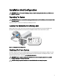
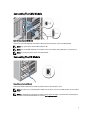
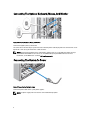
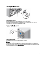
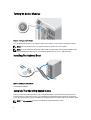
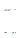
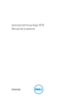
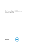
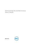
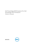
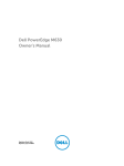
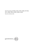
Dell PowerEdge VRTX, M820, M620, and M520
Getting Started Guide
Regulatory Model: E22S, HHB, and FHB
Regulatory Type: E22S001, HHB, and FHB007 Series
Notes, Cautions, and Warnings
NOTE: A NOTE indicates important information that helps you make better use of your computer.
CAUTION: A CAUTION indicates either potential damage to hardware or loss of data and tells you how to avoid the
problem.
WARNING: A WARNING indicates a potential for property damage, personal injury, or death.
Copyright © 2014 Dell Inc. All rights reserved. This product is protected by U.S. and international copyright and intellectual property
laws. Dell™ and the Dell logo are trademarks of Dell Inc. in the United States and/or other jurisdictions. All other marks and names
mentioned herein may be trademarks of their respective companies.
2014 - 01
Rev. A00
Installation And Configuration
WARNING: Before performing the following procedure, review the safety instructions that came with the server
module or enclosure.
Unpacking The System
WARNING: Whenever you need to lift the system, get others to assist you. To avoid injury, do not attempt to lift the
system by yourself.
Unpack the enclosure and the server module(s) and identify each item.
Locating The System Electrical Rating Label
Before setting up the system, make sure you read the electrical rating information for the system provided on the
information tag. The information tag also contains the worldwide regulatory agency marks for the system.
Figure 1. Locating the Electrical Rating Label
Stabilizing The Tower System
The tower system has four feet on its bottom panel that can be extended outward to help properly stabilize the system.
You can also replace the system feet with the optional wheels. For more information on installing the wheels, see the
Dell PowerEdge VRTX Owner's Manual at dell.com/poweredgemanuals.
WARNING: Failure to extend the system feet outward poses the risk of having the system tip over, possibly
causing bodily injury or damage to the system.
CAUTION: Rolling the system on its wheels can cause vibrations that can damage the system.
3
Figure 2. Extending the Feet of the Tower System
Optional — Rack Configuration
If you are using the optional rack configuration, assemble the rails and install the system in the rack following the safety
instructions and the rack installation instructions provided with your system.
NOTE: For more information on converting the system to rack mode, see the Dell PowerEdge VRTX Owner's
Manual at dell.com/poweredgemanuals.
Installing A Server Module
CAUTION: Install a blank in all empty server slots to maintain proper thermal conditions.
NOTE: The enclosure only supports Dell PowerEdge M520, M620, and M820 server modules that are specifically
configured for the enclosure, and can be identified by a label marked PCIe on the server module. If you install
PowerEdge M520, M620, or M820 server modules that are not configured for the enclosure, an error message is
displayed. For more information on configuring a server module for the enclosure, see the Dell PowerEdge VRTX
Owner's Manual at dell.com/poweredgemanuals.
NOTE: To install the M820 full-height server module(s), you must remove the server module partitions. For more
information, see the Owner’s Manual.
Figure 3. Installing a Server Module
Beginning with slot 1, slide the server modules into the enclosure. When a server module is securely installed, its handle
returns to the closed position.
4
Connecting The CMC Module
Figure 4. Connecting the CMC Module
Connect the serial cable (optional) and network cable(s) from the management system to the CMC module.
NOTE: Your system comes with the CMC installed in slot 1.
NOTE: If the second CMC (optional) is not installed, connect the network cable to CMC port 1 on the enclosure.
NOTE: The serial port connects to the active CMC module.
Connecting The I/O Module
Figure 5. Connecting the I/O Module
Connect the network cable to the I/O module to provide network connection to the server.
NOTE: If you have a pass-through module installed in the enclosure, each server module requires its own network
cable.
NOTE: For information on configuring the network settings for the I/O module, see the Dell Chassis Management
Controller for Dell PowerEdge VRTX User’s Guide at dell.com/esmmanuals.
5
Connecting The Optional Keyboard, Mouse, And Monitor
Figure 6. Connecting Keyboard, Mouse, and Monitor
Connect the keyboard, mouse, and monitor.
The connectors on the front of your system have icons indicating which cable to plug into each connector. Be sure to
tighten the screws (if any) on the monitor's cable connector.
NOTE: Connecting the keyboard, mouse, and monitor is optional. You can use the LCD menu options to map a
server module to the KVM. You can also access the KVM remotely using the iDRAC interface. For more
information, see the iDRAC User's Guide at dell.com/esmmanuals.
Connecting The System To Power
Figure 7. Connecting the System to Power
Connect the power cables to the system power supplies.
NOTE: The power supply units must have the same maximum output power.
6
Securing The Power Cable
Figure 8. Securing the Power Cable
Bend the system power cable, as shown in the illustration, and attach to the cable strap.
Plug the other end of the power cable into a grounded electrical outlet or a separate power source, such as an
uninterruptible power supply (UPS) or a power distribution unit (PDU).
Turning On The Enclosure
Figure 9. Turning on the Enclosure
Press the power button on the enclosure. The power indicator should light.
NOTE: The CMC may take a few minutes to initialize after you turn on the enclosure.
Log in to the CMC web page using the CMC IP address displayed in the LCD panel. Configure the I/O module, and map
the virtual adapters and PCIe slots to the server slots. For more information, see the Dell Chassis Management Controller
for Dell PowerEdge VRTX User’s Guide at dell.com/esmmanuals.
7
Turning On Server Modules
Figure 10. Turning on a Server Module
Press the power button on each server module, or power on the modules using the systems management software.
NOTE: Make sure that the enclosure is powered on before you power on the server modules.
NOTE: The server modules do not power on until the CMC is properly configured and has fully initialized. It may
take an additional two minutes for the server iDRAC to initialize after the chassis is fully powered on.
Installing The Optional Bezel
Figure 11. Installing the Optional Bezel
Install the bezel (optional).
Complete The Operating System Setup
If you purchased a preinstalled operating system, see the documentation associated with the operating system. To
install an operating system for the first time, see the installation and configuration documentation for your operating
system. Be sure the operating system is installed before installing hardware or software not purchased with the system.
NOTE: See dell.com/support for the latest information on supported operating systems.
8
Dell Software License Agreement
Before using your system, read the Dell Software License Agreement that came with your system. You must consider
any media of Dell-installed software as BACKUP copies of the software installed on your system’s hard drive. If you do
not accept the terms of the agreement, call the customer assistance telephone number. For customers in the United
States, call 800-WWW-DELL (800-999-3355). For customers outside the United States, see dell.com/support and select
your country or region from the top left of the page.
Related Documentation
WARNING: See the safety and regulatory information that shipped with your system. Warranty information may be
included within this document or as a separate document.
•
The Dell PowerEdge VRTX Owner’s Manual provides information about system features and describes how to
troubleshoot the system and install or replace system components. This document is available online at dell.com/
poweredgemanuals.
•
The Dell Chassis Management Controller for Dell PowerEdge VRTX User’s Guide provides information on installing,
configuring and using the Chassis Management Controller (CMC). This document is available online at dell.com/
esmmanuals.
•
The Integrated Dell Remote Access Controller (iDRAC) User’s Guide provides information about installation,
configuration and maintenance of the iDRAC on managed systems. This document is available online at dell.com/
esmmanuals.
•
The rack documentation included with your rack solution describes how to install your system into a rack, if
required.
•
Any media that ships with your system that provides documentation and tools for configuring and managing your
system, including those pertaining to the operating system, system management software, system updates, and
system components that you purchased with your system.
NOTE: Always check for updates on dell.com/support/manuals and read the updates first because they often
supersede information in other documents.
NOTE: When upgrading your system, it is recommended that you download and install the latest BIOS, drivers, and
systems management firmware on your system from dell.com/support.
NOM Information
The following information is provided on the device described in this document in compliance with the requirements of
the official Mexican standards (NOM):
Importer:
Dell Inc. de México, S.A. de C.V.
Paseo de la Reforma 2620 -11º Piso
Col. Lomas Altas
11950 México, D.F.
Model number:
E22S
Supply voltage:
100 V CA to 240 V CA
Frequency:
50 Hz/60 Hz
Current consumption:
12 A to 6.5 A (x4)
9
Model number:
HHB
Supply voltage:
12 V CC
Current consumption:
37 A
Model number:
FHB
Supply voltage:
12 V CC
Current consumption:
75 A
Technical Specifications
Power
AC power supply (per power supply unit)
Wattage
1100 W
Connector
IEC C14
Heat dissipation
4100 BTU/hr maximum
NOTE: Heat dissipation is calculated using the
power supply wattage rating.
System Voltage Requirements
100–240 VAC, autoranging, 50/60 Hz
NOTE: This system is also designed to be connected to
IT power systems with a phase to phase voltage not
exceeding 230 V.
Battery
3 V CR2032 Lithium coin cell
Physical — Server Modules
PowerEdge M820
Height
38.5 cm (15.2 inch)
Width
5 cm (2 inch)
Depth
48.6 cm (19.2 inch) with handle closed
50.66 cm (19.92 inch) with handle open
Weight (maximum)
14.5 kg (31.9 lb)
PowerEdge M620
Height
19.23 cm (7.57 inch)
Width
5.03 cm (1.98 inch)
Depth
54.43 cm (21.43 inch) with handle closed
56.49 cm (22.24 inch) with handle open
Weight (maximum)
7.0 kg (15.42 lb)
PowerEdge M520
Height
10
19.23 cm (7.57 inch)
Physical — Server Modules
Width
5.03 cm (1.98 inch)
Depth
54.43 cm (21.43 inch) with handle closed
56.49 cm (22.24 inch) with handle open
Weight (maximum)
5.50 kg (12.11 lb)
NOTE: For additional specifications, see the server module's Owner's Manual at dell.com/poweredgemanuals.
Physical — Enclosure
Tower Configuration
Height
48.44 cm (19.07 inch) with system feet
46.38 (cm) (18.26 inch) without system feet
Width
21.92 cm (8.62 inch) without system feet
30.96 cm (12.18 inch) with system feet opened
Depth
72.98 cm (28.72) with or without bezel
Weight (maximum)
74.79 kg (164.88 lb)
Weight (empty)
31.70 kg (69.70 lb)
Rack Configuration
Height
21.92 cm (8.62 inch)
Width
44.63 cm (17.57 inch) without rack ears
48.24 cm (19.0 inch) with rack ears
Depth
72.98 cm (28.72) with or without bezel
Weight (maximum)
68.72 kg (151.50 lb)
Weight (empty)
24.70 kg (54.45 lb)
NOTE: For additional specifications, see the Dell PowerEdge VRTX Owner's Manual at dell.com/
poweredgemanuals.
Environmental
NOTE: Your system is capable of 40 °C and 45 °C excursion operation for fresh air cooled data centers. For more
information, see the Dell PowerEdge VRTX Owner's Manual at dell.com/poweredgemanuals.
NOTE: For additional information about environmental measurements for specific system configurations, see
dell.com/environmental_datasheets.
Temperature
Maximum Temperature Gradient (Operating and
Storage)
20 °C/h (36 °F/h).
Storage Temperature Limits
–40 °C to 65 °C (–40 °F to 149 °F).
Temperature (Continuous Operation)
11
Environmental
Temperature Ranges (for altitude less than 950 m or
3117 ft)
10 °C to 35 °C (50 °F to 95 °F) with no direct sunlight on
the equipment.
Humidity Percentage Range
10% to 80% Relative Humidity (RH) with 26 °C (78.8 °F)
maximum dew point.
Relative Humidity
Storage
5% to 95% RH with 33 °C (91 °F) maximum dew point.
Atmosphere must be non-condensing at all times.
Maximum Vibration
Operating
0.26 Grms at 5 Hz to 350 Hz (all operation orientations).
Storage
1.88 Grms at 10 Hz to 500 Hz for 15 min (all six sides
tested).
Maximum Shock
Operating
One shock pulse in the positive z axis (one pulse on each
side of the system) of 31 G for 2.6 ms in the operational
orientation.
Storage
Four consecutively executed shock pulses in the positive
and negative y and z axes (one pulse on each side of the
system) of 71 G for up to 2 ms.
Maximum Altitude
Operating
–15.2 m to 3048 m (–50 to 10,000 ft).
Storage
12,000 m (39,370 ft).
Operating Altitude De-rating
Up to 35 °C (95 °F)
Maximum temperature is reduced by 1 °C/300 m (1 °F/547
ft) above 950 m (3,117 ft).
35 °C to 40 °C (95 °F to 104 °F)
Maximum temperature is reduced by 1 °C/175 m (1 °F/319
ft) above 950 m (3,117 ft).
40 °C to 45 °C (104 °F to 113 °F)
Maximum temperature is reduced by 1 °C/125 m (1 °F/228
ft) above 950 m (3,117 ft).
Particulate Contamination
NOTE: This section defines the limits to help avoid IT equipment damage and/or failure from particulates and
gaseous contamination. If it is determined that levels of particulates or gaseous pollution are beyond the limits
specified below and are the reason for the damage and/or failures to your equipment, it may be necessary for you
to re-mediate the environmental conditions that are causing the damage and/or failures. Re-mediation of
environmental conditions will be the responsibility of the customer.
Air Filtration
NOTE: Applies to data center environments only.
Air filtration requirements do not apply to IT
equipment designed to be used outside a data
center, in environments such as an office or
factory floor.
Conductive Dust
12
Data center air filtration as defined by ISO Class 8 per
ISO 14644-1 with a 95% upper confidence limit.
NOTE: Air entering the data center must have
MERV11 or MERV13 filtration.
Air must be free of conductive dust, zinc whiskers, or
other conductive particles.
Environmental
NOTE: Applies to data center and non-data center
environments.
Corrosive Dust
•
NOTE: Applies to data center and non-data center •
environments.
Air must be free of corrosive dust.
Residual dust present in the air must have a
deliquescent point less than 60% relative humidity.
Gaseous Contamination
NOTE: Maximum corrosive contaminant levels measured at ≤50% relative humidity.
Copper Coupon Corrosion Rate
<300 Å/month per Class G1 as defined by ANSI/
ISA71.04-1985.
Silver Coupon Corrosion Rate
<200 Å/month as defined by AHSRAE TC9.9.
13