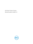
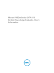
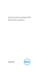
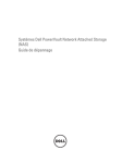
1
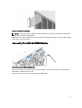
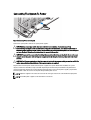
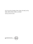
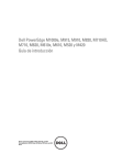
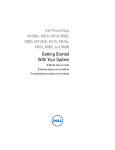
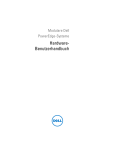
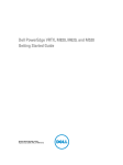
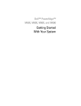
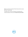
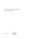
Dell PowerEdge M1000e, M915, M910, M820, M710HD,
M710, M620, M610x, M610, M520, and M420
Getting Started Guide
Regulatory Model: BMX01, DWHH, HHB, FHB, and QHB
Regulatory Type: DWHH Series, HHB Series, FHB Series, and QHB
Series
Notes, Cautions, and Warnings
NOTE: A NOTE indicates important information that helps you make better use of your computer.
CAUTION: A CAUTION indicates either potential damage to hardware or loss of data and tells you how to avoid the
problem.
WARNING: A WARNING indicates a potential for property damage, personal injury, or death.
© 2013 Dell Inc. All Rights Reserved.
Trademarks used in this text: Dell™, the Dell logo, Dell Boomi™, Dell Precision™ , OptiPlex™, Latitude™, PowerEdge™, PowerVault™,
PowerConnect™, OpenManage™, EqualLogic™, Compellent™, KACE™, FlexAddress™, Force10™, Venue™ and Vostro™ are trademarks
of Dell Inc. Intel®, Pentium®, Xeon®, Core® and Celeron® are registered trademarks of Intel Corporation in the U.S. and other countries.
AMD® is a registered trademark and AMD Opteron™, AMD Phenom™ and AMD Sempron™ are trademarks of Advanced Micro
Devices, Inc. Microsoft®, Windows®, Windows Server®, Internet Explorer®, MS-DOS®, Windows Vista® and Active Directory® are
either trademarks or registered trademarks of Microsoft Corporation in the United States and/or other countries. Red Hat® and
Red Hat® Enterprise Linux® are registered trademarks of Red Hat, Inc. in the United States and/or other countries. Novell® and SUSE®
are registered trademarks of Novell Inc. in the United States and other countries. Oracle® is a registered trademark of Oracle
Corporation and/or its affiliates. Citrix®, Xen®, XenServer® and XenMotion® are either registered trademarks or trademarks of Citrix
Systems, Inc. in the United States and/or other countries. VMware®, vMotion®, vCenter®, vCenter SRM™ and vSphere® are registered
trademarks or trademarks of VMware, Inc. in the United States or other countries. IBM® is a registered trademark of International
Business Machines Corporation.
2013 - 09
Rev. A00
Installation And Configuration
WARNING: Before performing the following procedure, review the safety instructions that came with the blade
server or enclosure.
NOTE: The system is intended for restricted access location in accordance with the National Electric Code,
National Standards Institute (ANSI/National Fire Protection Association (NFPA) 70.
Unpacking The System
Unpack your blade server or enclosure and identify each item.
Installing The Enclosure In The Rack
Figure 1. Installing the Enclosure in the Rack
Assemble the rails and install the enclosure in the rack, following the safety instructions and the rail installation
instructions that shipped with the rail kit.
Installing A Sleeve In The Enclosure
NOTE: This procedure applies only to PowerEdge M420.
A sleeve includes up to four quarter-height blades to function as a system. Depending on your order, the sleeve may
ship with the blades preinstalled.
CAUTION: Exercise utmost care when installing or removing the sleeve to prevent damage to the internal
components. To ensure protection for the electronic components inside, follow the Electrostatic Discharge (ESD)
guidelines.
3
Figure 2. Installing a Sleeve
NOTE: Before you install or remove a sleeve from the enclosure, ensure that the top slot of the sleeve (Blade a) is
empty. You can install a blade in the top slot (Blade a) after you install the sleeve in the enclosure.
Remove the orange cover from the sleeve handle. Slide the sleeve into the enclosure and lift the sleeve handle to the top
position to secure the sleeve in the enclosure.
NOTE: To ensure optimal thermal performance, do not replace the cover on the sleeve handle after the sleeve is
installed in the enclosure. Reinstall the cover only if the sleeve is not installed in the enclosure.
Installing A Quarter-Height Blade In A Sleeve
CAUTION: Install a blade blank in all empty blade slots to maintain proper thermal conditions.
Slide the blade into the sleeve and rotate the blade handle upward to secure the blade in the sleeve.
Figure 3. Installing a Quarter-Height Blade
Installing A Full Or Half-Height Blade
CAUTION: Install a blade blank in all empty blade slots to maintain proper thermal conditions.
4
Figure 4. Installing a Half-Height Blade
NOTE: The above figure shows installation of a half-height blade. The procedure for installing a full-height blade is
identical to installing a half-height blade.
Beginning at the top, slide the blades into the enclosure from left to right. When the blade is securely installed, the blade
handle returns to the closed position.
Connecting The CMC And iKVM Modules
Figure 5. Connecting the CMC and iKVM Modules
Connect the serial cable and network cable(s) from the management system to the CMC module. If a second optional
CMC module is installed, connect it as well.
Connect the keyboard, mouse, and monitor to the optional iKVM module.
5
Connecting The System To Power
Figure 6. Connecting Power to the System
Connect the system power cables to the system power supplies.
CAUTION: Many repairs may only be done by a certified service technician. You should only perform
troubleshooting and simple repairs as authorized in your product documentation, or as directed by the online or
telephone service and support team. Damage due to servicing that is not authorized by Dell is not covered by your
warranty. Read and follow the safety instructions that came with the product.
CAUTION: To prevent the power cables from being disconnected accidentally, use the plastic clip on each power
supply to secure the power cable to the power supply, and use the strap to secure the power cable to the strainrelief bar.
CAUTION: For AC power supply, do not plug the power cables directly into a power outlet; you must use a PDU. For
optimal system functionality, a minimum of three power supplies are required.
Plug the other end of the power cables of the AC power supplies into a power distribution unit (PDU). The system
requires a minimum of two PDUs and up to six PDUs depending on the PDU rating. Each PDU must be powered to a
separate appropriate rated branch circuit-protective ground AC power source. For DC power supplies, plug the other
end of the power cables to a branch circuit-protective ground DC power source.
NOTE: All power supplies in the enclosure must be of the same type and have the same maximum output power.
NOTE: AC and DC power supplies cannot be mixed in an enclosure.
6
Turning On The Enclosure
Figure 7. Turning on the Enclosure
Press the power button on the enclosure. The power indicator should light.
Turning On The Blades
Figure 8. Turning on a Blade
Press the power button on each blade, or power on the blades using the systems management software.
Complete The Operating System Setup
If you purchased a preinstalled operating system, see the documentation associated with the operating system. To
install an operating system for the first time, see the installation and configuration documentation for your operating
system. Be sure the operating system is installed before installing hardware or software not purchased with the system.
NOTE: See dell.com/ossupport for the latest information on supported operating systems.
7
Dell Software License Agreement
Before using your system, read the Dell Software License Agreement that came with your system. You must consider
any media of Dell-installed software as BACKUP copies of the software installed on your system’s hard drive. If you do
not accept the terms of the agreement, call the customer assistance telephone number. For customers in the United
States, call 800-WWW-DELL (800-999-3355). For customers outside the United States, see dell.com/support and select
your country or region from the top left of the page.
Related Information
WARNING: See the safety and regulatory information that shipped with your system. Warranty information may be
included within this document or as a separate document.
•
The Owner’s Manual provides information about system features and describes how to troubleshoot the system
and install or replace system components. This document is available online at dell.com/poweredgemanuals.
•
The blade Owner’s Manuals provide information about the blade features and describe how to troubleshoot the
systems and install or replace system components. These documents are available online at dell.com/
poweredgemanuals.
•
For the Owner’s Manuals and Installation Guides for Dell EqualLogic hardware, go to support.equallogic.com.
•
The CMC User's Guide provides information on installing, configuring, and using the CMC. This document is
available online at dell.com/esmmanuals.
•
The Integrated Dell Remote Access Controller (iDRAC) User’s Guide provides information about installation,
configuration and maintenance of iDRAC on managed systems. This document is available online at dell.com/
esmmanuals.
•
The rack documentation included with your rack solution describes how to install your system into a rack, if
required.
•
Any media that ships with your system that provides documentation and tools for configuring and managing your
system, including those pertaining to the operating system, system management software, system updates, and
system components that you purchased with your system.
NOTE: Always check for updates on dell.com/support/manuals and read the updates first because they often
supersede information in other documents.
NOTE: When upgrading your system, it is recommended that you download and install the latest BIOS, drivers, and
systems management firmware on your system from dell.com/support.
Obtaining Technical Assistance
If you do not understand a procedure in this guide or if the system does not perform as expected, see your system
Owner’s Manual. Dell offers comprehensive hardware training and certification. See dell.com/training for more
information. This service may not be offered in all locations.
NOM Information
The following information is provided on the device described in this document in compliance with the requirements of
the official Mexican standards (NOM):
Importer:
8
Dell Inc. de México, S.A. de C.V.
Paseo de la Reforma 2620 -11º Piso
Col. Lomas Altas
11950 México, D.F.
Model number:
BMX01
Supply voltage:
100 V CA to 240 V CA (with 2700 W AC power supply units) or –(48–60) V CC (with
2700 W DC power supply units)
200 V CA to 240 V CA (with 3000 W AC power supply units)
Frequency:
50 Hz/60 Hz or N/A
Current consumption:
16 A (x6) or 75 A (x6)
Model number:
FHB
Supply voltage:
12 V CC
Current consumption:
75 A
Model number:
HHB
Supply voltage:
12 V CC
Current consumption:
37 A
Model number:
QHB
Supply voltage:
12 V CC
Current consumption:
35 A
Technical Specifications
NOTE: For additional specifications, see your system Owner's Manual.
Power — Blades
Coin-cell battery
3 V CR2032 Lithium coin cell
Power — Enclosure
AC/DC power supply (per power supply module) (2700 W)
Wattage
2700 W
Connector
IEC C20
Heat dissipation
1205 BTU/hr (maximum)
Maximum inrush current
Under typical line conditions and over the entire system
ambient operating range, the inrush current may reach
55 A per power supply for 10 ms or less.
AC/DC power supply (per power supply module) (3000 W)
Wattage
3000 W
Connector
IEC 320
9
Power — Enclosure
Heat dissipation
1200 BTU/hr (maximum)
NOTE: Heat dissipation is calculated using the
power supply wattage rating.
Maximum inrush current
Under typical input voltage conditions and over the
entire system ambient operating range, the inrush
current may reach 55 A per power supply for 10 ms or
less.
System Voltage Requirements
16 A, 200 V AC to 240 V AC, 50 Hz/60 Hz (3000 W power
supply)
NOTE: This system is also designed to be connected to
16 A, 100 V AC to 240 V AC, 50 Hz/60 Hz (2700 W power
IT power systems with a phase to phase voltage not
supply)
exceeding 230 V.
DC/DC power supply (per power supply module)
Wattage
2700 W
Connector
Molex # 394260002 at PSU end,
mating connector Molex # 39422-0012
Heat dissipation
1205 BTU/hr (maximum)
Maximum inrush current
Under typical input voltage conditions and over the
entire system ambient operating range, the inrush
current may reach 120 A per power supply for 10 ms or
less.
System Voltage Requirements
75 A, 48 V DC to 60 V DC
NOTE: Heat dissipation is calculated using the power
supply wattage rating.
Physical — Blades
PowerEdge M915
Height
38.5 cm (15.2 inch)
Width
5 cm (2 inch)
Depth
48.6 cm (19.2 inch)
Weight (maximum)
12.7 kg (28 lb)
PowerEdge M910
Height
38.5 cm (15.2 inch)
Width
5 cm (2 inch)
Depth
48.6 cm (19.2 inch)
Weight (maximum)
13.1 kg (29 lb)
PowerEdge M820
10
Height
38.5 cm (15.2 inch)
Width
5 cm (2 inch)
Physical — Blades
Depth
48.6 cm (19.2 inch)
Weight (maximum)
14.5 kg (31.9 lb)
PowerEdge M710 and M610x
Height
38.5 cm (15.2 inch)
Width
5 cm (2 inch)
Depth
48.6 cm (19.2 inch)
Weight (maximum)
11.1 kg (24.5 lb)
PowerEdge M710HD and M620
Height
18.9 cm (7.4 inch)
Width
5 cm (2 inch)
Depth
48.6 cm (19.2 inch)
Weight (maximum)
7.4 kg (16.3 lb)
PowerEdge M610
Height
18.9 cm (7.4 inch)
Width
5 cm (2 inch)
Depth
48.6 cm (19.2 inch)
Weight (maximum)
5.2 kg to 6.4 kg (11.5 lb to 14.0 lb)
PowerEdge M520
Height
18.9 cm (7.4 inch)
Width
5 cm (2 inch)
Depth
48.6 cm (19.2 inch)
Weight (maximum)
6.4 kg (14.1 lb)
PowerEdge M420
Sleeve
Height
39.5 cm (15.6 inch)
Width
5 cm (2 inch)
Depth
44.3 cm (17.4 inch)
Weight
3 kg (6.61 lb)
Blade
Height
9.75 cm (3.8 inch)
Width
5 cm (2 inch)
Depth
45.8 cm (18 inch)
Weight (maximum)
2.3 kg (5.07 lb)
11
Physical — Enclosure
Height
44.0 cm (17.3 inch)
Width
44.7 cm (17.6 inch)
Depth
75.5 cm (29.7 inch)
Weight (maximum)
200.5 kg (442 lb)
Weight (empty)
44.6 kg (98.1 lb)
Environmental
NOTE: For additional information about environmental measurements for specific system configurations, see
dell.com/environmental_datasheets.
Temperature
Maximum Temperature Gradient (Operating and
Storage)
20 °C/h (36 °F/h)
Storage Temperature Limits
–40 °C to 65 °C (–40 °F to 149 °F)
Temperature (Continuous Operation)
Temperature Ranges (for altitude less than 950 m or
3117 ft)
10 °C to 35 °C (50 °F to 95 °F) with no direct sunlight on
the equipment.
Humidity Percentage Range
10% to 80% Relative Humidity with 26 °C (78.8 °F)
maximum dew point.
Relative Humidity
Storage
5% to 95% RH with 33 °C (91 °F) maximum dew point.
Atmosphere must be non-condensing at all times.
Maximum Vibration
Operating
0.26 Grms at 5 Hz to 350 Hz (all operation orientations).
Storage
1.87 Grms at 10 Hz to 500 Hz for 15 min (all six sides
tested).
Maximum Shock
Operating
One shock pulse in the positive z axis of 31 G for 2.6 ms in
all operational orientations.
Storage
Six consecutively executed shock pulses in the positive
and negative x, y, and z axes (one pulse on each side of
the system) of 71 G for up to 2 ms.
Maximum Altitude
Operating
3048 m (10,000 ft).
Storage
12,000 m (39,370 ft).
Operating Altitude De-rating
12
Up to 35 °C (95 °F)
Maximum temperature is reduced by 1 °C/300 m (1 °F/547
ft) above 950 m (3,117 ft).
35 °C to 40 °C (95 °F to 104 °F)
Maximum temperature is reduced by 1 °C/175 m (1 °F/319
ft) above 950 m (3,117 ft).
Environmental
40 °C to 45 °C (104 °F to 113 °F)
Maximum temperature is reduced by 1 °C/125 m (1 °F/228
ft) above 950 m (3,117 ft).
Particulate Contamination
NOTE: This section defines the limits to help avoid IT equipment damage and/or failure from particulates and
gaseous contamination. If it is determined that levels of particulates or gaseous pollution are beyond the limits
specified below and are the reason for the damage and/or failures to your equipment, it may be necessary for you
to re-mediate the environmental conditions that are causing the damage and/or failures. Re-mediation of
environmental conditions will be the responsibility of the customer.
Air Filtration
NOTE: Applies to data center environments only.
Air filtration requirements do not apply to IT
equipment designed to be used outside a data
center, in environments such as an office or
factory floor.
Conductive Dust
NOTE: Applies to data center and non-data center
environments.
Corrosive Dust
NOTE: Applies to data center and non-data center
environments.
Data center air filtration as defined by ISO Class 8 per
ISO 14644-1 with a 95% upper confidence limit.
NOTE: Air entering the data center must have
MERV11 or MERV13 filtration.
Air must be free of conductive dust, zinc whiskers, or
other conductive particles.
•
•
Air must be free of corrosive dust.
Residual dust present in the air must have a
deliquescent point less than 60% relative
humidity.
Gaseous Contamination
NOTE: Maximum corrosive contaminant levels measured at ≤50% relative humidity.
Copper Coupon Corrosion Rate
<300 Å/month per Class G1 as defined by ANSI/
ISA71.04-1985.
Silver Coupon Corrosion Rate
<200 Å/month as defined by AHSRAE TC9.9.
13