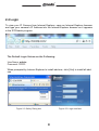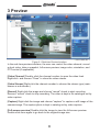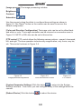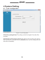
1
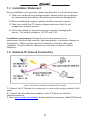
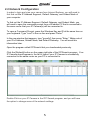
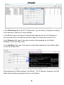
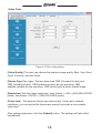
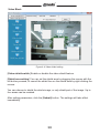
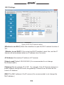
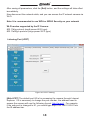
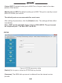
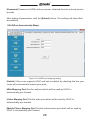
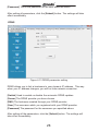
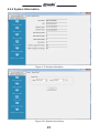
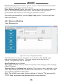
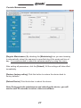
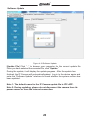
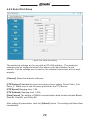
IP Camera User Manual For further help, please visit www.zmodo.com Preface: Dear customer, Thank you for choosing to purchase and use our IP camera products. This series of IP monitoring product is the integrated IP network camera which has been designed for network video surveillance. The series includes a network bullet camera, a network IR bullet camera, and a network dome camera. High performance, monolithic SOC chip is utilized as a media processor which integrates video capture, compression, and transmission. Standard H.264 main profile encoding algorithm ensures clear and smooth video transmission. A n embedded web server allows user to view real-time footage and remotely control the camera via IE web browser. This series of IP camera is well-suited for home and small business, as well as any situation which needs to apply remote network transmission and remote network control. It's easy to install and operate. Product Versions: The content in this manual may be different from the product version you are using. If you meet any problems which can't be solved according to this manual, please contact our technical support or product supplier. The content in this manual will be updated when necessary. Our company reserves the right to update without notice. Intended Reader: This manual is intended for the following personnel: System planner Onsite tech-support and maintenance personnel Administrator for system installation, configuration and maintenance Users for business operation on product functions Terms in this Manual: IP Camera, or IPC in this manual, means network camera including network bullet camera, network dome camera, network PT camera, and network IR camera. Click: Click with left button of mouse. Double-click: Rapidly click the left mouse button twice. Right-click: Click with the right button of mouse. The [ ] symbol indicates the windows name, menu name, or data table; such as [Download Address]. ® Contents 1 Product Introduction. ................................................................................. 2 1.1 Brief Introduction. ....................................................................................... 2 1.2 Main Features. .......................................................................................... 2 1.3 Installation Statement ............................................................................... 3 1.4 Network IP Camera Connection. ...............................................................3 2 Log In. ........................................................................................................... 4 3 Preview .........................................................................................................9 4 System Setting. .........................................................................................11 4.1 Local Configuration...................................................................................11 4.2 Remote Configuration. ............................................................................. 12 4.2.1 Video Setting. ........................................................................................ 12 4.2.2 Network Parameter ............................................................................... 15 4.2.3 Alarm Setting. ........................................................................................ 24 4.2.4 System Information. ............................................................................. 25 4.2.5 Advanced Setting. ................................................................................. 26 4.2.6 Serial Port Setup. ..................................................................................29 5 Appendix. .................................................................................................. 30 1 ® 1 Product Introduction 1.1 Brief Introduction This camera combines a traditional analog camera image sensor with a digital, IP based video stream. The software is built off of an efficient Linux system with all code stored in flash memory. This allows the camera to be small in size and extremely reliable. Figure 1-1 Network IP Camera Figure 1-2 Camera Cable Ports 1.2 Main Features * * * * * * * * * * * * Using only 30W, the camera will provide a 640x480 resolution image at 30 frames per second Using H.264’s advanced video compression standard, the camera is capable of high compression rates and flexible operation. A 1/4’’CMOS sensor provides fluid motion video with high -quality color. Automatic snapshots on alarm One key rescue system Dual stream with smart phone access Build-in web server supports access via Internet Explorer Support multiple user simultaneously, multi-level management ensures high system security. Support motion detection alarm (area, sensitivity configurable) and e-mail alert function Supports online system upgrade through the network and USB. Automatic recovery functions when the system temporarily loses internet connection. Support PPPOE, DDNS, LAN, and Internet (ADSL, Cable Modem) 2 ® 1.3 Installation Statement During installation and operation, please pay attention to the following items: 1. When you received the package product, please check the equipment and accessories according to the packing list inside the shipping box. 2. Before installing the system, please carefully read this manual. 3. When you install the IP Camera, please make sure that it is not plugged into a power source. 4. Check the voltage of the power source to prevent damaging the device. The correct voltage is 12V DC and 1.5A. Installation environment: Please do not use the cameras in an environment that has high humidity, high temperature, or extreme changes in temperature. Make sure the camera is installed in a location with good ventilation. Do not install the camera in an area that is subject to violent vibrations. 1.4 Network IP Camera Connection Figure 1-3 Device Connection of Network IP Camera 1: Connect the IP Camera to an open port in your router using a network LAN cable. 2: Connect the included power adapter to the IP Camera so that the camera powers on. 3: Go to www.zmodo.com/nvrdisc and download the program called IPCSearch. 3 ® 2 Log In When using IE (Internet Explorer) to view the IP camera for the first time, you will have to set the security level for ActiveX controls. 2.1 Set Security Levels Open Internet Explorer, enter the IE Tools menu and go to Tools -->Internet Options --->Security Settings ---->Custom Level. Find the item titled “Download unsigned ActiveX Controls” and change it to “Prompt.” Also change “Initialize and script ActiveX controls not marked as safe for scripting” to “Prompt.” Figure 2-1 Security Level Setting Install ActiveX and plugins: Type the network camera IP address in the IE browser address bar, and press [Enter] to bring up a dialog box to install ActiveX. Click [OK] to install. Note: Do not use Internet Explorer 64-Bit to access the cameras. The ActiveX control is only compatible with the 32-Bit version of Internet Explorer. 4 ® 2.2 Network Configuration In order to login and view your camera from Internet Explorer, you will need to first find out the IP Address Segment, Default Gateway, and Subnet Mask of your computer. To find out the IP Address Segment, Default Gateway, and Subnet Mask, you will need to open the command prompt from a Windows PC that is connected to the same router that your IP Camera(s) will be connected to. To open a Command Prompt, press the Windows Key and R at the same time on your keyboard. Type "cmd" in the run line and press "Enter." In the new window that appears, type "ipconfig" then press "Enter." Make note of your IPv4 Address, Subnet Mask, and Default Gateway. You will need this information later. Open the program called IPCSearch that you downloaded previously. Click the [Refresh] button on the upper right side of the IPCSearch program. Your IP Camera should appear in the list of items if your IP Camera is successfully connected to the same router as your PC is connected to. Double-Click on your IP Camera in the IPC Search program, and you will have the option to change some of the network settings: 5 ® In the Networking tab of the IPC Config menu, you will need to change the settings of the camera to match your router settings: In the IP field, type in the same IP address that appeared as the IPv4 Address on your ipconfig results, but label the last three digits to a larger value such as 101. In the Gateway field, type in the same numbers that appeared as the Default Gateway in your ipconfig results. In the Sub Mask field, type in the same numbers that appeared as the Subnet Mask on your ipconfig results. After adjusting all of these settings, click [Save]. The IP Address, Gateway, and Sub Mask should update immediately after you click [Save] 6 ® 2.3 WiFi Configuration Double click on the IP Camera that you just saved networking settings on, and click on the "Wifi" tab. Select the check box to enable Wi-Fi. Next, manually set the IP Addr field, Subnet Mask field, and Gateway field to match the settings that appear in the Networking tab of the IPC Config menu. Click [Submit] then click [Refresh]. A list of available Wifi networks will appear in the list. Double click the name of the Wifi network to enter the WIFI Wireless Network Settings menu. From this menu, enter your Wifi password and click "Establish Connection." Click "Refresh" on the WIFI Wireless Network Settings menu, your camera should now show Connection Status: Connected. You may need to click "Refresh" more than once before the Connection Status reads: Connected. You have successfully connected one camera to your wireless router using Wifi! You may now disconnect the Ethernet from the camera, and your IP Camera should continue to appear in the IPCSearch program. 7 ® 2.4 Login To view your IP Camera from Internet Explorer, open an Internet Explorer browser and type your camera’s IP Address into the Internet Explorer browser as it appears in the IPCSearch program: The Default Login Values are the Following: UserName: admin Password: 111111 When prompted by Internet Explorer to install add-ons, click [Yes] to install all addons. Figure 2-2 Safety Dialog box Figure 2-3 Login Interface 8 ® 3 Preview Figure 3-1 Real-time Preview Interface In the real-time preview interface, the user can control the video channel, record a short video, take a snapshot, full-screen preview, image color, orientation, and PTZ control (if applicable). [Video Channel] Double -click the channel number to open the video feed. Right-click and choose “Close” to close the video stream. [Video Stream] Right-click the channel number to choose the stream type (mainstream or sub-stream). [Record] Right-click the image and choose “record” check to start recording. Remove “record” check to stop recording. The video is kept in file catalogue set by video capture. [Capture] Right-click the image and choose “capture” to capture a still image of the camera image. The capture photo is kept in catalog set by video capture. [Full-screen preview] Double-click the image to view the full-screen preview. Double-click once again to go back to the original image size. 9 ® [Image process] The image processing includes: Brightness Contrast Saturation Use the mouse to drag the slider to configure these settings as shown in figure 3-2. The “Reset” button on the camera can be used to recover the default configuration. [Color and Direction Configuration] The image color can be set to either black and white or color. The image orientation can be mirrored or reversed as seen in Figure 3-3. NSTC or PAL also can be set in this section. [PTZ control] PTZ control allows the following camera motions: upward, downward, left, and right. The lens operation includes vary magnification, vary focus, vary iris, etc. This control is shown in Figure 3-4. Figure 3-2 Image parameter adjustment Figure 3-3 Color and direction control Figure 3-4 PTZ control [System Parameter Settings] Click this button to enter into the System Settings interface. From here, you can configure many of the settings within the camera. [Reboot Device] Click this button to reboot the device. 10 ® 4 System Setting 4.1 Local Configuration Figure 4-1 Local Configuration [Video files packaged time] This setting controls the length of the video files recorded. [Video/Captured file storage path] Set file path for local recording and capture. After the file path is selected, click the [Submit] button, and the configuration will take effect immediately. 11 ® 4.2 Remote Configuration 4.2.1 Video Setting ·On Screen Display (OSD) control / Character Overlay Figure 4-2 OSD control setting [Title] This is the name of the video channel, and it is displayed on the upper left of the image. The maximum number of characters for this field is 16. Click the check box, and it will display on the screen. Un-check the check box, and it will not display the title on the screen. [Time format] You can choose whether to display title, date and time, and also you can choose the time format. It is recommended to leave it at the default. After setting the date and time, click the [Submit] button, and the setting will take effect immediately. 12 ® ·Video Code Figure 4-3 Video coding setting [Video Quality] The user can choose the desired image quality: Best, Very Good, Good, Common, and Not Good. [Stream Type] Two types: The two options are CBR (Constant bit rate) and VBR (Variable bit rate). CBR enables constant bit rate encoding; VBR enables variable bit rate encoding. CBR should yield a better overall image [Resolution] Sets the image resolution: main stream = VGA = (640×480=307200 pixels), sub stream = QVGA = (320×240=76800 pixels). [Frame rate] This sets the frames per second rate. Under poor network conditions, you can reduce the frames per second to provide a more stable video feed. After setting parameters, click the [Submit] button. The settings will take effect immediately. 13 ® ·Video Block Figure 4-4 Video shield setting [Video shield switch] Enable or disable the video shield feature. [Shield area setting] You can set the shield area by dragging the mouse with the left button pressed, or cancel the shield box on the shield area by right-clicking the mouse. You can choose to shield the whole image, or only shield part of the image. Up to four areas can be masked. After setting parameters, click the [Submit] button. The settings will take effect immediately. 14 ® 4.2.2 Network Parameters ·Wired Settings Figure 4-5 wired network setting [DHCP] If the router allows DHCP functionality, select DHCP to locate an unused IP Address on the router. After the camera is configured and is able to be viewed online, it is recommended to keep DHCP disabled. [IP Address] Set the wired cable IP address of IP camera device. [Subnet mask] Default: 255.255.255.0 (It is recommended to not change the Subnet mask.) [Gateway] Set the gateway IP of IPC. For example, if the IP Camera accesses a public network through the router, the gateway IP needs to be the same as the router’s IP Address. [MAC] The MAC address of the IP camera (It is recommended to not change the MAC address.) [DNS address] If the user has a DDNS account, the DNS address needs to be set to the DNS address of the place to which the device is assigned to in the DNS account. After setting parameters, click the [Submit] button. The settings will take effect immediately. 15 ® ·Wi-Fi Settings Figure 4-6 IPC WI-FI network setting [Whether to use Wi-Fi] Select this checkbox to open the Wi-Fi network function of IPC. [Whether to use DHCP] If the router has DHCP enabled, select this, and the IP camera will automatically obtain an IP address from the router. [IP Address] Set wireless IP address of IP camera. [Subnet mask] Default: 255.255.255.0 (It is recommended to not change the Subnet mask.) [Gateway] Set the gateway IP of IPC. For example, if the IP Camera accesses a public network through the router, the gateway IP needs to be the same as the router’s IP Address. [MAC] The MAC address of the IP camera (It is recommended to not change the MAC address.) 16 ® [DNS address] If the user has a DDNS account, the DNS address needs to be set to the DNS address of the place to which the device is assigned to in the DNS account. [Hotspot Search Results] After enabling Wi-Fi, the camera will automatically search for wireless networks in the area. When the camera is searching for a wireless network you will see the following information listed: the name of the wireless router, signal intensity, and the encryption type. Click on “add hotspot” or double-click on an existing hotspot to open the “Wi-Fi Hotspot Setting” dialog box as the figure below shows: Figure 4-7 Wi-Fi Hotspot setting If this screen was entered by double-clicking an existing hotspot, the hotspot will be assigned automatically. If this screen was entered by clicking “Add hotspot,” then type in the SSID, corresponding encryption mode, and the network password. Click [Establish Connection] to establish a connection with the wireless network. You will be presented with a success or a failure message with the result of this connection. If connected, “Connected” will appear after hotspot name; if not, please click “Refresh” to refresh connection status or click this button to search device again. 17 ® After saving all parameters, click the [Exit] button, and the settings will take effect immediately. Now disconnect the network cable, and you can access the IP network camera via Wi-Fi. Note: It is recommended to use WPA or WPA2 Security on your network Wi-Fi modes supported by the IP Camera: 802.11b/g protocol (small power Wi-Fi type) 802.11a/b/g/n protocol (large power Wi-Fi type) ·Listening Port (LPRT) Figure 4-8 LPRT setting [Web LPRT] The default port 80 is for accessing the camera through Internet Explorer. If it is necessary to change the port number, the address used to access the camera will use the following format: http://ip:port/. For example, if the web port is changed to 81, you would type http://192.168.0.100:81 into the IE address bar. 18 ® [Video LPRT] The default video port is 8000.This is the port used for the video portion of the camera. [Mobile phone LPRT] The default mobile port is 9000. This port is used by a smart phone to access your camera. The default ports are recommended for most users. After setting all parameters, click the [Submit] button. The settings will take effect immediately. Note: LPRT can be selectable from a range of 1024~65535. The port cannot be a duplicate port. The Web LPRT can be 80. ·PPPOE Figure 4-9 PPPOE parameters setting [Switch] Set to open or close the PPPOE dial-up function [Username] The ADSL dial-up account is obtained from the internet service provider. 19 ® [Password] Password of ADSL dial-up account, obtained from the internet service provider After setting all parameters, click the [Submit] button. The settings will take effect immediately. ·UPnP(Port Automatically Maps) Figure 4-10 UNPN port mapping setting [Switch] If the router supports UPnP and has it enabled, by checking this box your router will automatically forward your ports. [Web Mapping Port] Set the web port which will be used by UPnP to automatically port forward. [Video Mapping Port] Set the video port which will be used by UPnP to automatically port forward. [Mobile Phone Mapping Port] Set the mobile phone port which will be used by UPnP to automatically port forward. 20 ® After setting all parameters, click the [Submit] button. The settings will take effect immediately. Note: Port Mapping can be between 1024~65535. You cannot use a duplicate port number ·E-mail Figure 4-11 E-mail parameters setting This is used to set up the e-mail address and related parameter of the alarm e-mail features. [SMTP Server] This is the sender e-mail server address. This address varies by e-mail providers. For example, the SMTP server for Gmail is: smtp.gmail.com [E-mail receiving address] The e-mail address that will receive the e-mail [E-mail sending address] The e-mail address that the message will be coming from. [SMTP password] The login password for sending e-mail address. [E-mail title] This is the title of the e-mail that will be sent. [SMTP Port] This is the SMTP port as specified by your e-mail provider. For example, the SMTP port for Gmail is 465, and SSL needs to be on. 21 ® After setting all parameters, click the [Submit] button. The settings will take effect immediately. Common e-mail server configurations: Gmail E-mail server: SMTP Server: smtp.gmail.com SMTP User name:[email protected] SMTP Port: 465 SSL: Enabled ·FTP Figure 4-12 FTP parameters setting FTP Settings will send snapshots from alarm based recordings to the FTP server specified. [FTP Sever] This is the IP address or HTTP network address of the FTP server. [FTP Port] This is the port of FTP server. The default port is 21. [User] This is the username of the FTP Server. 22 ® [Password] This is the password for the user specified above. After setting all parameters, click the [Submit] button. The settings will take effect immediately. ·DDNS Figure 4-13 DDNS parameter setting DDNS allows you to link a hostname to your dynamic IP address. This way when your IP address changes, you will not lose network connection. [Switch] Used to enable or disable the automatic DDNS updates [Server] The DDNS provider you have chosen [DNS] The hostname created through your DDNS provider [User] The username which you registered with your DDNS provider [Password] The password for the username you specified above. After setting all the parameters, click the [Submit] button. The settings will take effect immediately. 23 ® 4.2.3 Alarm Setting Figure 4-14 Motion detection setting [Protection time setting] Set the time frame during which you would like motion detection to be active. Select the time, and click the [Save] button. Then the time period selection will take effect. [Motion detection switch] Enable the time frame specified. If it is unchecked, the time frame is not active. If it is checked, the motion detection time frame will be followed. [Motion detection setting] After enabling the motion detection switch, the interface will appear with grid lines. Left-clicking the box will activate motion detection for that area and right-clicking the box will deactivate motion detection for the area. [Alarm action mode] Set the appropriate action to take once motion is detected. An e-mail can be sent to the e-mail specified in the e-mail section of 4.2.2. If no e-mail settings are configured, then an e-mail will not be sent. [Sensitivity] The sensitivity of motion detection includes four levels: Highest, High, Medium, and Low [Output delay] Set the delay time of alarm linkage. The time range is limited between 0~30. After setting all parameters, click the [Submit] button. The settings will take effect immediately. 24 ® 4.2.4 System Information Figure 4-15 Version Information Figure 4-16 System time setting 25 ® [Version] Displays device name, system version, video/audio channel number, sensor/alarm input/output, and local storage. [Time Setting Switch] Enable this switch to manually set the system date and time. If you choose to disable this switch, then the date and time will be synchronized with the PC you are using to access the camera. After setting all parameters, click the [Sync Time] button. The setting will take effect immediately. 4.2.5 Advanced Setting ·User Management Figure 4-17 User management interface Each IP camera can be set up to have up to 15 users. The default super user for the system is “admin.” This user cannot be deleted, but the “admin” user password can be changed. User Privileges are as follows: Super-User or Root authority: Allows for operation and changing of ALL settings in the IP Camera. Common User or Ordinary User authority: The common user is allowed to view video, adjust their password, and delete their own account. Common users are not granted any additional authorities. Note: The default user under factory settings is “admin.” The password is 111111. Both usernames and passwords are case sensitive. 26 ® ·Periodic Maintenance Figure 4-18 Periodic maintenance setting [Regular Maintenance] By checking the [Maintaining] box, you are choosing to automatically reboot the camera at a specified day of the week and time of day. It is recommended to reboot the cameras weekly by using this menu. After setting all parameters, click the [Submit]. All the settings will take effect immediately. [Restore factory setting] Click this button to restore the device back to factory defaults. [Reboot Device] Click this button to reboot the device. Note: During periodic maintenance and rebooting the device, you will need to wait 30 seconds to restore video surveillance. 27 ® ·Software Update Figure 4-19 Software Update [Update File] Click “...” to browse your computer for the correct update file. Once you have selected the corrected file, click “Update.” During the update, it will display the update progress. After the update has finished, the IP Camera will automatically reboot. Log in to the device again and enter the “Software Update” interface to check whether the system version has been updated. Note 1: The default name for the IP Camera update file is IPC-APP. Note 2: During updating, please do not disconnect the camera from its power source or from the internet connection. 28 ® 4.2.6 Serial Port Setup Figure 4-20 Serial port setting The serial port settings are for use with an RS-485 interface. The serial port settings must be configured exactly the same as the dip switches for the camera. If all the settings are not correct, the camera’s movement will not work properly. [Channel] Select the channel of device. [PTZ Protocol] Indicates the communication protocol setting. Select Pelco_D or Pelco_P. Make sure to use the same protocol as the PTZ device. [PTZ Speed] Ranging from 1~64 [PTZ Address] Ranging from 1~255 [Data Format] The setting of RS485 communication data format includes Bitrate, Data Bit, Stop Bit, and Parity Bit After setting all parameters, click the [Submit] button. The settings will take effect immediately. 29 ® 5 Appendix Appendix 1 Specification VGA Network Camera Camera Sensor 1/4’’CMOS sensor Pixel Picture procession Power Network interface Indicator light Antenna Temperature Humidity Video compression Video code Sub video code 640(H)× 480(V) Brightness, contrast, saturation, hue 12 V DC @ 500 mA RJ45 10/100M Power indicator light /Status Indicator light Wi-Fi antenna seat Press and hold the RESET button for 15 seconds, the system will clear the user’s data and restore factory settings. -10 - 50°C 20% - 80% H.264 640x480/320x240 320x240 Frame rate 1~30fps Selectable Reset button Physical parameters Video Parameters Appendix 2: System default parameter Username: admin Wired cable network Default IP address:192.168.0.100 Gateway:192.168.0.1 Wireless network Default IP address:192.168.0.101 Gateway:192.168.0.1 Port Web LPRT:80 Video LPRT:8000 Mobile phoneLPRT:9000 Password: 111111 Subnet mask:255.255.255.0 DHCP: Closed Subnet mask 255.255.255.0 DHCP: Closed Web mapping port:3000 Video mapping port:3001 Mobile phone mapping poprt:3003 30 ® Appendix 3A: Android Phone Setup In order to setup your Android device to view your IP Camera, please follow the manual at: http://www.zmodo.com/media/downloader/zviewer_for_android_1.0.pdf Appendix 3B: iPad/iPhone Setup In order to setup your iOS device to view your IP Camera, please follow the manual at: http://www.zmodo.com/media/downloader/zviewer_for_%20iphone_1.0_user_manual.pdf 31 ® Lifetime Customer Support Informative Knowledge Base at kb.zmodo.com 24/7 Live Support on www.zmodo.com Mailing Address: Champaign Office: 1401 Interstate Drive, Champaign, IL 61822 Los Angeles Office: 17870 Castleton Street, Suite 200, Industry, CA 91748 32