1
DSU II Digital Telephone System
2
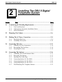
Section
2.1
IMI66–132
Installing The DSU II Digital
Telephone System
Title ........................................................................................................... Page
Considering the Mounting Requirements................................................2–4
2.1.1
2.1.2
2.1.3
Tools And Hardware ..............................................................................2–5
Underwriters Laboratories Installation Notice .......................................2–5
Hybrid Installation ..................................................................................2–5
2.2
Mounting The Cabinet...............................................................................2–6
2.3
Making The AC Power Connection .........................................................2–8
2.3.1
2.3.2
2.4
Connecting The Lines ..............................................................................2–12
2.4.1
2.4.2
2.4.3
2.5
Identifying The Fuses .............................................................................2–8
Grounding The System .........................................................................2–10
Detailing The Line Connections.......................................................... 2–14
Reassigning The Line Ports ..................................................................2–14
Protecting The Lines.............................................................................2–14
Connecting The Stations..........................................................................2–16
2.5.1
2.5.2
2.5.3
2.5.4
2.5.5
2.5.6
2.5.7
Grounding The Unused Station Cables ................................................2–17
Relocating The Stations........................................................................2–17
Installing The Cable Clips ....................................................................2–17
Connecting Stations To The J0408...................................................... 2–19
Connecting Stations To The J0816...................................................... 2–20
Connecting Stations To The J1632...................................................... 2–21
Wall Mounting The Telephone Stations...............................................2–23
Installing The DSU II Digital Telephone System 2 – 1
IMI66–132
Section
DSU II Digital Telephone System
Title ........................................................................................................... Page
2.6
Installing DSS/BLF Consoles ..................................................................2–26
2.7
Connecting A Power Failure Station......................................................2–28
2.8
Using The Auxiliary Equipment Interface ............................................2–29
2.9
Common The Audible And Auxiliary Ringing Interface .....................2–30
2.9.1
2.9.2
Connecting Outside Lines ....................................................................2–30
Connecting Selected Ports ....................................................................2–30
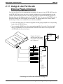
2.10 Using The External Paging Interface .....................................................2–32
2.11 Using A Line Port As An External Paging Interface............................2–33
2.12 Connecting Data Devices To The System ..............................................2–34
2.12.1
2.12.2
2.12.3
Making Modular Jack Data Connections .............................................2–34
Making The Common Equipment Data Connections.......................... 2–36
Connecting A Personal Computer For Remote Programming .............2–38
2.13 Using The Music Interface ......................................................................2–40
2.14 Using The Add-On Expansion Module ..................................................2–41
2.14.1
2.14.2
2.14.3
Using The JM408 Module ....................................................................2–41
Using The JM008 Module ................................................................... 2–44
Installing An Add-On Expansion Module........................................... 2–48
2.15 Checking The System Installation ..........................................................2–50
2.15.1
2.15.2
2.15.3
Checking The Resistance......................................................................2–50
Checking The Voltage ..........................................................................2–50
Checking The General Operating Conditions ..................................... 2–51
2 – 2 Installing The DSU II Digital Telephone System
DSU II Digital Telephone System
Section
IMI66–132
Title ........................................................................................................... Page
2.16 Isolating Failures......................................................................................2–51
2.16.1
2.16.2
Checking The System Status Indicator.................................................2–51
Testing The Stations .............................................................................2–51
2.17 Loading And Up-Grading The System Software ..................................2–52
2.17.1
2.17.2
2.17.3
Introducing The Software Key .............................................................2–52
Introducing The Software Disks...........................................................2–53
Loading The Software ..........................................................................2–54
2.18 Installing The System Options And Accessories .................................. 2–60
2.18.1
2.18.2
2.18.3
2.18.4
2.18.5
2.18.6
2.18.7
2.18.8
Installing The Battery Back Up Assembly .......................................... 2–60
Installing the Analog Terminal Interface............................................. 2–64
Installing the Data Interface Unit .........................................................2–72
Supporting Caller Identification Service ..............................................2–76
Supporting The Tracker Paging System ...............................................2–80
Supporting DVA Operation..................................................................2–82
Installing The Personal Computer Interface Unit................................. 2-84
Connecting The Versatile Voice Processing Voice Mail System ........2–86
2.19 FCC Rules And Regulations .................................................................. 2–88
Installing The DSU II Digital Telephone System 2 – 3
IMI66–132
2.1
DSU II Digital Telephone System
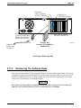
Considering The Mounting Requirements
The following requirements will help you to install the DSU II digital telephone system.
• Locate the equipment cabinet within four feet of an AC electrical outlet dedicated
exclusively to the use of this equipment. The outlet must be a 117 VAC 15 AMP circuit
with a third-wire ground supplied to a standard electrical outlet (NEMA 5–15R).
• Mount the common equipment within 25 feet of the TELCO/PBX jacks. The recommended
nominal distance is 7 feet.
• Choose a secure and dry mounting location that has adequate ventilation. The temperature
range of the location must be within 32–122 degrees F (0–50 degrees C) and that the
relative humidity is less than 90 percent, non-condensing.
• If the mounting surface is damp or if it is made of concrete or masonry material, you must
attach a backboard to the mounting surface for mounting the common equipment. Suitable
mounting backboards are available commercially or you can construct one from 3/4-inch
plywood by cutting it to size.
2 – 4 Installing The DSU II Digital Telephone System
DSU II Digital Telephone System
2.1.1
IMI66–132
Tools And Hardware
You will need the following tools and materials to install the common equipment.
• Fasteners—wood screws (1/4 x 1-inch round head), toggle bolts, or wall anchors,
• Screwdriver—to match fasteners,
• Electric drill—if prepared holes are required,
• Connecting tool—for fastening wires to a type-66 connector block,
• Crimping tool—for 623-type modular plugs,
• Volt/Ohm Meter.
2.1.2
Underwriters Laboratories Installation Notice
Per The Underwriters Laboratories standard 1459, 2nd edition, be aware of the following
precautions when installing telephone equipment that is to be directly connected to the telephone
company network:
• Never install telephone wiring during a lightning storm,
• Never install telephone jacks in wet locations unless the jack is specifically designed for
wet locations,
• Never touch un-insulated telephone wires or terminals unless the telephone line has been
disconnected at the network interface,
• Use caution when installing or modifying telephone lines.
2.1.3
Hybrid Installation
Whenever a programmer assigns lines to line groups, the digital telephone system automatically
assumes the hybrid mode. Your local telephone company may charge a higher monthly fee for
operation of a hybrid system; therefore, the FCC requires that you report the equipment-type
category designation number (KF for key system, MF for hybrid system) to the telephone
company at the time of installation.
FCC Registration Numbers
Key System
Hybrid System
CVWUSA-61535-KF-E
CVWUSA-61536-MF-E
Installing The DSU II Digital Telephone System 2 – 5
IMI66–132
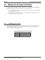
2.2
DSU II Digital Telephone System
Mounting The Cabinet
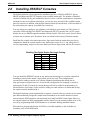
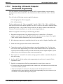
After thoroughly reviewing Section 2.1 and fully understanding its subject matter, use the
following procedure to mount the common equipment cabinet
1. Unpack and carefully inspect all equipment for shipping damage. Notify the shipper
immediately of any damages that you find. Verify that the packages contain all parts and
accessories needed for proper installation and operation.
2. If the mounting location requires a backboard, attach it securely to provide a stable mounting
surface for the equipment.
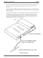
3. Refer to Figure 2-1 or to the PP032-001 mounting template included in the literature that
accompanies the common equipment cabinet for the locating dimensions required for the
three mounting screws, and mark their locations on the mounting surface.
4. Drill holes in the mounting surface of a proper size to accommodate the hardware being
used. If necessary, prepare these holes with inserts, anchors or other attachment devices as
dictated by the type of mounting surface.
5. Insert the two top screws into the mounting surface and tighten them to within approximately
1/8-inch of the surface.
6. Hang the cabinet on the top screws using the mounting holes located on the rear of the
cabinet. Note that these holes are elongated with an enlargement at one end. This feature
allows the cabinet to snap down on the screws to secure the mounting when the cabinet is
hung on them.
7. Insert a third screw through the mounting tab located on the lower edge of the cabinet and
into the mounting surface, and tighten it into place.
8. Place the individual telephone stations as desired and in keeping with accepted industry and
office standards. You can wall mount a telephone station if necessary (see Section 2.5.7 for
details).
2 – 6 Installing The DSU II Digital Telephone System
DSU II Digital Telephone System
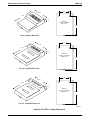
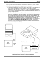
IMI66–132
0.87"
16.50"
21.30"
3.78"
Back of
4-Line, 8-Station
Base Unit
20.50"
4-Line, 8-Station Base Unit
0.88"
16.50"
27.58"
3.78"
Back of
8-Line, 16-Station
Base Unit
26.25"
8-Line, 16-Station Base Unit
0.88"
16.50"
27.58"
4.54"
Back of
16-Line, 32-Station
Base Unit
26.65"
16-Line, 32-Station Base Unit
DSU250.CDR
Detailing The DSU II Cabinet Dimensions
Installing The DSU II Digital Telephone System 2 – 7
IMI66–132
2.3
DSU II Digital Telephone System
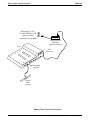
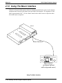
Making The AC Power Connection
You must employ a dedicated 117VAC 15 AMP circuit, with a third-wire ground, supplied to a
standard electrical outlet (NEMA 5-15R) for the AC power connection.
• For added equipment protection, connect a plug-in power line surge protector between the
power cord and the AC outlet.
• Thoroughly check out the installation before connecting the power cord to an electrical
outlet to apply AC power to the system.
2.3.1
Identifying The Fuses
The system is protected against short circuit damage by a fuse located on the right side of the
common equipment cabinet. Always replace the fuse with one of the same value and type;
otherwise, equipment damage could result.
Comparing Cabinets And Their Fuse Types
Cabinet
J0408
J0816
J1632
Fuse Value
1A 250V slow-blow type
3A 250V slow-blow type
3A 250V slow-blow type
2 – 8 Installing The DSU II Digital Telephone System
DSU II Digital Telephone System
IMI66–132
Dedicated 117VAC
15 AMP NEMA 5-15R
electrical outlet
with third-wire ground
Plug-in power
line surge
protector (typical)
DSU211
Fuse
(See text)
Grounding
terminal
Typical
earth
ground
Making The AC Power Connections
Installing The DSU II Digital Telephone System 2 – 9
IMI66–132
2.3.2
DSU II Digital Telephone System
Grounding The System
If spare conductors exist in the cables between the station and the 66M-xx connector blocks, it is
good practice to connect them to an earth ground. Doing this may help prevent them from
inducing radio frequency and/or AC interference into the system. It is also good practice to
disconnect any unused station jacks from the connector block and ground that wiring to an earth
ground as well.
Transient voltage spikes, if induced onto CO or CENTREX lines, can travel through the cable
and into the common equipment. The telephone company offers basic protection against this
condition but it is usually designed to protect the central office circuits. While it will also
provide some protection to the common equipment, you should not rely upon it for total
protection. To help ensure that external over-voltage surges do not damage the system, you
should install and properly ground primary protection devices, such as gas discharge tubes or
similar devices, on all lines. While the line boards have internal secondary surge protection on
all line ports, in order for this protection to be effective, you MUST connect the common
equipment cabinet to a reliable, effective earth ground.
Proper DSU grounding is necessary for trouble-free operation and personnel safety. The DSU
has the following three types of grounds:
• Service Ground—a neutral power line wire that is connected to the ground bus in the
premises’ AC power panel,
• System Ground—a non-current carrying power line wire that is connected to the ground bus
in the premises’ AC power panel,
• Frame Ground—a low impedance conductor that places the common equipment cabinet at
reference ground potential. The frame ground provides the greatest safety by limiting
electrical potential between non-current carrying parts of the system. The common
equipment cabinet provides a ground stud on its cabinet for access to its frame ground.
Effective grounding requires that you connect the frame ground to a good earth ground. A good
earth ground is one such as the ground bus in the premises’ AC power panel or a public metallic
cold water pipe at a point immediately at its entrance to the premises and ahead of any meters,
pumps, or insulating sections that have been added for vibration reduction. Avoid using the
premises’ structural steel frame as it may not be at earth ground potential. Make the ground
connection with #10 or #12 insulated, solid copper grounding wire. Keep the ground wire
separate from the three-wire AC line cord ground, do not splice it, and keep it as short as
possible.
The impedance of the wiring between the common equipment cabinet and the earth ground must
not exceed 0.25 ohms and the impedance between the earth ground and the power company’s
reference standard ground must not exceed 4 ohms. Use an acceptable low impedance measuring
device to measure the impedance of these paths. The #10 or #12 wire size will minimize the
wiring impedance; however, if the impedance between earth ground and the power company’s
standard reference ground exceeds 5 ohms, contact the local power company. The ground path
must always be of sufficient current-carrying capacity to prevent a build up of voltages that may
result in circuit noise, hazard to personnel, or equipment damage.
2 – 10 Installing The DSU II Digital Telephone System
DSU II Digital Telephone System
IMI66–132
Be sure that all of the ground connections are without splices and are visible for inspection and
maintenance. Tag all of the ground connections with a sign that reads: Do Not Remove Or
Disconnect.
If you install expansion modules on the base cabinet, attach at least a #10 or #12 insulated, solid
copper wire between the frame ground stud on the expansion module(s) to the frame ground stud
on the base cabinet.
Remember, if spare conductors exist in the cables that run between the stations and the 66M-xx
connector blocks, it is good practice to connect them to earth ground. Doing this may help
prevent them from introducing radio frequency and/or AC interference into the system. Also
remember that it is good practice to disconnect any unused station jacks from the connector
block and ground that wiring to earth ground as well.
DSU212
Frame Ground Stud
#10 or #12 Insulated, Solid
Copper Grounding Wire
Typical Earth Ground (see text)
Grounding The System
Installing The DSU II Digital Telephone System 2 – 11
IMI66–132
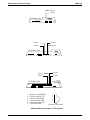
2.4
DSU II Digital Telephone System
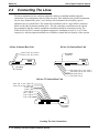
Connecting The Lines
The line terminations for the common equipment cabinet are standard modular plug/jack
connections. Line configuration must be loop start only. Each modular jack provides termination
for two lines. Modular line jacks 1 and 2 also provide termination for an auxiliary pair in
addition to the two outside lines. The outside line termination can be a type 66M-xx connector
block or individual 6-position modular jacks. The line cord that is routed between the outside
line termination and the common equipment termination should be twisted-pair wiring. The
J0408, J0816 and J1632 common equipment supports the installation of up to 4, 8, or 16 lines,
respectively. Add-on expansion modules are available to expand the line capacity of the systems.
8-Line, 16-Station Base Unit
4-Line, 8-Station Base Unit
Lines 3 & 4, Aux. Line 4
Lines 1 & 2, Aux. Line 2
Grounding
Terminal
Grounding
Terminal
Line Jacks 1 & 2, Aux. Line 2
Line Jacks 3 & 4, Aux. Line 4
Line Jacks 5 & 6
Line Jacks 7 & 8
16-Line, 32-Station Base Unit
Lines 1 & 2, Aux 1 (Line 2)
Lines 3 & 4, Aux 2 (Line 4)
Lines 5 & 6
Lines 7 & 8
Line 9 & 10
Line 11 & 12
Line 13 & 14
Line 15 & 16
DSU219
Grounding
Terminal
Locating The Line Connections
2 – 12 Installing The DSU II Digital Telephone System
DSU II Digital Telephone System
IMI66–132
(Typical 8-Line, 16-Station
Base Unit Shown)
6-Wire Twisted
Pair Cable
{
{
{
{
RING 2
RING 1
TIP 1
TIP 2
RING 4
RING 3
TIP 3
TIP 4
CO/PBX
LINES
RING 6
RING 5
TIP 5
TIP 6
RING 8
RING 7
TIP 7
TIP 8
Line Terminations
Type 66M-XX
Connector Block
or
Individual 6-Position
Modular jacks
Aux. Ring
6
Ring 2
5
Ring 1
4
3
Tip 1
2
Tip 2
1
Aux. Tip
Pin designation for
Line Jacks 1 and 2
No Conn.
Ring 2
6
5
Ring 1
4
3
Tip 1
2
Tip 2
1
No. Conn.
Pin designation for
Line Jacks 5 and 6
CAJS083
Detailing The CO Interface
Installing The DSU II Digital Telephone System 2 – 13
IMI66–132
2.4.1
DSU II Digital Telephone System
Detailing The Line Connections
The table on the next page shows the line connection details for all three of the common
equipment base units. Jacks one and two are the same for all three cabinets, jacks three and four
are the same for both the J0816 and J1632 cabinets, and jacks five through eight are only
available on the J1632 cabinet.
2.4.2
Reassigning The Line Ports
After you have initially connected a line to a particular line port and programmed its attributes
(or left it with the system defaulted values), you can reassign the line and its attributes to a
different port by programming action if you wish. Refer to Chapter 3 for the line to line port
reassignment programming details.
CAUTION
While this feature allows you to make adds, moves, and changes without relocating the line
wiring, it is not a substitute for correct wiring and should not be used as such. Be sure to
record any reassignments that you make.
2.4.3
Protecting The Lines
Transient voltage spikes, if induced onto CO or CENTREX lines, can travel through the cable
and into the common equipment. The telephone company offers basic protection against this
condition but it is usually designed to protect the central office circuits. While it will also
provide some protection to the common equipment, it should not be relied upon for total
protection. To help ensure that external over-voltage surges do not damage the system, the
manufacturer recommends that gas discharge tubes, or similar primary protection devices, be
installed and properly grounded on all lines (a selection of solid-state protection devices that are
useful for this purpose is available from ITW Linx, Elk Grove Village, Illinois 60007).
2 – 14 Installing The DSU II Digital Telephone System
DSU II Digital Telephone System
IMI66–132
Understanding The Line Connection Details
Common Equipment Type
J0408,
J0816,
and
J1632
Line Jack
1
2
3
J0816
and
J1632
4
5
6
J1632
7
8
Pin No.
1
2
3
4
5
6
1
2
3
4
5
6
1
2
3
4
5
6
1
2
3
4
5
6
1
2
3
4
5
6
1
2
3
4
5
6
1
2
3
4
5
6
1
2
3
4
5
6
Connection
Auxiliary 1 (Line 2) Tip
Line 2 Tip
Line 1 Tip
Line 1 Ring
Line 2 Ring
Auxiliary 1 (Line 2) Ring
Auxiliary 2 (Line 4) Tip
Line 4 Tip
Line 3 Tip
Line 3 Ring
Line 4 Ring
Auxiliary 2 (Line 4) Ring
No Connection
Line 6 Tip
Line 5 Tip
Line 5 Ring
Line 6 Ring
No Connection
No Connection
Line 8 Tip
Line 7 Tip
Line 7 Ring
Line 8 Ring
No Connection
No Connection
Line 10 Tip
Line 9 Tip
Line 9 Ring
Line 10 Ring
No Connection
No Connection
Line 12 Tip
Line 11 Tip
Line 11 Ring
Line 12 Ring
No Connection
No Connection
Line 14 Tip
Line 13 Tip
Line 13 Ring
Line 14 Ring
No Connection
No Connection
Line 16 Tip
Line 15 Tip
Line 15 Ring
Line 16 Ring
No Connection
Telephone Number
Installing The DSU II Digital Telephone System 2 – 15
IMI66–132
2.5
DSU II Digital Telephone System
Connecting The Stations
The DSU II digital telephone system supports the operation of proprietary Comdial telephones.
The J0408, J0816 and J1632 common equipment supports the installation of up to eight, 16, or
32 telephones, respectively. Add-on expansion modules are available to expand the station
capacity of the systems. You can add one expansion module to the J0408, and two expansion
modules to the J0816 and J1632. The JM408 expansion module provides interface for eight
proprietary stations (plus interface for four lines) while the JM008 expansion module provides
interface for eight industry-standard devices.
Connections between the common equipment and the stations are typically via type 66M-xx
connector blocks which are cable connected to the common equipment’s 50–pin male connector.
The connector block is, in turn, wired to modular jacks that accept the modular line cord
connected between it and the telephones.
The maximum distance allowed from the common equipment to the stations is per the following
list:
• Multiline Telephones—1000 feet using #24 gauge, twisted-pair cable or 2000 feet using
#22 gauge cable
When installing the system telephones keep in mind that each station port supports only one
proprietary telephone and the system does not allow you to bridge two stations to a single
modular jack.
Always route station wiring a minimum of 12 inches from any other parallel wires or electrical
devices. If electrical noise or RF energy is at a high level, you may need to use shielded cable
with the shield connected to the cabinet ground lug.
2 – 16 Installing The DSU II Digital Telephone System
DSU II Digital Telephone System
2.5.1
IMI66–132
Grounding The Unused Station Cables
Remember, if spare conductors exist in the cables that run between the stations and the 66M-xx
connector blocks, it is good practice to connect them to earth ground. Doing this may help
prevent them from introducing radio frequency and/or AC interference into the system. Also
remember that it is good practice to disconnect any unused station jacks from the connector
block and ground that wiring to earth ground as well.
Remove insulation and twist together all spare wires at the wall outlet. Ground the wires at the
66M-xx to the common equipment cabinet ground lug.
2.5.2
Relocating The Stations
The Comdial proprietary telephones identify themselves to the system when you install them.
The system assigns an extension number and all other programmable attributes to station ports as
a default that you can reprogram as needed. Plus, you can use programming action to reassign
attributes of one station port to a different station port if you wish. Refer to the automatic station
relocation programming procedure and the station-to-station programming procedure found in
Chapter 3.
NOTE: The system will not allow you to relocate the station 10 to station port 10 assignment.
CAUTION
While this feature allows you to make adds, moves, and changes without relocating the station
wiring, it is not a substitute for correct wiring and should not be used as such. Be sure to
record any reassignments that you make.
2.5.3
Installing The Cable Clips
Each cabinet-mounted 50-pin male connector is equipped with a retaining clip. This clip is
designed to secure the mated connection once it is made. The clip does this by snapping into a
slot on the cable-mounted connector when it is pressed together with the cabinet-mounted
connector. This retaining clip must be pulled back slightly to unsnap it before the connectors can
be separated.
Installing The DSU II Digital Telephone System 2 – 17
IMI66–132
DSU II Digital Telephone System
8-Line, 16-Station Base Unit
4-Line, 8-Station Base Unit
Station 10-17,
Power Fail Station
Grounding
Terminal
Grounding
Terminal
Station 10-25
Power Fail Station
16-Line, 32-Station Base Unit
Stations 10-25
Power Fail Station
(pins 3 & 4)
Stations 26-41
DSU220
Grounding
Terminal
Locating The Station Connections
2 – 18 Installing The DSU II Digital Telephone System
DSU II Digital Telephone System
2.5.4
IMI66–132
Connecting Stations To The J0408
This table shows the color-coded connections for a J0408 common equipment cabinet.
Connecting Stations To The J0408 Common Equipment Cabinet
25-Pair Connections
Wire Color
White-Blue
Blue-White
White-Orange
Orange-White
White-Green
Green-White
White-Brown
Brown-White
White-Slate
Slate-White
Red-Blue
Blue-Red
Red-Orange
Orange-Red
Red-Green
Green-Red
Red-Brown
Brown-Red
Red-Slate
Slate-Red
Black-Blue
Blue-Black
Black-Orange
Orange-Black
Black-Green
Green-Black
Black-Brown
Brown-Black
Black-Slate
Slate-Black
Yellow-Blue
Blue-Yellow
Yellow-Orange
Orange-Yellow
Yellow-Green
Green-Yellow
Yellow-Brown
Brown-Yellow
Yellow-Slate
Slate-Yellow
Violet-Blue
Blue-Violet
Violet-Orange
Orange-Violet
Violet-Green
Green-Violet
Violet-Brown
Brown-Violet
Violet-Slate
Slate-Violet
Clip
Pair Pin No.
Term.
26
1
1
1
2
27
3
2
2
4
28
5
3
3
6
29
7
4
4
8
30
9
5
5
10
31
11
6
6
12
32
13
7
7
14
33
15
8
8
16
34
17
9
9
18
35
19
10
10
20
36
21
11
11
22
37
23
12
12
24
38
25
13
13
26
39
27
14
14
28
40
29
15
15
30
41
31
16
16
32
42
33
17
17
34
43
35
18
18
36
44
37
19
19
38
45
39
20
20
40
46
41
21
21
42
47
43
22
22
44
48
45
23
23
46
49
47
24
24
48
50
49
25
25
50
Two-Wire Connections
Pair
Signal Path
Signal Path
Signal Path
Signal Path
Signal Path
Signal Path
Signal Path
Signal Path
Wire Color
Green
Red
Green
Red
Green
Red
Green
Red
Green
Red
Green
Red
Green
Red
Green
Red
Station Connections
Station
Location
10
11
12
13
14
15
16
17
Common Audible
Station 17 Audible
Power Fail Station
Installing The DSU II Digital Telephone System 2 – 19
IMI66–132
2.5.5
DSU II Digital Telephone System
Connecting Stations To The J0816
This table shows the color-coded connections for a J0816 common equipment cabinet.
Connecting Stations To The J0816 Common Equipment Cabinet
25-Pair Connections
Wire Color
White-Blue
Blue-White
White-Orange
Orange-White
White-Green
Green-White
White-Brown
Brown-White
White-Slate
Slate-White
Red-Blue
Blue-Red
Red-Orange
Orange-Red
Red-Green
Green-Red
Red-Brown
Brown-Red
Red-Slate
Slate-Red
Black-Blue
Blue-Black
Black-Orange
Orange-Black
Black-Green
Green-Black
Black-Brown
Brown-Black
Black-Slate
Slate-Black
Yellow-Blue
Blue-Yellow
Yellow-Orange
Orange-Yellow
Yellow-Green
Green-Yellow
Yellow-Brown
Brown-Yellow
Yellow-Slate
Slate-Yellow
Violet-Blue
Blue-Violet
Violet-Orange
Orange-Violet
Violet-Green
Green-Violet
Violet-Brown
Brown-Violet
Violet-Slate
Slate-Violet
Pair
1
2
3
4
5
6
7
8
9
10
11
12
13
14
15
16
17
18
19
20
21
22
23
24
25
Pin
No.
26
1
27
2
28
3
29
4
30
5
31
6
32
7
33
8
34
9
35
10
36
11
37
12
38
13
39
14
40
15
41
16
42
17
43
18
44
19
45
20
46
21
47
22
48
23
49
24
50
25
Two-Wire Connections
Clip
Term.
1
2
3
4
5
6
7
8
9
10
11
12
13
14
15
16
17
18
19
20
21
22
23
24
25
26
27
28
29
30
31
32
33
34
35
36
37
38
39
40
41
42
43
44
45
46
47
48
49
50
Pair
Signal Path
Signal Path
Signal Path
Signal Path
Signal Path
Signal Path
Signal Path
Signal Path
Signal Path
Signal Path
Signal Path
Signal Path
Signal Path
Signal Path
Signal Path
Signal Path
2 – 20 Installing The DSU II Digital Telephone System
Wire Color
Green
Red
Green
Red
Green
Red
Green
Red
Green
Red
Green
Red
Green
Red
Green
Red
Green
Red
Green
Red
Green
Red
Green
Red
Green
Red
Green
Red
Green
Red
Green
Red
Station Connections
Station
Location
10
11
12
13
14
15
16
17
18
19
20
21
22
23
24
25
Common Audible
Station 17 Audible
Power Fail Station
DSU II Digital Telephone System
2.5.6
IMI66–132
Connecting Stations To The J1632
The following two tables show the color-coded connections for a J1632 common equipment
cabinet.
Connecting Stations To J1 On The J1632 Common Equipment Cabinet
25-Pair Connections
Wire Color
White-Blue
Blue-White
White-Orange
Orange-White
White-Green
Green-White
White-Brown
Brown-White
White-Slate
Slate-White
Red-Blue
Blue-Red
Red-Orange
Orange-Red
Red-Green
Green-Red
Red-Brown
Brown-Red
Red-Slate
Slate-Red
Black-Blue
Blue-Black
Black-Orange
Orange-Black
Black-Green
Green-Black
Black-Brown
Brown-Black
Black-Slate
Slate-Black
Yellow-Blue
Blue-Yellow
Yellow-Orange
Orange-Yellow
Yellow-Green
Green-Yellow
Yellow-Brown
Brown-Yellow
Yellow-Slate
Slate-Yellow
Violet-Blue
Blue-Violet
Violet-Orange
Orange-Violet
Violet-Green
Green-Violet
Violet-Brown
Brown-Violet
Violet-Slate
Slate-Violet
Pair
1
2
3
4
5
6
7
8
9
10
11
12
13
14
15
16
17
18
19
20
21
22
23
24
25
Pin
No.
26
1
27
2
28
3
29
4
30
5
31
6
32
7
33
8
34
9
35
10
36
11
37
12
38
13
39
14
40
15
41
16
42
17
43
18
44
19
45
20
46
21
47
22
48
23
49
24
50
25
Two-Wire Connections
Clip
Term.
1
2
3
4
5
6
7
8
9
10
11
12
13
14
15
16
17
18
19
20
21
22
23
24
25
26
27
28
29
30
31
32
33
34
35
36
37
38
39
40
41
42
43
44
45
46
47
48
49
50
Pair
Signal Path
Signal Path
Signal Path
Signal Path
Signal Path
Signal Path
Signal Path
Signal Path
Signal Path
Signal Path
Signal Path
Signal Path
Signal Path
Signal Path
Signal Path
Signal Path
Wire Color
Green
Red
Green
Red
Green
Red
Green
Red
Green
Red
Green
Red
Green
Red
Green
Red
Green
Red
Green
Red
Green
Red
Green
Red
Green
Red
Green
Red
Green
Red
Green
Red
Station Connections
Station
Location
10
11
12
13
14
15
16
17
18
19
20
21
22
23
24
25
Installing The DSU II Digital Telephone System 2 – 21
IMI66–132
DSU II Digital Telephone System
Connecting Stations To J2 On The J1632 Common Equipment Cabinet
25-Pair Connections
Wire Color
White-Blue
Blue-White
White-Orange
Orange-White
White-Green
Green-White
White-Brown
Brown-White
White-Slate
Slate-White
Red-Blue
Blue-Red
Red-Orange
Orange-Red
Red-Green
Green-Red
Red-Brown
Brown-Red
Red-Slate
Slate-Red
Black-Blue
Blue-Black
Black-Orange
Orange-Black
Black-Green
Green-Black
Black-Brown
Brown-Black
Black-Slate
Slate-Black
Yellow-Blue
Blue-Yellow
Yellow-Orange
Orange-Yellow
Yellow-Green
Green-Yellow
Yellow-Brown
Brown-Yellow
Yellow-Slate
Slate-Yellow
Violet-Blue
Blue-Violet
Violet-Orange
Orange-Violet
Violet-Green
Green-Violet
Violet-Brown
Brown-Violet
Violet-Slate
Slate-Violet
Pair
1
2
3
4
5
6
7
8
9
10
11
12
13
14
15
16
17
18
19
20
21
22
23
24
25
Pin
No.
26
1
27
2
28
3
29
4
30
5
31
6
32
7
33
8
34
9
35
10
36
11
37
12
38
13
39
14
40
15
41
16
42
17
43
18
44
19
45
20
46
21
47
22
48
23
49
24
50
25
Two-Wire Connections
Clip
Term.
1
2
3
4
5
6
7
8
9
10
11
12
13
14
15
16
17
18
19
20
21
22
23
24
25
26
27
28
29
30
31
32
33
34
35
36
37
38
39
40
41
42
43
44
45
46
47
48
49
50
Pair
Signal Path
Signal Path
Signal Path
Signal Path
Signal Path
Signal Path
Signal Path
Signal Path
Signal Path
Signal Path
Signal Path
Signal Path
Signal Path
Signal Path
Signal Path
Signal Path
2 – 22 Installing The DSU II Digital Telephone System
Wire Color
Green
Red
Green
Red
Green
Red
Green
Red
Green
Red
Green
Red
Green
Red
Green
Red
Green
Red
Green
Red
Green
Red
Green
Red
Green
Red
Green
Red
Green
Red
Green
Red
Station Connections
Station
26
27
28
29
30
31
32
33
34
35
36
37
38
39
40
41
Location
DSU II Digital Telephone System
2.5.7
IMI66–132
Wall Mounting The Telephone Stations
The DigiTech (product code 77nnn), Impact (product code 8nnnn), and Impression (product
code 2nnnn) telephones are shipped from the factory configured for desk use. To convert them
for wall-mounting, follow the procedures outlined below.
To convert the DigiTech model 77nnn telephones for wall-mounting,
1. Disconnect line cord and handset cord from telephone.
2. Turn telephone over to expose lower housing.
CAUTION
The telephone circuitry is sensitive to static electricity discharge. Be sure that your body and
the workplace are properly grounded to avoid any static electricity discharge while you
perform step 3.
3. Remove screws that attach lower housing to
upper housing. Carefully separate lower and
upper housings making sure not to disconnect
wiring between them.
Remove lo er ho sin ,
rotate 1 de rees
and replace
4. Rotate lower housing 180 degrees. Do not
disturb any internal wiring.
5. Refasten lower housing to upper housing.
Make sure no wires are caught between upper
and lower housings. Do not over-tighten
screws wile refastening the housings.
CAHS
6. Route line cord through appropriate channel
on lower housing, and reconnect it to
telephone. You may substitute a shorter line
cord if you wish.
3
Upper ho sin
7. Reconnect the handset cord.
Rotating The Lower Housing On
Model 77nnn Telephones
Installing The DSU II Digital Telephone System 2 – 23
IMI66–132
DSU II Digital Telephone System
To convert the Impact (models 80nnn and 81nnn) and Impression (models 20nn
and 21nnn) telephones for wall-mounting,
1. Turn telephone over and disconnect line cord and handset cord from telephone. Do not
damage line cord on plastic dressing tabs.
2. Remove screws from pedestal and unlatch it from telephone housing, rotate it 180 degrees,
re-latch its tabs in the slots in the lower housing of the telephone, and replace screws.
3. Route line cord as appropriate, and reconnect it to telephone. Substitute shorter line cord if
desired.
4. This telephone has a reversible handset retaining hook. When wall mounting, pull up this
hook and rotate it 180 degrees.
5. Reconnect the handset cord.
There are wall-mounting enhancement kits available through your normal distribution channels.
These kits include a handset cradle cup that you can screw-mount to the telephone’s upper
housing. The product codes for these enhancement kits are: HCCI for the Impact telephones
(models 80nnn and 81nnn) and Impression telephones (models 20nnn and 21nnn), and HCCX
for the DigiTech telephones (model 77nnn).
Rotate pedestal
1 de r
ees for
a
ll mo n
tin .
Pedestal
Lo e
r
Ho s
in
Unsnap
Pedestal
Here
CAJS
5
P l
psprin loaded
handset
a
ll tab,
rotate it 1 de r
ees,
and release.
CAJS
4
Reversing The Pedestal And Handset Hook
(Model 80nnn, 81nnn, 20nnn and 21nnn Telephones)
2 – 24 Installing The DSU II Digital Telephone System
DSU II Digital Telephone System
IMI66–132
To wall-mount the telephones,
After configuring a telephone for wall mounting, either mount it directly on the wall using two
#10 pan-head screws (obtained locally), or mount it on a wall jack cover plate. If using a wall
jack cover plate, use an AT&T type 630B wall plate for best results.
1. If #10 screws are used, thread them into the wall within 1/8-inch of the surface. Refer to the
illustration for the spacing dimensions.
2. Position the keyhole-shaped holes in the bottom of the telephone over the #10 screws or the
cover plate studs. Slide the telephone down until a slight click is felt.
3. To remove the telephone, lift to unsnap both screws or studs from the bottom housing, and
then lift away from the wall.
Wall Plate - OR - #10 Screws
NOTE: AT&T 630B wall plate is recommended
for secure mount.
3 15/16"
CAJS006
Detailing The Station Wall Mounting
Installing The DSU II Digital Telephone System 2 – 25
IMI66–132
2.6
DSU II Digital Telephone System
Installing DSS/BLF Consoles
The digital telephone system supports the installation and use of DigiTech DD32X, Impact
IB64X, and Impression DU32X consoles at any available station port. The number of installed
consoles is limited only by port availability; however, since a console complements a companion
telephone located in an adjacent station port, you can use up to one-half of the available station
ports for consoles. In addition, with the dual console feature (discussed later), a full two-thirds of
the total station port capacity is available for console use.
You can assign two consoles to one telephone, each taking its own station port. This feature is
especially useful with DigiTech DD32X and Impression DU32X consoles and a J1632 system
that has one or two JM408 expansion modules included with it. This dual console feature allows
a station user to monitor up to 48 stations from one station location using 32-button consoles.
Install the first console at the station port that is logic-paired with the station that you wish to
complement. Install the second console at any station port except 10 or 11 and, using class of
service programming, assign it to the same station port that is logic-paired with the first console.
Detailing The Digital Station Port Logic Pairing
10–11
12–13
14–15
16–17
18–19
20–21
22–23
24–25
26–27
28–29
30–31
32–33
34–35
36–37
38–39
40–41
42–43
44–45
46–47
48–49
50–51
52–53
54–55
56–57
You can install the DSS/BLF console at any station port and assign it to a station without first
installing a console at the station’s logic-paired port if you wish. This configuration is
convenient for adding a console to an existing telephone installation that already has its
logic-paired port occupied; however, do not use this configuration for assigning a console to
station ports 10 and 12 because the console buttons will not be usable for programming. As
discussed above, this feature is also useful for adding a second console to a station that already
has a paired console installed with it.
The digital telephone system automatically recognizes a console when you connect it to a station
port and automatically assigns the station intercom numbers to the console buttons for direct
station selection (DSS) purposes with associated busy lamp field (BLF) status lights. However,
the console buttons are fully programmable and the station user can customize them as he or she
sees fit by programming them as DSS buttons or as automatic dialing (autodial) buttons.
When the user programs the buttons for DSS use, autodial capability is also available at a
secondary level at each DSS button.
2 – 26 Installing The DSU II Digital Telephone System
DSU II Digital Telephone System
IMI66–132
While the first console (the one installed at the logic-paired port) extends the autodial buttons of
the paired telephone by 48 and provides DSS/BLF coverage for station ports 10 through 57, the
second console (the one installed at the programmed station port) provides DSS/BLF coverage
as follows:
• On a 32-station system with two 8-station expansion modules, the first 16 buttons are
automatically assigned (defaulted) to station ports 42 through 57 for DSS purposes.
• On a 32-station system with one 8-station expansion module, the first 8 buttons are
automatically assigned (defaulted) to station ports 42 through 49 for DSS purposes.
• On any other smaller station capacity system, all buttons are unassigned.
When you install a console and program it to complement a telephone without first having a
console installed at a port that is logic-paired to that telephone, its button assignment is
automatically defaulted, as described above, but the user can reprogram it as required. It is
important to remember that when you program for a second console, the system sets the console
button mapping to that which is described above. When you clear the assignment, the system
resets the button mapping to match a logic-paired console. This means that when you clear the
second console feature, the console installed at that port complements the telephone that is
installed at its logic-paired port instead of the telephone that is located at the program-designated
port, and its buttons are automatically reassigned to station ports 10 through 57.
{
{
{
DIGITECH
COMDIAL
1
2
3
4
5
6
7
8
9
10
11
12
13
14
15
16
17
18
19
20
21
22
23
24
25
26
27
28
29
30
31
32
33
34
35
36
37
38
39
40
41
42
43
44
45
46
47
48
49
50
50
26
25
1
CLIP TERMIINALS
TRANS
CONF
TAP
SPKR
MUTE
HOLD
Typical
Telephone
CAJS008
ITCM
Paired-Port
DSS/BLF
Console
Second
DSS/BLF
Console
Connecting DSS/BLF Consoles
Installing The DSU II Digital Telephone System 2 – 27
IMI66–132
2.7
DSU II Digital Telephone System
Connecting A Power Failure Station
The system provides a tip and ring pair connected to line 1 as an emergency power failure
circuit. This circuit is active during a commercial AC power failure if an external battery
assembly is not installed to provide battery back-up power to the system. Connect an industry
standard, single-line telephone, such as a model 2500, to a power failure pair and use it to
provide communications capability until the AC power to the system is restored.
NOTE: The system also provides one power failure connection with each add-on expansion
module.
Power Failure Terminals on
Station Connection Block
(4-Line, 8-Station and 8-Line, 16-Station Base Units)
Typical Industry Standard
Non-electronic Telephone
(Power Failure Interface)
{
37
38
39
40
41
42
43
44
45
46
47
48
49
50
123456
Power Failure Jack (pins 3 & 4)
(16-Line, 32-Station Base Unit)
DSU221
Pin 3 = Power Failure Tip
Pin 4 = Power Failure Ring
Typical Industry Standard
Non-electronic Telephone
(Power Failure Interface)
Making A Power Failure Connection
2 – 28 Installing The DSU II Digital Telephone System
DSU II Digital Telephone System
2.8
IMI66–132
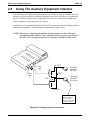
Using The Auxiliary Equipment Interface
You can connect an industry-standard telephone or a data device such as a modem or a FAX
machine on a line ahead of the common equipment if you wish. If you do so, the system can
detect an off-hook condition in the connected device and turn on the line status light at the
system telephones to indicate that the line is busy.
Connection is across tip and ring of lines 2 and 4. The system provides the auxiliary interface
connections at terminals 1 and 6 of common equipment line jacks 1 and 2.
NOTE: When you are employing this auxiliary interface feature, the line-to-line port
reassignment feature (Section 2.4.2 ) works as described except in regard to line 2
and line 4. You can only reassign Line 2 to line port 4 and line 4 to line port 2.
Line
Jack
1
Line
Jack
2
TIP 2
{
{
1
2
3
4
5
6
Auxiliary
Interface
for Line 2
RING 2
Auxiliary
Interface
for Line 4
TIP 4
1
2
3
4
5
6
RING 4
Optional non-key
system telephone
device or data
device. (No A-lead
control required)
DSU210
Making The Auxiliary Interface Connections
Installing The DSU II Digital Telephone System 2 – 29
IMI66–132
2.9
DSU II Digital Telephone System
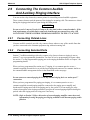
Connecting The Common Audible
And Auxiliary Ringing Interface
You can use the relay closure dry-contact points for controlling external audible equipment.
These contact closures track the pattern of the ringing for incoming calls. The contacts are closed
during the ringing period and are open during the silent period.
CAUTION
Do not exceed a 1 amp at 24 volts (0.5 amp at 48 volts) load on these control terminals. If the
load requirements exceed this limit, connect the load through an external slave relay. DO
NOT CONNECT THESE CONTROL TERMINALS DIRECTLY TO THE 117VAC LINE.
2.9.1
Connecting Outside Lines
Common audible terminals provide a dry-contact closure whenever any of the outside lines that
you have connected to the common equipment ring with an incoming call.
2.9.2
Connecting Selected Ports
Station 17 audible terminals provide a dry-contact relay closure whenever ringing is sent to
station 17 or to a programmable destination. Use class of service programming to choose either
the station 17 or the programmable paging port as the ringing destination. Refer to Chapter 3 for
programming details.
When you have programmed for station port 17 ringing, it is a common practice to use a
customer-supplied external device to provide loud ringing and connected in a manner similar to
the common audible arrangement shown in the illustration on the next page.
CAUTION
Do not connect an external paging device or any external ringing device to station port 17
connections.
When you have programmed for paging port ringing, it is a common practice to use a
customer-supplied external paging amplifier connected to the paging port to amplify and
broadcast the ringing tones sent to the paging port by the system. You can employ the relay
closures that appear at the ringing terminals to energize the external paging amplifier during the
periods when the ringing tones are being sent if necessary.
NOTE: Refer to Section 2.10 for a discussion of external paging amplifier connections and
information for using the paging port ringing terminals in an alternate paging enable
function.
2 – 30 Installing The DSU II Digital Telephone System
DSU II Digital Telephone System
IMI66–132
(Wiring shown for low current application - see caution text)
Signalling
Device
Wire to
Common
Audible
Interface
Relay
Power
Source for
Signalling
Device
24V @ 1A Max.
48V @ .5A Max.
AC or DC
Input as
Required
(Wiring shown with slave relay connection for high current application - see caution text)
Wire to
Common
Audible
Interface
Relay
24V @ 1A Max.
48V @ .5A Max.
Power
Source for
Slave
Relay
AC or DC
Input as
Required
Power
Source for
Signalling
Device
AC or DC
Input as
Required
Voltage Clamping Device
Recommended
Signalling
Device
Slave
Relay
Common
Audible {
{
Station 17
Audible
39
40
41
42
43
44
45
46
47
48
49
50
123456
26
Common Audible Jack (pins 1 & 6)
(16-Line, 32-Station Base Unit)
1
CLIP TERMIINALS
Station Connector Block
(4-Line, 8-Station and
8-Line, 16-Station Base Units)
Pin 1
Pin 6
}=Common Audible Pair
DSU222
Connecting Typical Common Audible Interface Wiring
Installing The DSU II Digital Telephone System 2 – 31
IMI66–132
DSU II Digital Telephone System
2.10 Using The External Paging Interface
The system provides a special transformer-isolated paging port that you can use to couple the
system to a customer-supplied external paging amplifier. This external paging port does not
provide a talk-back path nor will it recognize DTMF dial tones.
You can use the relay closure dry-contact points that the system makes available at the ringing
port terminal for controlling the external paging amplifier during a paging operation. These
contacts close and stay closed during the time that a paging operation is active to provide a
constant enable signal path for the paging amplifier.
NOTE: This paging enable constant closure function overrides the ring pattern closure
provided when ringing is sent to the paging port.
• Connect the audio input of a customer-supplied external paging amplifier to the paging port.
• If the paging amplifier requires an enable signal, connect the enable leads to the station 17
audible terminals.
Paging Port
J0408 Base Unit
Paging Port
J1 Connector Block
Station 17 Audible Connection for
(J0408 and J0816 Systems)
J0816 Base Unit
Connect Audio
Input To Common
Equipment
Paging Port
123456
PA System
Audio Input
Enable Input
Paging Port
DSU224
Pin 2
Pin 5
}=Station 17 Audible Pair
J1632 Base Unit
1
2
3
4
5
6
7
8
9
10
11
12
13
14
15
16
17
18
19
20
21
22
23
24
25
26
27
28
29
30
31
32
33
34
35
36
37
38
39
40
41
42
43
44
45
46
47
48
49
50
50
26
25
1
CLIP TERMIINALS
DSU224
Connecting A Typical External Paging Interface
2 – 32 Installing The DSU II Digital Telephone System
DSU II Digital Telephone System
IMI66–132
2.11 Using A Line Port As An
External Paging Interface
You can use class of service programming to program a line port to be an AUXILIARY port. As
an AUXILIARY port, a user can use it to couple a telephone to an external paging device that
you have wired to the line port. He or she does this from any station with that line presence by
pressing the proper line button to select the AUXILIARY port. The user can dial DTMF tones or
dial pulses through the AUXILIARY port as needed. The paging enable relay closure feature
discussed previously is not available for use with this installation.
• Connect the audio input of a customer-supplied external paging amplifier to the tip and ring
leads of the AUXILIARY port.
• You can install a DTMF tone select, zone-paging amplifier if you wish. If you do install
this type of amplifier, the user must dial the zone-select code after he or she presses the
AUXILIARY port line select button.
PA System
Audio
Input
Program line port as
auxiliary port and connect
PA system to tip and ring
pair of that port.
{
{
{
{
RING 2
RING 1
TIP 1
TIP 2
RING 4
RING 3
TIP 3
TIP 4
RING 6
RING 5
TIP 5
TIP 6
RING 8
RING 7
TIP 7
TIP 8
CO/PBX
LINES
Line Termination
Type 66M-XX
Connector Block
or
Individual 6-Position
Modular Jacks
.
.
DSU215
Connecting A Line Port As An External Paging Port
Installing The DSU II Digital Telephone System 2 – 33
IMI66–132
DSU II Digital Telephone System
2.12 Connecting Data Devices To The System
The DSU II includes serial data ports for use. The common equipment cabinet provides these
ports as standard modular jacks labeled COM 1 and COM 2 This section contains information on
two stages of wiring these connections for data devices.
Section 2.12.1 explains connections from stations to modular jacks. Section 2.12.2 details wiring
from the modular jack to the DSU.
2.12.1
Making Modular Jack Data Connections
Modular jack connections are wiring connections from a station to a modular (wall) jack.
The system provides two serial data ports on the J0408 and four serial data ports on the J0816
and J1632 for use.
• When you use a personal computer (PC) to perform class of service programming or to load
system software into the system, connect it to COM 1.
• When you use a serial data printer for SMDR, SMDA, COS printout, or Caller ID, connect
it to the COM 2.
NOTE: The distance between a data device and the common equipment can be up to 500 feet
in a quiet electrical environment. Some sites may require shielded cable for long
runs. For longer distances, you must install limited distance modems to relay the data
communications between the common equipment and a data device.
When preparing a cable for connection to a data device, refer to the manufacturer’s manual for
the equipment being interfaced and make the following wiring connections:
• Wire the common equipment RD (data from device to common equipment) connection to
the device TD (transmit data) connection.
• Wire the common equipment TD (data to device from common equipment) connection to
the device RD (receive data) connection.
• Wire the common equipment SG (signal ground) connection to the device SG (signal
ground) connection.
• If required for proper operation, wire the common equipment CTS (clear-to-send status
from device to common equipment) connection to the device RTS (request-to-send)
connection.
NOTE: The common equipment requires a positive voltage, with respect to signal ground, in
order to send data.
2 – 34 Installing The DSU II Digital Telephone System
DSU II Digital Telephone System
From COM 1
Serial Data Port
IMI66–132
TD
RD
SG
}
Typical modular to EIA adapter
wiring shown for reference only.
Typical VDT
Interface
TD
RD
Typical
625A2
Modular
Jack
2
15
4
3
SG
7
20
8
21
Front View
of Jack
22
Industry Standard
Modular Line Cord
(4-conductor)
24
25
IBM
6
19
23
}
5
18
Front
View of
Jack
2
654321
4
17
1
2
3
4
5
6
Typical Personal Computer
3
16
5
From COM 2
Serial Data Port
1
14
9
10
IBM
11
12
IBM
13
TD
Typical modular to EIA adapter
wiring shown for reference only.
SG
Typical Data
Printer Interface
14
RD
Typical
625A2
Modular
Jack
15
16
4
3
17
1
2
3
4
5
6
5
Front
View of
Jack
2
654321
Front View
of Jack
18
SG
19
20
21
22
23
Industry Standard
Modular Line Cord
(4-conductor)
24
25
1
Typical
Data Printer
2
3
4
5
6
7
8
9
10
11
12
13
dsu263.cdr
Typical Modular To 9-Pin EIA Adapter
Wiring Shown For Reference Only
1
2
3
4
5
6
Front View
of 6-Conductor
Modular Jack
SG
TD
RD
CTS
6
7
8
9
1
2
3
4
5
Rear View
of 9-Pin Female
EIA Connector
CAJS105
Connecting Data Devices Through Modular Connections
Installing The DSU II Digital Telephone System 2 – 35
IMI66–132
2.12.2
DSU II Digital Telephone System
Making The Common Equipment Data Connections
You must make wiring connections from the modular jack (wall jack) to the common equipment
cabinet modular jack for the data connection.
The default data communications format is as follows:
• 8-bit data with 1 stop bit and no parity
• Baud rate of 9600 baud.
Configure a data device to match this format for initial operation or reprogram the system’s data
format to match those of a data device. The tables below list the system’s data ports.
NOTE: The distance between a data device and the common equipment can be up to 500 feet
in a quiet electrical environment. Some sites may require shielded cable for long
runs. For longer distances, you must install limited distance modems to relay the data
communications between the common equipment and a data device.
2 – 36 Installing The DSU II Digital Telephone System
DSU II Digital Telephone System
IMI66–132
Com 2
Com 1
J0408 Base Unit
Com 2
Com 3
Com 4
Com 1
J0816 Base Unit
Com 2
Com 3
Com 4
Com 1
DSU225
J1632 Base Unit
1.= Request to Send (RTS)
2.= Clear to Send (CTS)
3. = Receive Data (RD)
4. = Transmit Data (TD)
5. = Signal Ground (SG)
6. = No Connection
6
5
4
3
2
1
(Front View of Jack)
Making Data Connections To The System
Installing The DSU II Digital Telephone System 2 – 37
IMI66–132
2.12.3
DSU II Digital Telephone System
Connecting A Personal Computer
For Remote Programming
You can connect a personal computer (PC) to the DSU II digital telephone system remotely
through modems as described below. (For information on direct connection, refer to Section
2.12.1. )
You will need the following customer-supplied equipment:
• PC and appropriate software program,
• Pair of data modems.
The data modems must be: “Hayes-compatible,” capable of 300-, 1200-, 2400-, or 9600-baud
data speeds, and have auto-answer capability. Be sure to verify the auto-answer capability before
purchasing the units. You are assured of best results if you employ modems of the same make
and model at both the installation site and the remote programming site.
Make the equipment connections per the following procedure:
1. Determine the signal needs of the modem from the user’s manual for it. (The digital
telephone system only requires TD, RD, and SG but the modems may require more signals.
Check with the modem manufacturer for special requirements).
2. Wire the proper connector (to match the data jack) on one end of a length of multiline cable.
3. Punch down the appropriate leads on the connector block.
4. Connect the network jack of the data modem to an outside telephone line. (If a line is not
reserved for remote programming, have a line switch installed so that on site personnel can
switch the outside telephone line between the data modem and the digital telephone system
cabinet when you are going to perform remote programming.)
5. Refer to the user’s manual for the modem, and program the modem to automatically answer
after the first ring.
6. Interface the PC with the modem at the programming site per the user’s manuals for the
equipment be used.
7. Establish a communications link for programming the system from a remote site.
• If you have had a line switch installed at the customer site, call someone there and ask them
to set it for modem operation.
• After the outside line is connected to the modem, make the data link between the
originating and the remote modems, and perform programming from your remote site just
as if the PC was connected directly to the system.
2 – 38 Installing The DSU II Digital Telephone System
DSU II Digital Telephone System
IMI66–132
If you experience difficulty in establishing a communications path between your PC, modems,
and the digital telephone system, note the suggestions that are listed below.
• Confirm that the modems are wired correctly. Be sure RD, TD, and SG are connected to the
system’s serial data connection. Reverse connections at pins 2 and 3 if necessary.
Sometimes you must strap pin 4 to 5, or pin 6 to 7, or pin 6 to 8 to 20 in the modem wiring.
Check the modem’s installation manual for this requirement. Also check the manual for any
additional wiring connections.
• Use a breakout box data tester to troubleshoot the data communications lines.
• Be sure that your modem has: auto-answer capability, DTR override, and CD override and
that the Result Codes, On-Line Echo, Off-Line Echo, and Flow Control are disabled. Plus,
make sure that you have enabled the modem’s auto-answer feature. The way to do this is to
program an initialization string into the modem. A typical initialization string that uses
generic modem AT Commands for connection to a telephone system’s serial data port is as
follows: AT E0 F1 L2 Q1 S0=0 &C0 &D0 &K0 &W0 &Y0. Remember, this is a typical
initialization string—not all modems will respond to it. You should refer to your modem’s
instruction manual if you have difficulty.
Typical Common
Equipment Cabinet
Data
Port
Typical
Personal Computer
Line
Port
Data
Jack
Data
Modem
Telco Network
Network
Jack
Line
Switch
Data Jack
Data
Modem
Network Jack
dsu260.cdr
Installing A Personal Computer For Remote Programming
Installing The DSU II Digital Telephone System 2 – 39
IMI66–132
DSU II Digital Telephone System
2.13 Using The Music Interface
If music is to be part of the system, connect a customer-provided music source to the common
equipment music interface jack (phono jack) provided for this purpose. The impedance of this
input is approximately 500Ω. Use the volume control on the music source to adjust the audio
level of the music as required.
DSU216
Music Interface
Music Source
(for music on hold
and background music)
Using The Music Interface
2 – 40 Installing The DSU II Digital Telephone System
DSU II Digital Telephone System
IMI66–132
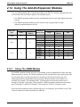
2.14 Using The Add-On Expansion Modules
You can install optional add-on expansion modules to the DSU II common equipment base unit
to increase the line and station capacity of an installed system.
• The JM408 expansion module provides an additional four lines and eight digital proprietary
stations.
• The JM008 expansion module provides interface and ring generation for eight
industry-standard telephone devices.
Base Unit
Type
Base Unit Capacity
System
Lines
Stations
J0408
4
8
J0816
8
16
J1632
2.14.1
16
32
Expansion
Module Type
one JM408
one JM008
one JM408
two JM408
one JM008
two JM008
one JM408 and
one JM008
one JM408
two JM408
one JM008
two JM008
one JM408 and
one Jm008
Total System Capacity
System
Lines
ISTs
Stations
8
16
4
8
8
12
24
16
32
8
16
8
8
16
16
12
24
8
20
24
16
16
40
48
32
32
8
16
20
40
8
Using The JM408 Module
The JM408 expansion module provides to an installed system an additional four lines and eight
digital proprietary stations. The default numbering of the expanded lines and stations begin with
the next higher line or station port number from that provided by the host base unit. The
numbering continues sequentially from top module to bottom module if two modules are
installed. For example: The defaulted 8-line, 16-station base unit provides station ports 10
through 25 and lines 1 through 8. When installed, a JM408 expansion module provides station
ports 26 through 33 and lines 9 through 12 thus creating a 12 line by 24 station system.
Each expansion module provides a tip and ring pair as an emergency power failure circuit. This
circuit is connected to the first module-provided line.
Installing The DSU II Digital Telephone System 2 – 41
IMI66–132
DSU II Digital Telephone System
Connecting Lines To The JM408 Expansion Module
The expansion module’s line connections are available at two modular jacks. When facing the
jack openings, lines 1 and 2 are provided by the jack on the right and lines 3 and 4 are provided
by the jack on the left.
Line Jack
1
2
Pin
Number
1
2
3
4
5
6
1
2
3
4
5
6
Connection
No Connection
Line 2M Tip
Line 1M Tip
Line 1MRing
Line 2M Ring
No Connection
No Connection
Line 4M Tip
Line 3M Tip
Line 3M Ring
Line 4M Ring
No Connection
2 – 42 Installing The DSU II Digital Telephone System
Telephone
Number
DSU II Digital Telephone System
IMI66–132
Connecting Stations To The JM408 Expansion Module
The station connections are available at a 50-pin connector.
25-Pair Connections
Wire Color
Pair
White-Blue
Blue-White
White-Orange
Orange-White
White-Green
Green-White
White-Brown
Brown-White
White-Slate
Slate-White
Red-Blue
Blue-Red
Red-Orange
Orange-Red
Red-Green
Green-Red
Red-Brown
Brown-Red
Red-Slate
Slate-Red
Black-Blue
Blue-Black
Black-Orange
Orange-Black
Black-Green
Green-Black
Black-Brown
Brown-Black
Black-Slate
Slate-Black
Yellow-Blue
Blue-Yellow
Yellow-Orange
Orange-Yellow
Yellow-Green
Green-Yellow
Yellow-Brown
Brown-Yellow
Yellow-Slate
Slate-Yellow
Violet-Blue
Blue-Violet
Violet-Orange
Orange-Violet
Violet-Green
Green-Violet
Violet-Brown
Brown-Violet
Violet-Slate
Slate-Violet
1
2
3
4
5
6
7
8
9
10
11
12
13
14
15
16
17
18
19
20
21
22
23
24
25
Clip
Pin No.
Term.
26
1
1
2
27
3
2
4
28
5
3
6
29
7
4
8
30
9
5
10
31
11
6
12
32
13
7
14
33
15
8
16
34
17
9
18
35
19
10
20
36
21
11
22
37
23
12
24
38
25
13
26
39
27
14
28
40
29
15
30
41
31
16
32
42
33
17
34
43
35
18
36
44
37
19
38
45
39
20
40
46
41
21
42
47
43
22
44
48
45
23
46
49
47
24
48
50
49
25
50
Two-Wire Connections
Station Connections
Pair
Wire Color
Station
Signal Path
Green
Red
Green
Red
Green
Red
Green
Red
Green
Red
Green
Red
Green
Red
Green
Red
1M
Signal Path
Signal Path
Signal Path
Signal Path
Signal Path
Signal Path
Signal Path
Location
2M
3M
4M
5M
6M
7M
8M
Spare Pair
Signal Path
Tip
Ring
Power Fail Station
Installing The DSU II Digital Telephone System 2 – 43
IMI66–132
2.14.2
DSU II Digital Telephone System
Using The JM008 Module
The JM008 expansion module provides an interface for a wide variety of industry-standard
telephone (IST) equipment such as 500 and 2500-type telephones, cordless telephones, voice
mail systems, answering machines, FAX machines, and data modems.
Each IST port drives a load with a maximum ringer equivalence number (REN) of 2.0. Check
the REN number of the connected IST equipment so you do not exceed the capacity of the IST
port. Improper operation may result if you exceed the REN maximum.
The default numbering of the expansion module stations begin with the next higher station port
number from that provided by the host base unit. The numbering continues sequentially from top
module to bottom module if two modules are installed. For example: The defaulted 8-line,
16-station base unit provides station ports 10 through 25. When installed, a JM008 expansion
module provides station ports 26 through 33. A second JM008, when installed in the bottom
mounting location, provides station ports 34 through 41.
CAUTION
If you install both a JM408 and a JM008 on the same cabinet, you must install the JM408 at
the upper expansion module location or the lines provided by the JM408 will not function.
When you install the JM008 and connect IST devices to it, there are several programming
requirements that you must consider. Refer to Chapter 3, Section 3.10 for complete details.
2 – 44 Installing The DSU II Digital Telephone System
DSU II Digital Telephone System
IMI66–132
Connecting Stations To The JM008 Module
The station connections are available at a 50-pin connector.
25-Pair Connections
Wire Color
White-Blue
Blue-White
White-Orange
Orange-White
White-Green
Green-White
White-Brown
Brown-White
White-Slate
Slate-White
Red-Blue
Blue-Red
Red-Orange
Orange-Red
Red-Green
Green-Red
Red-Brown
Brown-Red
Red-Slate
Slate-Red
Black-Blue
Blue-Black
Black-Orange
Orange-Black
Black-Green
Green-Black
Black-Brown
Brown-Black
Black-Slate
Slate-Black
Yellow-Blue
Blue-Yellow
Yellow-Orange
Orange-Yellow
Yellow-Green
Green-Yellow
Yellow-Brown
Brown-Yellow
Yellow-Slate
Slate-Yellow
Violet-Blue
Blue-Violet
Violet-Orange
Orange-Violet
Violet-Green
Green-Violet
Violet-Brown
Brown-Violet
Violet-Slate
Slate-Violet
Clip
Pair Pin No.
Term.
26
1
1
1
2
27
3
2
2
4
28
5
3
3
6
29
7
4
4
8
30
9
5
5
10
31
11
6
6
12
32
13
7
7
14
33
15
8
8
16
34
17
9
9
18
35
19
10
10
20
36
21
11
11
22
37
23
12
12
24
38
25
13
13
26
39
27
14
14
28
40
29
15
15
30
41
31
16
16
32
42
33
17
17
34
43
35
18
18
36
44
37
19
19
38
45
39
20
20
40
46
41
21
21
42
47
43
22
22
44
48
45
23
23
46
49
47
24
24
48
50
49
25
25
50
Two-Wire Connections
Pair
Signal Path
Signal Path
Signal Path
Signal Path
Signal Path
Signal Path
Signal Path
Signal Path
Station Connections
Connection
Tip
Ring
Tip
Ring
Tip
Ring
Tip
Ring
Tip
Ring
Tip
Ring
Tip
Ring
Tip
Ring
Station
Location
1M
2M
3M
4M
5M
6M
7M
8M
Spare Pairs
Installing The DSU II Digital Telephone System 2 – 45
IMI66–132
DSU II Digital Telephone System
Checking Industry-Standard Telephone Connections To The JM008 Module
When you connect industry-standard telephones to the JM008 expansion module, the maximum
distance allowed from the common equipment to the telephone is 1500 feet if you use #24 gauge
or larger, twisted pair cable.
Check the installation of industry-standard telephones for proper operation by performing the
following voltage measurements under the conditions listed:
– have both the common equipment and the stations connected to the station connector block,
– have bridging clips installed on the connector block,
– have the system powered and operational.
Measure DC voltage across the tip and ring pair of each installed industry-standard telephone
with a DC voltmeter. You should read: +24 volts DC +/- 2 volts.
Call each industry-standard telephone to stimulate the ring generator assembly, and measure the
AC ringing voltage across the tip and ring pair of each called telephone.
You should read: 55 volts AC +/- 5 volts.
If your measured voltages are different from the values shown herein, it could indicate a wiring
error or equipment problem.
2 – 46 Installing The DSU II Digital Telephone System
DSU II Digital Telephone System
IMI66–132
Installing An OPX Long Loop Adapter With The JM008
You must use an OPX long loop adapter if you wish to adapt the JM008’s IST station port to
support an off-premise IST application. An OPX long loop adapter connects to a single
telephone line and can greatly extend the line’s loop length (the Proctor Model 46222 adapter*,
for example, can extend line length to 30,000 feet).
*Proctor & Associates Company, Redmond WA
CAUTION
When you connect an OPX long loop adapter to an off-premise extension (OPX), you must
install primary protectors in series with the tip/ring pair of the telephone line that is routed to
the OPX. This action is necessary to protect both the user and the equipment from transient
voltage spikes that can travel through the cable. The telephone company offers basic
protection against this condition; however, that protection is usually designed to safeguard the
central office circuits and you cannot rely upon it to protect common equipment. To help
insure that external over-voltage surges do not damage the system, installation specialists
recommend that you install and properly ground gas discharge tubes or similar primary
protection devices on the telephone line that routes between the adapter and the OPX.
To install the OPX long loop adapter:
• Follow manufacturer’s instructions for unpacking, inspecting, mounting and wiring the
adapter unit.
• Plug a modular cable into the system jack on the adapter and connect the opposite end of
the cable to the JM008’s station port.
• Plug a modular cord into the telephone jack on the adapter and connect the opposite end of
the cord to the OPX line.
• Plug the adapter power cord into a standard 117 VAC, 3-wire electrical outlet.
Installing The DSU II Digital Telephone System 2 – 47
IMI66–132
2.14.3
DSU II Digital Telephone System
Installing An Add-On Expansion Module
Each JM408 or JM008 add-on expansion module measures 15.5" wide x 9.4" high x 1.6" wide
and weighs approximately 4 pounds. The modules are designed so that you can attach them to
the base unit and connect them to it via cabling.
NOTE: If you plan to upgrade the system software at the same time that you add expansion
modules, add the expansion modules first by following steps 1 through 11. Then,
after you have installed the expansion modules and programmed for the new stations
and line ports, upgrade the software as described in the discussion titled, Loading
And Up-Grading The System Software.
To install an expansion module to a base unit, follow the procedure detailed in steps 1–11.
CAUTION
You must always connect the first module to the top location on the base unit.
1. Disconnect both AC power and external battery back-up power from the system.
2. Remove and set aside nameplate from base unit. This action exposes internal cable connector
on base unit circuit board.
3. Reach through opening in base unit and mate module cable plug with base unit circuit board
connectors.
4. Push excess cable inside base unit housing through connector opening.
5. Install expansion module in place on all four mounting holes. Be sure excess cable is not
pinched between add-on module and base unit.
6. Pull module down to latch in place.
7. Use appropriate screw driver to tighten module securing screw into base unit threaded
fastener.
8. Snap nameplate into slots on top of module housing.
9. Attach #10 or #12 insulated, solid copper wire between the frame ground stud on the
expansion module and the frame ground stud on the common equipment cabinet.
10. Reconnect the power to the system.
11. Refer to Chapter 3, and perform configuration programming for new station and line ports.
2 – 48 Installing The DSU II Digital Telephone System
DSU II Digital Telephone System
IMI66–132
Typical Base Unit
(8-Line, 16-Station Base Unit)
Nameplate
(Remove to expose base
unit connectors)
Top
Location
Upper Mounting Holes
(2 Places)
Lower Mounting Holes
(2 Places)
Bottom
Location
cajs111.cdr
Connecting Cable
and Plug
Securing
Screw
Ground
Modules
to Base
Unit
Snap Slots for
Nameplate
Ground Base Cabinet
To Earth Ground.
Typical Add-On Module
Installing The Add-On Expansion Module
Installing The DSU II Digital Telephone System 2 – 49
IMI66–132
DSU II Digital Telephone System
2.15 Checking The System Installation
The system operating features are set to default conditions at initial power-up. These conditions
provide a basic operating system with a known set of parameters, and you should check out the
system with the default conditions in place. At any time while the system is operating, you can
reset default conditions from station port 10 or 12 following the instructions provided in chapter
3, Programming.
2.15.1
Checking The Resistance
Measure the resistance at the station connector blocks under the following conditions.
• AC power cord disconnected from electrical outlet.
• Common equipment connected to station connector blocks.
• Stations wired and wiring punched down on blocks.
• Bridging clips removed from blocks to isolate stations from common equipment.
Measure the resistance of each installed station and wiring from the station side of the connector
blocks. Resistance values will vary with cable length and station type but should be within the
following limits:
• Greater than 700 KΩ
2.15.2
Checking The Voltage
Make the following voltage measurements at the station connector blocks under the following
conditions:
• Bridging clips installed
• AC power connected to the common equipment
Measure the voltage across the signal pair. The measured voltage for proprietary telephones must
be within the following limits:
• 28–36 VDC
NOTE: Refer to Section 2.14.2 for information on testing industry-standard telephones
connected through the JM008 expansion module.
2 – 50 Installing The DSU II Digital Telephone System
DSU II Digital Telephone System
2.15.3
IMI66–132
Checking The General Operating Conditions
1. Check the green light emitting diode (LED) system status indicator. Be sure that it is on
steady. If it is off or flashing, refer to the paragraph titled Checking the System Status
Indicator.
2. Refer to the user’s guide for operating information and perform a general operational test of
the system by exercising the features from station port 10 or 11. Operational parameters are
per the system default conditions as detailed in Chapter 4 until class of service programming
is performed.
3. Once the basic system is verified as operational, perform the class of service programming as
described in Chapter 3.
2.16 Isolating Failures
Section 2.17 will help you to find and identify problems that might occur in the digital telephone
system.
2.16.1
Checking The System Status Indicator
A green LED located on the common equipment cabinet is the system status indicator. This
indicator light comes on when power is supplied to the system. If the indicator flashes after
power up, it signals that the processor has failed or that the software is not operating. Unplug and
reconnect the AC power to the power supply and observe the LED indication. If it still shows a
flashing indication, equipment replacement may be necessary.
2.16.2
Testing The Stations
To test the multiline stations for proper operation:
1. Disconnect line cord at station base then reconnect it.
2. On DigiTech telephones, press and hold the MUTE button.
On Impact and Impression telephones, press and hold 1 on the keypad.
Station will automatically perform self test routine.
3. Release test button as soon as test begins. Sequence of test is as follows:
a. indicators will light in sequence,
b. ringer will sound—be sure volume is set to low or high,
c. indicators and ringer will then turn off at the same time.
4. Replace any station that does not pass the self test.
Installing The DSU II Digital Telephone System 2 – 51
IMI66–132
DSU II Digital Telephone System
2.17 Loading And Up-Grading The System Software
The DSU II contains flash memory that you load with operating software when you install the
system and later re-load with software up-grades as they become available.
The operating software package consists of three parts: The boot-loader EPROMs that is
factory-installed as part of the system, and the software key and software disks that you order
separately. The software disks include the boot loader interface disk and the operating software
disks.
2.17.1
Introducing The Software Key
The software key is a hardware device to un-lock the DSU II so it can accept the system
operating software. Factory technicians program and initialize the software key, and make it
available in several different configurations.
The configurations are as listed below:
DSUII–SW01
DSUII–SW05
DSUII–SW10
DSUII–SW25
The configurations control the number of times that you can use a key to load or up-grade
operating software into a system; however, it does not matter which DSU II system you load.
(For example, with a DSUII–SW01 key, you can load any DSU II system one time; however,
with the DSUII–SW25, you can load or up-grade one system 25 times or load 25 different
systems one time—your choice.)
2 – 52 Installing The DSU II Digital Telephone System
DSU II Digital Telephone System
IMI66–132
Serial Ports
9-Pin D Connector
25-Pin D Connector
Modular To EIA Adapter
Connect To Serial Port
(Both 9-Pin and 25-Pin
adapters are available.)
4-Conductor Line Cord
Connect To
COM 1 Port
On DSU II
Parallel Port
25-Pin D Connector
Rear View of Typical
Personal Computer (PC)
Security Key
Connect To Computer's
Parallel Port
CAJS031j.cdr
Connecting The Security Key
2.17.2
Introducing The Software Disks
There are several standard 3.5-inch magnetic diskettes for each software part number. This group
of diskettes include the boot loader interface and the system operating software. You place these
diskettes (commonly referred to as floppy disks), into your personal computer (PC) in a certain
order just as you would any set of program disks.
CAUTION
The system operating software is unique for each of the three system sizes. Be sure that you
load the correct system software for the size system that you are installing.
Installing The DSU II Digital Telephone System 2 – 53
IMI66–132
2.17.3
DSU II Digital Telephone System
Loading The Software
Installing The Bootloader Interface
You must install the boot loader interface on your PC before you can install the system operating
software.
Installing The Bootloader Interface Software With Windows 95*
1. Insert the bootloader interface disk (labeled disk1) in your PC’s disk drive.
2. From the Start menu, select Run.
3. At the prompt line, type: <drive>:\disk1\setup where <drive> is the letter of your source disk
drive.
4. Click Ok. The Bootloader Interface installation window appears.
NOTE: Alternately, you can use the Explorer View to navigate to the source <drive> and
then to the disk1 folder. Once there, double click on setup.exe and the Bootloader
Interface installation window appears.
5. Remove the bootloader interface disk from you computer’s disk drive.
6. From the Bootloader Interface load window, follow the on-screen prompts to finish loading
the software. The installation creates a DSU II BTLDR I/F window complete with
appropriate icons.
NOTE: Your PC’s screen may now show the DSU II BTLDR I/F folder; however, if it does
not: select Start, then select Programs, and then navigate to DSU II BTLDR I/F
folder.
7. From the DSU II BTLDR I/F window, double click on the Install SKey Driver icon.
8. Select Express and follow the on-screen prompts.
9. When you reach the prompt to restart windows, do so.
*Windows 95 is a registered trademark of Microsoft Corporation, Redmond, Washington
2 – 54 Installing The DSU II Digital Telephone System
DSU II Digital Telephone System
IMI66–132
Installing The Bootloader Interface Software With Windows 3.1* Or Windows For Workgroups 3.11*
1. Insert the bootloader interface disk (labeled disk1) in your PC’s disk drive.
2. From the File Manager menu, select Run.
3. At the prompt line, type: <drive>:\disk1\setup where <drive> is the letter of your source disk
drive.
4. Click Yes. The Bootloader Interface installation window appears.
NOTE: Alternately, you can use the File Manager to navigate through its tree view to the
source <drive> and then to the disk1 folder. Once there, double click on setup.exe
and the Boot loader Interface installation window appears.
5. Remove the boot loader interface disk from you computer’s disk drive.
6. From the Boot loader Interface load window, follow the on-screen prompts to finish loading
the software. The installation creates a DSU II BTLDR I/F folder complete with appropriate
icons.
NOTE: Your PC’s screen may now show the DSU II BTLDR I/F folder; however, if it does
not: use the program manager to navigate to DSU II BTLDR I/F group.
7. From the DSU II BTLDR I/F window, double click on the Install SKey Driver icon.
8. Select Express and follow the on-screen menu prompts.
9. When you reach the prompt to restart windows, do so.
*Windows 3.1 and Windows For Workgroups 3.11 area registered trademarks of Microsoft Corporation, Redmond, Washington
Installing The DSU II Digital Telephone System 2 – 55
IMI66–132
DSU II Digital Telephone System
Un-installing The Bootloader Interface
The software provides a means by which you can un-install it if you wish.
For Windows 95 operating systems,
1. From the Start menu, select Programs, and navigate to the DSU II BTLDR I/F folder.
2
Double click on the Unstall icon.
3. In the event that you were accessing the DSU II BTLDR I/F folder and its contents, you may
need to manually delete the folder and its contents. From Explorer view, navigate through
<drive> to WINDOWS, then to START-MENU, then to PROGRAMS, and finally to DSU II
BTLDR I/F. From there, delete all short-cuts associated with the bootloader interface.
For Windows 3.1 and Windows For Workgroups 3.11,
From the Program Manager, navigate to DSU II BTLDR I/F, and double click the Uninstall
icon.
Installing The System Operating Software
CAUTION
In this software loading sequence, the system will prompt you to save the class of service data
base. ALWAYS SAVE THE DATA BASE FIRST before you proceed with the software load.
Saving the data base first ensures that you will have it available should something go wrong
during the software loading procedure. Later, after you have finished loading the system
software, master clear the system and reload the data base that you saved before you loaded
the software.
Saving The Class Of Service Data Base (Using An XMODEM-Type Communications Program)
Use the PC and an XMODEM-type communications software program to save the DSU II
system’s class of service data base before you load the software. The following procedure
illustrates a typical data base down-load using PROCOMM (produced by Datastorm
Technologies Inc.). Other software programs are also available that you can use for this purpose.
1. When the PC display prompts for a password, type I✳746✳ or the current system password
and press RETURN (This causes main COS programming menu to be displayed).
2. From main menu, make all selections necessary to perform class of service programming
then return to the main menu.
3. From main menu, press 1 and RETURN (This causes system COS programming menu to be
displayed).
2 – 56 Installing The DSU II Digital Telephone System
DSU II Digital Telephone System
IMI66–132
4. From the system menu, press 4 and RETURN (This causes load/save menu to be
displayed.) From load/save menu, you can down-load the COS data base to your PC
(usually to some temporary location on your hard drive).
To down-load the data base,
(a) press 1 and RETURN,
(b) press PAGE DOWN,
(c) press 1 to choose XMODEM protocol,
(d) type destination file name for the down-loaded data base—include destination
drive (for example, C:\ cust.001)
(e) press RETURN. The data base automatically down-loads to the destination file.
To down-load speed dials and auto dials,
(a) press 3 and RETURN,
(b) repeat above steps b–e.
To up-load the data base after you have up-graded the system operation software and
master-cleared the system,
(a) press 2 then RETURN
(b) press PAGE UP
(c) press 1 to choose XMODEM protocol
(e) type file name of saved COS data—include source drive if necessary
(f) press RETURN. The data base is automatically up-loads to the DSU II system.
To up-load speed dials and auto dials,
(a) press 4 and RETURN,
(b) repeat above steps b–f.
If the up-load completes properly, the screen displays: Xmodem transfer complete, no errors.
5. Return to the main menu and log off.
Installing The DSU II Digital Telephone System 2 – 57
IMI66–132
DSU II Digital Telephone System
Loading The System Operating Software (Using The DSU II Bootloader Interface)
1. Connect the security key to the parallel port on the PC.
NOTE: If you wish to view the available up-grade count and the system type supported by the
security key, select Key from the main menu and then select View.
2. Install the system operating software disk (labeled disk2) in your PC’s disk drive.
(Alternately, you could have pre-loaded the disk’s contents into a file location on your PC’s
hard drive.)
3. With Windows 3.1 click the boot loader icon to open the DSU II BTLDR I/F window and
from there click the Boot loader Interface icon.
With Windows 95, select Start, Programs, DSU II BTLDRI_F, and DSU II Boot loader
Interface. The DSU II Boot loader Interface window will open.
4. From the DSU II Boot loader Interface window, select the System drop-down menu, and
then select Upgrade.
5. Follow the on-screen prompts until you reach the Logon Dialog window.
6. At the Logon Dialog window, select the appropriate user type, and type I✳746✳ or your
current system programming password.
7. Follow the on-screen prompts until you reach the appropriate DSU II System Binary File
Selection Dialog box.
8. Use the Drive pull-down menu to select the location where the DSU II System Binary File
resides.
9. Navigate to and then select the appropriate DSU II System Binary File displayed in the File
Selection Dialog box. The system software load automatically begins. A typical load will
take approximately nine minutes.
2 – 58 Installing The DSU II Digital Telephone System
DSU II Digital Telephone System
IMI66–132
Master Clearing The System
After you load the system operating software, master clear the system. Master clearing returns
the entire system configuration to factory settings and clears all stored auto and speed dial
numbers.
NOTE: Do not do this unless you want to clear all of the programmed data base.
1. Type the password I✳746✳ (this will get you into the main menu) and RETURN.
2. Press 1 for System C.O.S. and RETURN.
3. Press 1 for System Defaults and RETURN.
4. Press 8 for Master Clear System Data and RETURN.
5. Press y to confirm and RETURN.
6. Press CTRL C to return to main menu and RETURN.
7. Up-load the class of service data base that you saved before you loaded the system operating
software (see the previous paragraph titled Saving The Class Of Service Data Base for
up-loading procedure.
Installing The DSU II Digital Telephone System 2 – 59