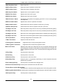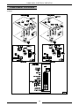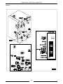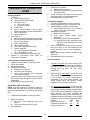
1
SERVICE MANUAL
GAS COMBI
OVENS
MODEL
ML
VC10FGP
52444
VC10HGP
52441
VC20HGP
52442
VC10HGP SHOWN
- NOTICE This Manual is prepared for the use of trained Vulcan Service
Technicians and should not be used by those not properly
qualified. If you have attended a Vulcan Service School for this
product, you may be qualified to perform all the procedures
described in this manual.
This manual is not intended to be all encompassing. If you have
not attended a Vulcan Service School for this product, you should
read, in its entirety, the repair procedure you wish to perform to
determine if you have the necessary tools, instruments and skills
required to perform the procedure. Procedures for which you do
not have the necessary tools, instruments and skills should be
performed by a trained Vulcan Service Technician.
Reproduction or other use of this Manual, without the express
written consent of Vulcan-Hart, is prohibited.
VULCAN-HART COMPANY, P.O. BOX 696, LOUISVILLE, KY 40201-0696
Form 24578 (1/97)
TEL. (205)778-2791
COMBI OVEN
TABLE OF CONTENTS
GENERAL . . . . . . . . . . . . . . . . . . . . . . . . . . . . . . . . . . . . . . . . . . . . . . . . . . . . . . . . . . . . . . . . . . . . . . . . . . . . . 3
Introduction . . . . . . . . . . . . . . . . . . . . . . . . . . . . . . . . . . . . . . . . . . . . . . . . . . . . . . . . . . . . . . . . . . . . . . . . 3
Lubrication . . . . . . . . . . . . . . . . . . . . . . . . . . . . . . . . . . . . . . . . . . . . . . . . . . . . . . . . . . . . . . . . . . . . . . . . . 3
Cleaning . . . . . . . . . . . . . . . . . . . . . . . . . . . . . . . . . . . . . . . . . . . . . . . . . . . . . . . . . . . . . . . . . . . . . . . . . . 3
Tools . . . . . . . . . . . . . . . . . . . . . . . . . . . . . . . . . . . . . . . . . . . . . . . . . . . . . . . . . . . . . . . . . . . . . . . . . . . . . 3
Specifications . . . . . . . . . . . . . . . . . . . . . . . . . . . . . . . . . . . . . . . . . . . . . . . . . . . . . . . . . . . . . . . . . . . . . . 3
Operation - See Installation and Operation Manual . . . . . . . . . . . . . . . . . . . . . . . . . . . . . . . . . . . . . . . . N/A
REMOVAL AND REPLACEMENT OF PARTS . . . . . . . . . . . . . . . . . . . . . . . . . . . . . . . . . . . . . . . . . . . . . . . . . 4
Rack Guide/ Filter/Exhaust Assembly . . . . . . . . . . . . . . . . . . . . . . . . . . . . . . . . . . . . . . . . . . . . . . . . . . . . 4
Covers and Panels . . . . . . . . . . . . . . . . . . . . . . . . . . . . . . . . . . . . . . . . . . . . . . . . . . . . . . . . . . . . . . . . . . . 5
Oven Temperature Probe . . . . . . . . . . . . . . . . . . . . . . . . . . . . . . . . . . . . . . . . . . . . . . . . . . . . . . . . . . . . . 6
Control Board . . . . . . . . . . . . . . . . . . . . . . . . . . . . . . . . . . . . . . . . . . . . . . . . . . . . . . . . . . . . . . . . . . . . . . . 7
Relay Board . . . . . . . . . . . . . . . . . . . . . . . . . . . . . . . . . . . . . . . . . . . . . . . . . . . . . . . . . . . . . . . . . . . . . . . . 7
Blower and Motor . . . . . . . . . . . . . . . . . . . . . . . . . . . . . . . . . . . . . . . . . . . . . . . . . . . . . . . . . . . . . . . . . . . . 8
Cavity Burner . . . . . . . . . . . . . . . . . . . . . . . . . . . . . . . . . . . . . . . . . . . . . . . . . . . . . . . . . . . . . . . . . . . . . . . 9
Orifice (Cavity Burner) . . . . . . . . . . . . . . . . . . . . . . . . . . . . . . . . . . . . . . . . . . . . . . . . . . . . . . . . . . . . . . . . 9
Ball Valve . . . . . . . . . . . . . . . . . . . . . . . . . . . . . . . . . . . . . . . . . . . . . . . . . . . . . . . . . . . . . . . . . . . . . . . . . 9
Ball Valve Motor . . . . . . . . . . . . . . . . . . . . . . . . . . . . . . . . . . . . . . . . . . . . . . . . . . . . . . . . . . . . . . . . . . . 10
Water Level Probes . . . . . . . . . . . . . . . . . . . . . . . . . . . . . . . . . . . . . . . . . . . . . . . . . . . . . . . . . . . . . . . . . 10
Boiler Drain Pump . . . . . . . . . . . . . . . . . . . . . . . . . . . . . . . . . . . . . . . . . . . . . . . . . . . . . . . . . . . . . . . . . . 10
Vent Motor . . . . . . . . . . . . . . . . . . . . . . . . . . . . . . . . . . . . . . . . . . . . . . . . . . . . . . . . . . . . . . . . . . . . . . . . 11
Boiler Burner . . . . . . . . . . . . . . . . . . . . . . . . . . . . . . . . . . . . . . . . . . . . . . . . . . . . . . . . . . . . . . . . . . . . . . 11
Orifice (Boiler Burner) . . . . . . . . . . . . . . . . . . . . . . . . . . . . . . . . . . . . . . . . . . . . . . . . . . . . . . . . . . . . . . . 11
Boiler . . . . . . . . . . . . . . . . . . . . . . . . . . . . . . . . . . . . . . . . . . . . . . . . . . . . . . . . . . . . . . . . . . . . . . . . . . . . 12
Oven Door . . . . . . . . . . . . . . . . . . . . . . . . . . . . . . . . . . . . . . . . . . . . . . . . . . . . . . . . . . . . . . . . . . . . . . . . 12
Oven Door Hinges . . . . . . . . . . . . . . . . . . . . . . . . . . . . . . . . . . . . . . . . . . . . . . . . . . . . . . . . . . . . . . . . . . 13
Door Handle Switch . . . . . . . . . . . . . . . . . . . . . . . . . . . . . . . . . . . . . . . . . . . . . . . . . . . . . . . . . . . . . . . . . 13
Door Seal . . . . . . . . . . . . . . . . . . . . . . . . . . . . . . . . . . . . . . . . . . . . . . . . . . . . . . . . . . . . . . . . . . . . . . . . . 13
Door Locking Mechanism . . . . . . . . . . . . . . . . . . . . . . . . . . . . . . . . . . . . . . . . . . . . . . . . . . . . . . . . . . . . . 14
Oven Cavity Seal . . . . . . . . . . . . . . . . . . . . . . . . . . . . . . . . . . . . . . . . . . . . . . . . . . . . . . . . . . . . . . . . . . . 15
Oven Cavity Drain Seal . . . . . . . . . . . . . . . . . . . . . . . . . . . . . . . . . . . . . . . . . . . . . . . . . . . . . . . . . . . . . . 15
Air Intake Motor . . . . . . . . . . . . . . . . . . . . . . . . . . . . . . . . . . . . . . . . . . . . . . . . . . . . . . . . . . . . . . . . . . . . 15
SERVICE PROCEDURES AND ADJUSTMENTS . . . . . . . . . . . . . . . . . . . . . . . . . . . . . . . . . . . . . . . . . . . . . .
Combi Steam Operation . . . . . . . . . . . . . . . . . . . . . . . . . . . . . . . . . . . . . . . . . . . . . . . . . . . . . . . . . . . . .
Control Test Mode . . . . . . . . . . . . . . . . . . . . . . . . . . . . . . . . . . . . . . . . . . . . . . . . . . . . . . . . . . . . . . . . . .
Control Configuration Mode . . . . . . . . . . . . . . . . . . . . . . . . . . . . . . . . . . . . . . . . . . . . . . . . . . . . . . . . . . .
Oven Door Adjustment . . . . . . . . . . . . . . . . . . . . . . . . . . . . . . . . . . . . . . . . . . . . . . . . . . . . . . . . . . . . . . .
Service Lights . . . . . . . . . . . . . . . . . . . . . . . . . . . . . . . . . . . . . . . . . . . . . . . . . . . . . . . . . . . . . . . . . . . . .
Sensor Cable and Ground Wire Check . . . . . . . . . . . . . . . . . . . . . . . . . . . . . . . . . . . . . . . . . . . . . . . . . .
Electrode Gap Settings . . . . . . . . . . . . . . . . . . . . . . . . . . . . . . . . . . . . . . . . . . . . . . . . . . . . . . . . . . . . . .
Flame Sensor Circuit Check . . . . . . . . . . . . . . . . . . . . . . . . . . . . . . . . . . . . . . . . . . . . . . . . . . . . . . . . . .
Pressure Switch Check . . . . . . . . . . . . . . . . . . . . . . . . . . . . . . . . . . . . . . . . . . . . . . . . . . . . . . . . . . . . . .
Gas Pressure Adjustment . . . . . . . . . . . . . . . . . . . . . . . . . . . . . . . . . . . . . . . . . . . . . . . . . . . . . . . . . . . .
16
16
16
18
19
20
20
20
20
21
21
ELECTRICAL OPERATION . . . . . . . . . . . . . . . . . . . . . . . . . . . . . . . . . . . . . . . . . . . . . . . . . . . . . . . . . . . . . .
Component Function . . . . . . . . . . . . . . . . . . . . . . . . . . . . . . . . . . . . . . . . . . . . . . . . . . . . . . . . . . . . . . . .
Component Location . . . . . . . . . . . . . . . . . . . . . . . . . . . . . . . . . . . . . . . . . . . . . . . . . . . . . . . . . . . . . . . .
10 Level . . . . . . . . . . . . . . . . . . . . . . . . . . . . . . . . . . . . . . . . . . . . . . . . . . . . . . . . . . . . . . . . . . . . . .
20 Level . . . . . . . . . . . . . . . . . . . . . . . . . . . . . . . . . . . . . . . . . . . . . . . . . . . . . . . . . . . . . . . . . . . . . .
Sequence of Operation - Oven . . . . . . . . . . . . . . . . . . . . . . . . . . . . . . . . . . . . . . . . . . . . . . . . . . . . . . . .
Sequence of Operation - Ignition Module . . . . . . . . . . . . . . . . . . . . . . . . . . . . . . . . . . . . . . . . . . . . . . . . .
Wiring Diagrams (10 Level) . . . . . . . . . . . . . . . . . . . . . . . . . . . . . . . . . . . . . . . . . . . . . . . . . . . . . . . . . . .
Wiring Diagrams (20 Level) . . . . . . . . . . . . . . . . . . . . . . . . . . . . . . . . . . . . . . . . . . . . . . . . . . . . . . . . . . .
22
22
24
24
25
26
27
28
30
TROUBLESHOOTING . . . . . . . . . . . . . . . . . . . . . . . . . . . . . . . . . . . . . . . . . . . . . . . . . . . . . . . . . . . . . . . . . . 32
Oven Troubleshooting . . . . . . . . . . . . . . . . . . . . . . . . . . . . . . . . . . . . . . . . . . . . . . . . . . . . . . . . . . . . . . . 32
Burner Troubleshooting . . . . . . . . . . . . . . . . . . . . . . . . . . . . . . . . . . . . . . . . . . . . . . . . . . . . . . . . . . . . . . 34
© VULCAN 1997
2
COMBI OVEN - GENERAL
GENERAL
INTRODUCTION
TOOLS
The procedures in this manual apply to all models
unless specified otherwise.
Standard
•
Standard set of hand tools.
•
Metric set of hand tools.
•
VOM with AC current tester (any quality VOM
with a sensitivity of at least 20,000 ohms can be
used).
•
Gear puller (to remove fan).
•
Temperature tester (thermocouple type).
•
Manometer
Special
•
Red High Temperature RTV (544313 or 542949)
for door seal and probes.
•
Grounding kit (protects control board if handled)
•
Motor Shaft Centering Tool (359450)
•
White silicone grease (545832) for motor shaft
seal
The gas combi oven models:
•
Comes in two heights - 10 & 20.
•
Comes in two depths - Half / Full.
•
Has a programmable control - P.
LUBRICATION
Fan motor has sealed bearings and requires no
additional lubrication.
Fan motor shaft seal requires lubrication at
replacement.
CLEANING
Overall cleanliness is important to the operation of the
oven, special care should be given to the boiler to
prevent premature failure and malfunctions of
components.
Detailed instructions are included in Operation
Instructions Manual.
SPECIFICATIONS
Electrical
120/60/1
Gas
Supply: Natural - 7"W.C.
Fresh Air: 2"W.C.
BTU
MODEL
GAS TYPE
Propane - 11"W.C.
OVEN
BOILER
TOTAL
10 Level
Half depth
Natural
67,000 BTU/hr
40,000 BTU/hr
107,000 BTU/hr
Propane
69,000 BTU/hr
40,000 BTU/hr
104,000 BTU/hr
10 Level
Full depth
Natural
85,000 BTU/hr
45,000 BTU/hr
130,000 BTU/hr
Propane
70,000 BTU/hr
45,000 BTU/hr
115,000 BTU/hr
20 Level
Half depth
Natural
70,000 BTU/hr
58,000 BTU/hr
128,000 BTU/hr
Propane
70,000 BTU/hr
58,000 BTU/hr
128,000 BTU/hr
Water
Hardness - 5.0 grains hardness/gallon
PH - 6.5 to 8
Pressure - Range: 7.25 to 87 psig
Supply line in-line strainer.
3
GAS COMBI OVEN - REMOVAL AND REPLACEMENT OF PARTS
REMOVAL AND REPLACEMENT OF PARTS
RACK GUIDE/ FILTER
/EXHAUST ASSEMBLY
7.
20 level only. Loosen the wing nuts and lower the
filler panel at the top of the exhaust assembly.
Remove the racks (if equipped).
8.
Push the rack guide to rear of oven to remove
the rack guide tabs from from slots in the exhaust
assembly (10 level).
Lift up on exhaust assembly then pull forward at
bottom to clear the dowel pins.
9.
After lower dowel pins have been cleared,
remove assembly from top pins and remove from
oven.
1.
Turn the oven off.
2.
3.
4.
Lift the rear of the rack guide up and pull the
guide out of the oven cavity.
5.
Lift the filter up, then pull forward to remove the
filter (2 filters for 20 level).
6.
WARNING: DISCONNECT THE ELECTRICAL
POWER TO THE MACHINE AT THE MAIN
CIRCUIT BOX. PLACE A TAG ON THE
CIRCUIT BOX INDICATING THE CIRCUIT IS
BEING SERVICED.
10. Reverse procedure to install.
NOTE: Be sure the bottom of the exhaust
assembly is seated on the dowel pins and
fan direction arrow is pointing to left (facing
oven).
4
GAS COMBI OVEN - REMOVAL AND REPLACEMENT OF PARTS
COVERS AND PANELS
3.
Lower the control panel, when the location pin is
aligned with the slot, move forward .
WARNING: DISCONNECT THE ELECTRICAL
POWER TO THE MACHINE AT THE MAIN CIRCUIT
BOX AND SHUT THE WATER SUPPLY AND GAS
VALVE OFF. PLACE A TAG ON THE CIRCUIT BOX
INDICATING THE CIRCUIT IS BEING SERVICED.
Control Panel (10 Level)
1.
Open the door.
2.
Remove fuse access panel.
3.
Remove 2 screws that secure the control panel
while holding the control panel in place.
4.
Remove the panel from the oven and let hang by
the chain.
CAUTION: The control panel will fall and
could be damaged if not held during removal.
5.
Disconnect the probe lead wires, ribbon cable,
door switch lead wires and the chain.
6.
Reverse procedure to install and adjust as
outlined under “OVEN DOOR ADJUSTMENT” in
“SERVICE
PROCEDURES
AND
ADJUSTMENTS”.
Right Side Panel
4.
Lower the control panel until the top locating pins
are clear of the locating holes.
5.
Hang the control panel by the chain.
6.
Disconnect the probe lead wires, ribbon cable,
door switch lead wires and the chain.
7.
Reverse procedure to install and adjust as
outlined under “OVEN DOOR ADJUSTMENT” in
“SERVICE
PROCEDURES
AND
ADJUSTMENTS”."
1.
Remove 3 screws along the bottom of the panel.
(10 Level)
2.
Pull the rear corner away from the oven and
disconnect the ground wire from the panel.
3.
With the rear corner pulled out to help clear the
air intake filter from the motor, slide the panel to
the rear.
4.
Lower the panel while pulling to the rear, to clear
alignment pins.
5.
Reverse procedure to install.
Control Panel (20 Level)
1.
Open the door.
2.
Remove fuse access panel and remove the
screw holding the control panel.
5
GAS COMBI OVEN - REMOVAL AND REPLACEMENT OF PARTS
Rear Panel
1.
Remove 3 screws along the bottom of the panel.
2.
Pull the left rear corner away from the oven and
disconnect the ground wire from the panel.
3.
Lower the panel to clear alignment pins and
remove from the oven.
4.
OVEN TEMPERATURE
PROBE
WARNING: DISCONNECT THE ELECTRICAL
POWER TO THE MACHINE AT THE MAIN CIRCUIT
BOX. PLACE A TAG ON THE CIRCUIT BOX
INDICATING THE CIRCUIT IS BEING SERVICED.
1.
Remove the rack guide, filter and exhaust
assembly as outlined under “RACK GUIDE/
FILTER/EXHAUST ASSEMBLY”.
2.
Remove the right side and rear panels (plus left
side panel for 20 level) as outlined under
“COVERS AND PANELS”.
3.
Remove the retaining nut from the probe inside
the oven.
Reverse procedure to install.
Left Side Panel
1.
Remove the rear panel as outlined under
“COVERS AND PANELS”.
2.
Disconnect the ground wire and remove the
screws from the rear of the panel.
3.
4.
5.
20 LEVEL SHOWN
4.
Slide the panel to the rear to remove the front
edge of the panel from behind the front panel.
Remove probe through the rear (left side for 20
levels) of the oven cavity.
NOTE: Use high temperature silicone between
the probe and the hole in the oven cavity wall.
Lower the panel to clear alignment pins and
remove from the oven.
Reverse procedure to install.
6
5.
Disconnect the probe leads from the control
board.
6.
Reverse procedure to install.
GAS COMBI OVEN - REMOVAL AND REPLACEMENT OF PARTS
CONTROL BOARD
RELAY BOARD
WARNING: DISCONNECT THE ELECTRICAL
POWER TO THE MACHINE AT THE MAIN CIRCUIT
BOX. PLACE A TAG ON THE CIRCUIT BOX
INDICATING THE CIRCUIT IS BEING SERVICED.
WARNING: DISCONNECT THE ELECTRICAL
POWER TO THE MACHINE AT THE MAIN CIRCUIT
BOX. PLACE A TAG ON THE CIRCUIT BOX
INDICATING THE CIRCUIT IS BEING SERVICED.
CAUTION: Certain components in this system are
subject to damage by electrostatic discharge
during field repairs. A field service ground kit is
available to prevent damage. The field service
grounding kit must be used anytime the control
board is handled.
10 Level
1.
Remove the control panel from the oven as
outlined under “COVERS AND PANELS”.
2.
Remove the screws from the control panel as
outlined under “COVERS AND PANELS”.
3.
Remove the cover from the control panel and
remove the control board.
CAUTION: Certain components in this system are
subject to damage by electrostatic discharge
during field repairs. A field service ground kit is
available to prevent damage. The field service
grounding kit must be used anytime the control
board is handled.
4.
1.
Remove the right side panel as outlined under
“COVERS AND PANELS”.
2.
Disconnect lead wires from the relay board.
3.
Remove the screws that secure the relay board.
4.
Reverse procedure to install.
Reverse procedure to install.
20 Level
1.
Remove the right side panel as outlined under
“COVERS AND PANELS”.
2.
Remove the cover from the back of the control
board and disconnect the wire leads.
3.
Remove the control board from the control panel.
4.
Reverse procedure to install.
7
GAS COMBI OVEN - REMOVAL AND REPLACEMENT OF PARTS
Installation
1. Mount the motor to the back of the oven. Tighten
the bolts enough to hold the motor in place, but
allow some movement.
BLOWER AND MOTOR
Removal
WARNING: DISCONNECT THE ELECTRICAL
POWER TO THE MACHINE AT THE MAIN CIRCUIT
BOX. PLACE A TAG ON THE CIRCUIT BOX
INDICATING THE CIRCUIT IS BEING SERVICED.
1.
Remove the rack guide, filter and exhaust
assembly as outlined under “RACK GUIDE/
FILTER/EXHAUST ASSEMBLY”.
2.
Loosen bolt (one turn) that secures the blower
and install puller.
3.
Tighten the puller, then tap the puller with a
hammer to loosen the blower from the motor
shaft.
4.
2.
Ensure that the motor shaft is centered (use shaft
centering tool) in the motor shaft hole and tighten
mounting bolts.
3.
Remove the shaft centering tool.
4.
Connect the lead wires to the motor.
5.
Install seal and cover as outlined under
“BLOWER MOTOR SHAFT SEAL”.
Remove the bolt, washer and blower from the
motor shaft.
CAUTION: Remove all traces of motor seal grease
from the motor shaft.
NOTE: If only the blower is being removed,
reverse the procedure at this point.
6.
Install the blower wheel.
7.
Install exhaust assembly, filter, and rack guide as
outlined under “RACK GUIDE/FILTER/EXHAUST
ASSEMBLY”.
8.
Install rear panel as outlined under “COVERS
AND PANELS”.
BLOWER MOTOR SHAFT
SEAL
5.
6.
7.
8.
Remove the rear panel as outlined under
“COVERS AND PANELS”.
Disconnect the lead wires from the motor.
Remove the motor from the back of the oven.
Remove the cover plate and seal from inside the
oven cavity.
WARNING: DISCONNECT THE ELECTRICAL
POWER TO THE MACHINE AT THE MAIN CIRCUIT
BOX. PLACE A TAG ON THE CIRCUIT BOX
INDICATING THE CIRCUIT IS BEING SERVICED.
NOTE: You may have to drive the seal out from
the back.
8
1.
Remove blower as outlined under “BLOWER
AND MOTOR”.
2.
Remove motor seal cover plate.
3.
Pry the seal from the recess in the rear oven
wall.
4.
Fill replacement seal cover with white silicone
grease.
5.
Assemble the motor seal with the convex part of
the spring toward the motor.
GAS COMBI OVEN - REMOVAL AND REPLACEMENT OF PARTS
6.
Apply red high temperature RTV to the outer
edge of the seal to help hold it in the recess and
install the seal with the seal cover toward the
oven cavity opening.
6.
CAUTION: Remove all traces of motor seal
grease from the motor shaft.
7.
Remove the burner from inside oven cavity.
NOTE: Seal the burner mounting plate with high
temperature sealant.
Install the spark ignitor and flame sensor and
adjust as outlined under “ELECTRODE
ADJUSTMENT” in “SERVICE PROCEDURES
AND ADJUSTMENTS”.
ORIFICE (CAVITY BURNER)
WARNING: SHUT THE GAS OFF TO THE UNIT.
WARNING: DISCONNECT THE ELECTRICAL
POWER TO THE MACHINE AT THE MAIN CIRCUIT
BOX. PLACE A TAG ON THE CIRCUIT BOX
INDICATING THE CIRCUIT IS BEING SERVICED.
7.
Install the seal cover.
8.
Install exhaust assembly, filter, and rack guide as
outlined under “RACK GUIDE/FILTER/EXHAUST
ASSEMBLY “.
CAVITY BURNER
Remove the back panel as outlined under
“COVERS AND PANELS”.
2.
Disconnect the gas line at the gas/air tube.
3.
Remove the gas valve from the inlet line.
4.
Remove the orifice from the holder.
NOTE: Always replace the fiber washer in the
pipe fittings.
WARNING: DISCONNECT THE ELECTRICAL
POWER TO THE MACHINE AT THE MAIN CIRCUIT
BOX. PLACE A TAG ON THE CIRCUIT BOX
INDICATING THE CIRCUIT IS BEING SERVICED.
1.
1.
5.
Reverse procedure to install.
BALL VALVE
Remove the rack guide, filter and exhaust
assembly as outlined under “RACK GUIDE/
FILTER/EXHAUST ASSEMBLY”.
WARNING: SHUT THE GAS OFF TO THE UNIT.
WARNING: DISCONNECT THE ELECTRICAL
POWER TO THE MACHINE AT THE MAIN CIRCUIT
BOX. PLACE A TAG ON THE CIRCUIT BOX
INDICATING THE CIRCUIT IS BEING SERVICED.
2.
Remove rear panel as outlined under “COVERS
AND PANELS”.
3.
Remove the spark ignitor and the flame sensor
from the oven cavity.
1.
4.
Remove the bolts from the gas pipe flange on
the rear of the oven.
2.
3.
5.
Inside the oven cavity, remove the nuts securing
the burner.
4.
5.
9
Remove the right side and rear panels as
outlined under “COVERS AND PANELS”.
Remove the air intake motor.
Remove the ball valve motor as outlined under
“BALL VALVE MOTOR”, but do not disconnect
the lead wires. You can place the motor to the
side.
Remove the cavity burner gas valve.
6.
Disconnect the gas/air line at the back of the
oven cavity.
Remove the ball valve from the gas/air line.
7.
Reverse procedure to install.
GAS COMBI OVEN - REMOVAL AND REPLACEMENT OF PARTS
BALL VALVE MOTOR
4.
Remove the rear panel as outlined under
“COVERS AND PANELS”.
WARNING: DISCONNECT THE ELECTRICAL
POWER TO THE MACHINE AT THE MAIN CIRCUIT
BOX. PLACE A TAG ON THE CIRCUIT BOX
INDICATING THE CIRCUIT IS BEING SERVICED.
5.
Disconnect the lead wires to the water level
probes.
6.
Remove the hose from the water level regulator.
7.
Remove the probe assembly from the top of the
water level regulator.
8.
Reverse procedure to install.
1.
Remove the rear panel as outlined under
“COVERS AND PANELS”.
2.
Disconnect the lead wires from the motor and
switches.
3.
Remove the motor and switch assembly from the
unit.
BOILER DRAIN PUMP
4.
5.
1.
Turn the unit off and allow the boiler to drain.
2.
WARNING: DISCONNECT THE ELECTRICAL
POWER TO THE MACHINE AT THE MAIN
CIRCUIT BOX. PLACE A TAG ON THE
CIRCUIT BOX INDICATING THE CIRCUIT IS
BEING SERVICED.
3.
Remove the rear panel as outlined under
“COVERS AND PANELS”.
4.
Turn water supply off.
5.
Disconnect lead wires and hoses.
6.
Remove the two bolts from the bottom of the
oven that secure the pump.
7.
Reverse procedure to install.
Remove the bolts from the clamp that connects
the motor to the ball valve.
Reverse procedure to install.
WATER LEVEL PROBES
1.
Turn the unit off and allow the boiler to drain.
2.
WARNING: DISCONNECT THE ELECTRICAL
POWER TO THE MACHINE AT THE MAIN
CIRCUIT BOX. PLACE A TAG ON THE
CIRCUIT BOX INDICATING THE CIRCUIT IS
BEING SERVICED.
3.
Turn water supply off.
10
GAS COMBI OVEN - REMOVAL AND REPLACEMENT OF PARTS
NOTE: When installing the flue, seal the edges
of the metal with high temperature sealant.
VENT MOTOR
WARNING: DISCONNECT THE ELECTRICAL
POWER TO THE MACHINE AT THE MAIN CIRCUIT
BOX. PLACE A TAG ON THE CIRCUIT BOX
INDICATING THE CIRCUIT IS BEING SERVICED.
5.
Disconnect the lead wires from the electrodes
and the ground.
6.
Disconnect the gas line.
1.
Remove the right side panel as outlined under
“COVERS AND PANELS”.
7.
Remove the screws from the burner mounting
plate and remove the burner.
2.
Remove the air intake motor (10 level half size).
8.
Reverse procedure to install.
3.
Disconnect the lead wires from the switch and
motor.
4.
Remove the pin that connects the motor and the
shaft.
5.
Remove the motor and switch assembly from the
oven.
6.
Remove the motor from the mounting bracket.
7.
Reverse procedure to install.
BOILER BURNER
ORIFICE (BOILER BURNER)
1.
Turn the unit off and allow the boiler to drain.
WARNING: SHUT THE GAS OFF TO THE UNIT.
2.
WARNING: DISCONNECT THE ELECTRICAL
POWER TO THE MACHINE AT THE MAIN
CIRCUIT BOX. PLACE A TAG ON THE
CIRCUIT BOX INDICATING THE CIRCUIT IS
BEING SERVICED.
WARNING: DISCONNECT THE ELECTRICAL
POWER TO THE MACHINE AT THE MAIN CIRCUIT
BOX. PLACE A TAG ON THE CIRCUIT BOX
INDICATING THE CIRCUIT IS BEING SERVICED.
1.
Remove the back panel as outlined under
“COVERS AND PANELS”.
WARNING: SHUT OFF THE GAS BEFORE
SERVICING THE UNIT.
3.
4.
2.
Remove the lead wires from the two electrodes.
Remove the right side and rear panels as
outlined under “COVERS AND PANELS”.
3.
Remove the orifice from the holder.
Remove the flue from the boiler.
4.
Reverse procedure to install.
11
GAS COMBI OVEN - REMOVAL AND REPLACEMENT OF PARTS
Disassembly
BOILER
WARNING: DISCONNECT THE ELECTRICAL
POWER TO THE MACHINE AT THE MAIN CIRCUIT
BOX. PLACE A TAG ON THE CIRCUIT BOX
INDICATING THE CIRCUIT IS BEING SERVICED.
WARNING: SHUT OFF
SERVICING THE UNIT.
THE GAS BEFORE
1.
Turn water supply to the boiler off and drain the
boiler.
2.
Remove the right side and rear panels as
outlined under “COVERS AND PANELS”.
3.
Remove the boiler burner as outlined under
“BOILER BURNER”.
1.
Remove the door from the oven as outlined
under “OVEN DOOR”.
2.
Lay the door on a flat surface with the inside of
the door facing up.
3.
Remove the inner glass by removing the four
screws.
Caution: Install the conductive side toward
the front of the oven. To verify the conductive
side, use an ohmmeter. Some resistance will
show between the meter leads depending on
the distance between the meter leads, grease
and/or other substances on the glass.
4.
Remove the light cover and drip tray.
4.
Disconnect all water and drain connections to
boiler.
5.
Remove the screws from the top and bottom
hinges.
5.
Remove insulation from old boiler and separate
the burner box from the boiler.
6.
Remove remaining screws from the inner door
panel.
6.
Reverse procedure to install.
7.
Remove the screws from the bottom of the door.
8.
Remove the inner door panel from the outer door
panel.
9.
Remove the outer glass.
OVEN DOOR
Removal
WARNING: DISCONNECT THE ELECTRICAL
POWER TO THE MACHINE AT THE MAIN CIRCUIT
BOX. PLACE A TAG ON THE CIRCUIT BOX
INDICATING THE CIRCUIT IS BEING SERVICED.
1.
2.
3.
Remove the rear panel as outlined under
“COVERS AND PANELS”. (Ovens with lights)
Disconnect the lead wires to the light at the
terminal block in the left rear corner and route
them so they can be pulled through the hole in
the frame when the door is removed. (Ovens with
lights)
Support the door, remove the screws from each
hinge and remove door.
NOTE: Install the outer glass so the logo can be
read with the door closed.
10. Reverse procedure to install.
11. Adjust the door as outlined under DOOR
ADJUSTMENT” in “SERVICE PROCEDURES
AND ADJUSTMENTS”.
4.
Reverse procedure to install.
12
GAS COMBI OVEN - REMOVAL AND REPLACEMENT OF PARTS
OVEN DOOR HINGES
DOOR HANDLE SWITCH
WARNING: DISCONNECT THE ELECTRICAL
POWER TO THE MACHINE AT THE MAIN CIRCUIT
BOX. PLACE A TAG ON THE CIRCUIT BOX
INDICATING THE CIRCUIT IS BEING SERVICED.
WARNING: DISCONNECT THE ELECTRICAL
POWER TO THE MACHINE AT THE MAIN CIRCUIT
BOX. PLACE A TAG ON THE CIRCUIT BOX
INDICATING THE CIRCUIT IS BEING SERVICED.
1.
Remove and disassemble the door as outlined
under “OVEN DOOR”.
1.
Remove the control panel and let it hang by the
chain as outlined under “COVERS AND
PANELS”.
2.
Remove the light lead wire from the hinge.
(Ovens with lights only)
NOTE: Strip 3 inches of the shielding away from
the wires at the terminal end to allow the
terminals to be fed through the hinge one at a
time.
2.
Remove the screws that secure the door switch
mounting plate.
3.
4.
Disconnect the switch lead wires.
Remove the switch from the bracket.
5.
Reverse procedure to install.
3.
Remove the cotter pins from the shaft and
remove the shaft from the hinges.
DOOR SEAL
1.
Turn the oven off.
2.
Open the oven door.
3.
4.
Remove seal from the edge of the inside glass.
Clean the edge of the glass, remove the old
adhesive.
Apply red silicone to the replacement seal and
install the seal to the glass edge. The vent holes
must be installed to the outside to allow the seal
to contract when the door is closed.
5.
4.
6.
Reverse procedure to install.
13
Adjust door closure, if necessary, as outlined
under “OVEN DOOR AND DOOR LOCK
ADJUSTMENT” in “SERVICE PROCEDURES
AND ADJUSTMENTS”.
GAS COMBI OVEN - REMOVAL AND REPLACEMENT OF PARTS
DOOR LOCKING
MECHANISM
2.
Remove the motor, gear box and switch
assembly from the locking mechanism.
3.
Remove the two bolts from
mechanism.
4.
The springs, locking arm and bushings can be
removed.
5.
Reverse procedure to install.
WARNING: DISCONNECT THE ELECTRICAL
POWER TO THE MACHINE AT THE MAIN CIRCUIT
BOX. PLACE A TAG ON THE CIRCUIT BOX
INDICATING THE CIRCUIT IS BEING SERVICED.
Replacement
1. Remove the right side panel as outlined under
“COVERS AND PANELS”.
2.
Remove the relay board. (Model 10 only).
3.
Disconnect the lead wires to the motor and
switches.
4.
Remove the nuts from the mounting studs and
remove the assembly from the oven.
5.
Remove the spring and positioning plate from the
locking arm.
6.
Reverse procedure to install and adjust as
outlined under “OVEN DOOR AND DOOR LOCK
ADJUSTMENT” in “SERVICE PROCEDURES
AND ADJUSTMENTS”.
Disassembly
1.
Remove the three screws that secure the motor
and switch assembly.
14
the locking
GAS COMBI OVEN - REMOVAL AND REPLACEMENT OF PARTS
OVEN CAVITY SEAL
OVEN CAVITY DRAIN SEAL
WARNING: DISCONNECT THE ELECTRICAL
POWER TO THE MACHINE AT THE MAIN CIRCUIT
BOX. PLACE A TAG ON THE CIRCUIT BOX
INDICATING THE CIRCUIT IS BEING SERVICED.
WARNING: DISCONNECT THE ELECTRICAL
POWER TO THE MACHINE AT THE MAIN CIRCUIT
BOX. PLACE A TAG ON THE CIRCUIT BOX
INDICATING THE CIRCUIT IS BEING SERVICED.
1.
Open the door.
1.
Open the door.
2.
Pull the seal from the groove around the oven
cavity.
2.
Remove the drain cover from the fastener by
lifting up. It is attached by a spring clip.
3.
Push the arrow head tip of the gasket into the
groove. Install the four corners first.
3.
Remove the fastener that secures the drain to
the cavity. This lowers the drain enough to
remove the seal.
4.
Start at the corners and work to the middle of
each side, being careful not to stretch the
replacement gasket.
4.
Remove the “O” ring (seal) from around the drain
opening.
5.
Reverse procedure to install.
5.
Check the door for proper operation and adjust if
necessary, as outlined under “OVEN DOOR AND
DOOR LOCK ADJUSTMENT” in “SERVICE
PROCEDURES AND ADJUSTMENTS”.
AIR INTAKE MOTOR
WARNING: DISCONNECT THE ELECTRICAL
POWER TO THE MACHINE AT THE MAIN CIRCUIT
BOX. PLACE A TAG ON THE CIRCUIT BOX
INDICATING THE CIRCUIT IS BEING SERVICED.
1.
Remove the right side and rear panels as
outlined under “COVERS AND PANELS”.
2.
Remove the boiler flue. (10 level half size)
3.
Remove the hose clamp from the outlet side of
the motor housing.
4.
Remove the screws that secure the air intake
motor plate.
NOTE: Two of the screws also hold the
compartment fan in place.. (10 level half size)
5.
15
Reverse procedure to install.
COMBI OVEN - SERVICE PROCEDURES AND ADJUSTMENTS
SERVICE PROCEDURES AND ADJUSTMENTS
WARNING: CERTAIN PROCEDURES IN THIS SECTION REQUIRE ELECTRICAL TEST OR MEASUREMENTS
WHILE POWER IS APPLIED TO THE MACHINE. EXERCISE EXTREME CAUTION AT ALL TIMES. IF TEST
POINTS ARE NOT EASILY ACCESSIBLE, DISCONNECT POWER, ATTACH TEST EQUIPMENT AND REAPPLY
POWER TO TEST.
COMBI STEAM OPERATION
The combi mode is used when steam needs to be added to a bake mode. The boiler burner operates a percentage
of the bake time depending on the combi setting on the control.
Indicator Lights
(on front panel)
%
Steam
Seconds ON
Seconds OFF
20
16
64
30
24
56
40
32
48
50
40
40
60
48
32
75
60
20
CONTROL TEST MODE
•
•
The test mode can be entered only when the oven is off.
The six test are run in sequence, the test number (1 - 6) is indicated by the position of the illuminated LED in
the bar graph of the combi mode key.
The test are performed in a fixed sequence of:
1. ROM (automatically)
2. RAM (automatically)
3. Displays and LEDs
4. Relays (relay on for max. of 2 seconds)
5. Keyboard
6. Sensor status
To Perform:
1.
To enter the test mode press the “temp”, “temp up” and “temp down” keys simultaneously for 5 seconds.
2.
If a ROM or RAM failure is detected, a failure code (01 = ROM and 02 = RAM) will be displayed on the
temperature display, otherwise the next test will be performed.
3.
The DISPLAY and LED test consists of flashing all displays and LEDs on for 1.5 seconds and off for .7 seconds.
Failure is detected by visual observation. This test cycle will continue until any key is pressed.
16
COMBI OVEN - SERVICE PROCEDURES AND ADJUSTMENTS
4.
5.
The RELAY test consist of selecting a particular relay (numbered between 1 and 11) with the temperature up
and down keys. The selected relay is then energized for a maximum of 2 seconds when the temperature set
key is pressed. The test may be exited at any time by pressing the “off” key and holding for a minimum of 3
seconds.
Code
Relay
Component
Code
Relay
Component
Code
Relay
Component
01
K1
door motor
05
K6
drain pump
09
K8
ignition
module, boiler
02
K2
motorized
vent
06
K4,K6
water solenoid
10
K10
fan motor
03
K3
motorized ball
valve
07
K4,K5
air intake fan
and cavity light
11
K9
N/A
04
K4
main relay
08
K7
ignition module,
cavity burner
The KEYBOARD test consist of pressing each key. With each successful key press, the number of the key is
displayed on the temperature display. Each key is numbered, starting with number 1 (ON) in the upper left
corner of the control.
KEY
6.
Key #
KEY
Key #
KEY
Key #
KEY
Key #
ON
01
Phase
07
Temp Down
13
Enter Up
19
OFF
02
Time
08
Temp Up
14
Reset Cavity Burner
20
Hot Air
03
Time
Down
09
Delta T
15
Reset Boiler Burner
21
Steam
04
Time Up
10
Prog
16
Combi
05
Probe
11
Enter
17
Start/Stop
06
Temp
12
Enter Down
18
The SENSOR STATUS test consist of selecting a particular sensor (numbered between 1 and 11) with the
temperature up and down keys. The selected sensor is then tested when the temperature set key is pressed.
The test may be exited at any time by pressing the “off” key.
Code
Sensor
Code
Sensor
Code
Sensor
01
cavity flame
detection
05
cavity safety t’stat
09
upper water level
02
pressure switch
06
closed position for motorized
ball valve
10
lower water level
03
boiler flame detection
07
opened position for
motorized ball valve
11
motor reset switch
04
door switch
08
closed position for motorized
vent
17
COMBI OVEN - SERVICE PROCEDURES AND ADJUSTMENTS
CONTROL CONFIGURATION MODE
•
•
The configuration mode can be entered only when the oven is off.
Returning to the normal operating mode can be done at any time by pressing the “off” key.
The selection are performed in a fixed sequence of:
1. Number of fan motors. (1 = 10 levels and 2 = 20 levels)
2. Degrees Celsius or Fahrenheit.
3. Date code of software version.
4. Total running time of the oven is displayed in the temperature display.
5. Buzzer sound impulses.
1.
To enter the configuration mode press the “time”, “time up” and “time down” keys simultaneously for 5 seconds.
2.
1 or 2 is displayed. Press “temp up” for 10 level (1); “temp down” for 20 level (2). The blinking letter is the one
that has been selected. Wait 3 seconds after the selection and the control will advance.
3.
C or F is displayed. Press “temp up” for Fahrenheit; “temp down” for Celsius. The blinking letter is the one that
has been selected. Wait 3 seconds after the selection and the control will advance.
4.
The software version code is shown in the time display. The first character is the day code, the second is the
month and the third is the year. Press the up or down arrow key to advance to the next step.
Day coding system
Month coding system
Year coding system
Code
DAY
Code
DAY
Code
Mon.
Code
Mon.
Code
Yr
Code
Yr
0
1
8
16 or 17
1
Jan
9
Sep
0
90
8
98
1
2 or 3
9
18 or 19
2
Feb
A
Oct
1
91
9
99
2
4 or 5
A
20 or 21
3
Mar
B
Nov
2
92
A
00
3
6 or 7
B
22 or 23
4
Apr
C
Dec
3
93
B
01
4
8 or 9
C
24 or 25
5
May
4
94
C
02
5
10 or 11
D
26 or 27
6
Jun
5
95
D
03
6
12 or 13
E
28 or 29
7
Jul
6
96
E
04
7
14 or 15
F
30 or 31
8
Aug
7
97
F
05
5.
HHH is displayed in the time display and the running time is displayed in the temperature display. Press “temp
up” to increase number; “temp down” to decrease number. Press the timer up or down arrow key to advance
to the next step.
6.
bbb is displayed in the time display and the signal code is displayed in the temperature display. Use the
temperature up and down arrow keys to set the buzzer signal code. (000 = continuous and 255 = very slow
intervals)
18
COMBI OVEN - SERVICE PROCEDURES AND ADJUSTMENTS
OVEN DOOR ADJUSTMENT
1.
Turn the oven off.
2.
Loosen the hinge screws enough that you can
move the door but the door will stay in position
when not being moved.
3.
Position the door square with the oven, then
tighten the hinge screws.
6.
With the door in the closed position the roller
should be cradled in the door lock arm hook.
7.
Close the handle. The handle should be centered
in the cut-out of the control panel so the magnet
in the handle will operate the reed switch and not
rub on the control panel.
NOTE: The control panel position can be
adjusted by loosening the bottom screws and
either raising or lowering to center the door
handle.
4.
Position the door with the roller on the strike
against the locking arm. Observe (through the
door glass) the mating of the locking arm with the
roller. The roller should mate at the bottom of the
sloped edge of the locking arm. This allows the
locking arm to be pushed down during closing
and after closing the roller will be positioned in
the hook.
8.
Turn the oven “on”.
9.
The door should be pulled shut and locked in
position to seal the oven opening.
NOTE: If the oven has a light, turn the light on to
help you see the strike.
5.
A.
You can raise or lower the door locking
mechanism to position the locking arm to
the roller.
B.
On 20 Series Ovens, the roller can also be
moved to obtain the adjustment.
Push the door closed and observe the locking
arm. It must not contact the bottom edge of the
slot in the oven door facing while the door is
being closed.
10. The space between the top edge of the door and
the oven should be equal.
A. This space can be adjusted by adding or
removing shims from the door hinges or the
door locking mechanism.
B.
19
(1) If the space is larger at the hinge end,
remove shim(s) from behind the hinges
or from in front of the door locking
mechanism.
(2) If the space is smaller at the hinge end,
add shim(s) behind the hinges or in
front of the door locking mechanism.
If the space is equal, but the oven does not
seal. Remove shims from the hinges and in
front of the door locking mechanism.
COMBI OVEN - SERVICE PROCEDURES AND ADJUSTMENTS
SERVICE LIGHTS
ELECTRODE GAP SETTINGS
There are four lights at along the bottom of the
control. When lit, they tell the operator that the oven
needs service. The lights are, from left to right:
WARNING: DISCONNECT THE ELECTRICAL
POWER TO THE MACHINE AT THE MAIN CIRCUIT
BOX. PLACE A TAG ON THE CIRCUIT BOX
INDICATING THE CIRCUIT IS BEING SERVICED.
1.
Air Intake: Air flow to cavity burner is restricted,
check filter. Turn oven off to reset light.
2.
Cavity Burner Ignition: Flame is not detected,
press reset button above light to reset.
3.
Boiler Burner Ignition: Flame is not detected,
press reset button above light to reset.
4.
Cavity Fan: Fan not operating, remove power
from oven and press reset switch on relay board.
1.
The spark rod gap is 25/64 inch.
NOTE: The right side panel will have to be
removed.
FLAME SENSOR CIRCUIT
CHECK
1.
FLAME SENSOR
INSPECTION
Connect a micro ammeter in series with the
flame signal ground wire. (Use dc scale.)
2.
Restart the system and read the meter. The
flame sensor circuit must be at least 1.5)A and
steady.
3.
If the amp reading is low or unsteady check:
A.
Position of flame sensor electrode.
B.
Bent or damaged electrode.
C.
Connections of flame sensor lead wire.
WARNING: DISCONNECT THE ELECTRICAL
POWER TO THE MACHINE AT THE MAIN CIRCUIT
BOX. PLACE A TAG ON THE CIRCUIT BOX
INDICATING THE CIRCUIT IS BEING SERVICED.
SENSOR CABLE AND
GROUND WIRE CHECK
WARNING: DISCONNECT THE ELECTRICAL
POWER TO THE MACHINE AT THE MAIN CIRCUIT
BOX. PLACE A TAG ON THE CIRCUIT BOX
INDICATING THE CIRCUIT IS BEING SERVICED.
A common ground is required for the burner, spark
ignitor and flame sensor mounting bracket, the “GND”
terminal of the ignition control.
1.
Check for continuity between these ground wire
connections.
20
1.
Flame rod or mounting bracket can not be bent.
2.
Ceramic insulator can not be cracked.
3.
Observe the burner while operating to inspect:
A.
Flame rod must be emerged in the flame.
B.
Approximately 1 inch of the flame rod
should be immersed in the flame.
COMBI OVEN - SERVICE PROCEDURES AND ADJUSTMENTS
PRESSURE SWITCH CHECK
1.
Set the pressure switch dial on 2.
2.
Remove the screw from the test port and attach
a manometer.
3.
Check for 2"W.C.
4.
Move the dial to obtain the 2"W.C.
GAS PRESSURE
ADJUSTMENT
WARNING: DISCONNECT THE ELECTRICAL
POWER TO THE MACHINE AT THE MAIN CIRCUIT
BOX. PLACE A TAG ON THE CIRCUIT BOX
INDICATING THE CIRCUIT IS BEING SERVICED.
1. Ensure the proper orifices are installed in the
burner assembly as outlined under “ORIFICE” in
“REMOVAL AND REPLACEMENT OF PARTS”.
F"
2.
Attach the manometer to the
pressure tap on the gas valve.
NPT outlet
3.
Remove the pressure regulator adjustment cap
of the main gas valve to access the slotted
adjustment screw.
4.
Set up oven to call for heat and adjust pressure
regulator for the proper manifold pressure.
NOTE: ACCURATE GAS PRESSURE
ADJUSTMENTS CAN ONLY BE MADE WITH
THE BURNER RUNNING AND THE GAS ON.
NOTE: Turn adjustment screw clockwise to
increase pressure.
Turn adjustment screw counterclockwise to
decrease pressure.
3½" W.C. for Natural gas.
10" W.C. for LP.
21
COMBI OVEN - ELECTRICAL OPERATION
ELECTRICAL OPERATION
COMPONENT FUNCTION
1A Oven Control . . . . . . .
Manages all functions of oven, takes input signals and performs outputs as
required.
2A Relay Board . . . . . . . .
Takes inputs from control to operate relays that control power to the components.
3A Cavity Burner Ignition Module
Controls and monitors the cavity burner operation.
4A Boiler Ignition Module
Controls and monitors the boiler burner operation.
5A Gas Valve (Cavity) . . .
Controls gas to the cavity burner.
6A Gas Valve (Boiler) . . .
Controls gas to the boiler burner.
F1 Fuse . . . . . . . . . . . . . .
250mA - Protects output to display and control (24 VAC).
F2 Fuse . . . . . . . . . . . . . .
2A - Controls all inputs except cavity blower motor (250 VAC).
F3 Fuse . . . . . . . . . . . . . .
6.3A - Protects the oven fan motor (250 VAC).
F4 Fuse . . . . . . . . . . . . . .
6.3A - Protects the oven circuit on L1 (120 VAC).
F5 Fuse . . . . . . . . . . . . . .
Protects the light circuit.
F6 Fuse . . . . . . . . . . . . . .
250 mA - Protects the low voltage input supply (18 VAC).
F7 Fuse . . . . . . . . . . . . . .
250 mA - Protects the low voltage input supply (18 VAC).
1LT Oven Light . . . . . . . .
Illuminates oven cavity.
1M Vent Motor
Opens and close exhaust port.
........
2M Drain Pump Motor
3M Cooling Fan
..
.......
Empties boiler.
Exhaust component compartment air to cool components.
4M Door Motor . . . . . . . .
Pulls door into and out of lock position.
5M Oven Blower Motor . .
Circulates air through the oven cavity.
6M Cooling Fan
Pulls cool air into component compartment to cool components.
.......
7M Ball Valve Motor . . . .
Moves ball valve into open and close position.
8M Air Intake Motor . . . . .
Circulates outside air through the oven cavity burner gas/air tube.
9M Oven Blower Motor . .
Circulates air through the oven cavity. 20 level only
10M Door Motor . . . . . . .
Pulls door into and out of lock position. Bottom of 20 level
Cavity Probe . . . . . . . . . .
Signals the control, the oven cavity temperature.
Meat Probe . . . . . . . . . . .
Inserted into product. Signals control of internal product temperature.
1SOL Water Valve
Opens when water is needed in the boiler.
.....
22
COMBI OVEN - ELECTRICAL OPERATION
1SW Cavity Motor Reset
Resets relay K10.
2SW Door Mech Switch .
Allows door motor to operate to unlock door.
3SW Door Mech Switch .
Allows door motor to operate to lock door.
4SW Cavity Vent Switch .
Signals control, vent is opened or closed.
5SW Ball Valve Switch . .
Signals control, ball valve is open.
6SW Ball Valve Switch . .
Signals control, ball valve is closed.
7SW Air Pressure Switch
Prevents the cavity burner from operating until 2"W.C. of air is moving through
the air/gas tube.
8SW Door Handle Switch
Signals control, door is in position to be closed.
9SW Door Mech Switch .
Allows bottom door motor to operate to unlock door. (20 Level)
10SW Door Mech Switch
Allows bottom door motor to operate to lock door. (20 Level)
1TAS High Limit T'stat . .
Removes power to cavity burner if oven cavity overheats (manual reset) (650°F).
2TAS High Limit T'stat . .
Removes power to cavity burner if oven cavity overheats (manual reset) (650°F).
3TAS High Limit T'stat . .
Removes 24 volt to boiler ignition module if boiler overheats (auto reset) (275°F).
4TAS High Limit T'stat . .
Removes 24 volt to boiler ignition module if boiler overheats (auto reset) (275°F).
1TB Terminal Block . . . .
Incoming voltage leads are connected at 1TB.
1T Main Transformer . . .
Supplies 18 VAC and 220 VAC.
2T Cavity Ignition Transformer
Supplies 24 VAC to cavity burner ignition module.
3T Boiler Ignition Transformer . . . Supplies 24 VAC to boiler burner ignition module.
Water Level Probes . . . . .
Maintains boiler water level. Water fills until circuit is complete through high level
probe and ground. As water is used, water level drops below low level probe. The
control is signaled by the open circuit. The water solenoid is energized to refill the
boiler.
1K Door Relay . . . . . . . . .
Controls power to door motor.
2K Vent Relay . . . . . . . . .
Controls power to vent motor.
3K Ball Valve Relay
....
Controls power to ball valve motor.
4K Start/Stop Relay
....
Controls power to components used during a mode of operation when the
Start/Sto key is pressed..
5K Air Intake/Light Relay
Controls power to air intake motor and light circuit.
6K Solenoid Valve\Drain Relay Controls power to solenoid valve and drain motor.
7K Cavity Burner Ignition Module Relay
Controls power to transformer that supplies power to the cavity ignition module.
8K Boiler Ignition Module Relay Controls power to transformer that supplies power to the boiler ignition module.
10KCavity Fan Relay
...
Controls power to cavity fan motor.
23
COMBI OVEN - ELECTRICAL OPERATION
COMPONENT LOCATION
10 Level
24
COMBI OVEN - ELECTRICAL OPERATION
20 Level
25
COMBI OVEN - ELECTRICAL OPERATION
4.
SEQUENCE OF OPERATION
- OVEN
5.
Powering Control
1. Conditions
A. Oven installed correctly
B. High limit thermostats closed
C. 120 VAC to oven
1) 18 VAC to control
2) 240 VAC to control
D. Fuses good
E. Door in closed position, but not locked.
Handle positioned over door handle switch.
F. Cavity vent closed
G. Gas and water “on”
2. Turn Oven on.
A. Door closing motor energized; door locked.
B. Ball valve motor operates and positions ball
valve in open position.
C. Cooling fans operate
D. Cavity lights illuminate.
E. Vent motor energized; vent opens.
F. Control energized.
(1) Cavity temperature displayed
(2) Time displays -h --min.
G. Water fill solenoid energized; Boiler fills.
3. Proceed to appropriate Cook Mode for
continuation of sequence.
6.
Combi Mode (Manual)
1. Conditions as described in Powering Control.
2. Set the temperature for the convection mode.
3. Set percentage of steam for combi mode.
A. Press combi mode key 1 to 6 times for a
range of 20 to 75 percent steam.
4. Start/Stop key pressed.
A. Blower motor energized.
B. Oven cavity burner ignition circuit
energized.
C. Boiler burner ignition circuit energized.
(1) Boiler burner is only energized for the
percent of time entered by the combi
mode key.
5. Control monitors oven cavity probe and cycles
the oven burner on the set temperature and
cycles the boiler burner on the percentage of
time set.
NOTE: Both burners could be operated at the
same time.
6. Press Start/Stop key to end mode.
Control Functions
Convection Mode (Manual Operation)
1. Conditions as described in Powering Control.
2. Hot Air key pressed.
3. Set the temperature.
4. Start/Stop key pressed.
A. Blower motor energized.
B. Air intake motor energized.
C. Cavity burner ignition circuit energized.
(See burner sequence)
5. Control monitors oven cavity probe and cycles
the air intake motor and ignition circuit on the set
temperature.
6. Press Start/Stop key to end mode.
Steam Mode (Manual Operation)
NOTE: If you are going from a convection mode to a
steam mode, the oven cavity must be cooled below
the boiler set temperaure or the boiler burner will not
light.
1.
Conditions as described in Powering Control.
2.
Steam key pressed.
A. Ball valve motor energized; ball valve
closed.
B. Vent motor energized; vent closed.
Set temperature
3.
Start/Stop key pressed.
A. Blower motor energized.
B. Boiler burner ignition circuit energized. (See
burner sequence)
Control monitors oven cavity probe and cycles
the ignition circuit on the set temperature.
Press Start/Stop key to end mode.
26
1.
In timed cook cycles, the control uses the cook
mode selected to maintain the oven temperature
and signals when time has expired. The time
expiring does not affect the oven cavity
temperature.
2.
When using the meat probe, you set the oven
cavity temperature and the internal temperature
of the product. The cavity temperature is
maintained by the cook mode selected. The
control signals when the selected internal
temperature of the product is obtained.
3.
The temperature differential function uses the
internal product temperature from the meat probe
and an operator selected temperature differential
to control the cavity temperature. Using the cook
mode selected, the control maintains the
temperature of the cavity at the internal product
temperature plus the differential. As the internal
temperature rises, the cavity temperature rises.
Example:
Start
End
Product temperature =
40°
300°
90°
Temperature differential =
90°
Cavity temperature =
130°
390°
COMBI OVEN - ELECTRICAL OPERATION
1.
The control can be in any mode and the door can
be in any position.
When the S87 goes into safety lockout, the spark
ignition circuit is de-energized and the gas valve
closes. The S87 will stay in safety lockout for 30
seconds.
2.
Press the off key.
1.
Power supplied from 24 volt transformer when
thermostat calls for heat.
2.
A 30 second purge time is initiated.
3.
A “Trial for Ignition” cycle begins.
A. Power to spark ignition circuit.
B. Safety lockout timer begins operation.
C. Gas valve open.
4.
Power is supplied to the spark ignition circuit until
Powering Down
A.
B.
C.
3.
All power removed from the burner ignition
circuits and blower motor.
Drain pump operates.
Cavity vent motor energized; vent opens.
After 3 minutes.
NOTE: The oven can not be turned on until the
3 minute cycle is complete unless the power is
removed from the oven and re-applied.
A.
B.
C.
A.
B.
Drain pump de-energized.
Cavity light de-energized.
Cooling fans de-energized.
5.
4.
Oven conditions revert back to “POWERING
CONTROL”.
Flame sensor current is sensed.
A.
B.
C.
D.
SEQUENCE OF OPERATION
- IGNITION MODULE
6.
The S87 is activated by 24 volts from the transformer
after the thermostat calls for heat. There is a 30
second purge time. An internal transformer provides
power to the spark ignition circuit and the safety
lockout timing begins. This is the start of the “trial for
ignition” cycle. At the same time, the S87 opens the
gas valve and gas flows to the burner. Power is
supplied to the spark ignition circuit until:
•
the burner lights and the flame sensing circuit
reaches 1.5 )A, or
•
the safety lockout timing period ends.
If the burner lights, the flame sensing circuit is
completed through the flame to the burner head to
ground. The current flow resets the safety lockout
timer to 11 seconds and de-energizes the spark
ignition circuit. Should the current flow be interrupted,
the 11 seconds trial for ignition begins again.
Flame sensor current reaches 1.5 )A or
Safety lockout of 11 seconds ends; go to
step 6.
Spark ignition circuit is de-energized.
Safety lockout timer is reset.
Gas valve remains open
Go to step 8.
If the 11 seconds for safety lockout ends prior to
the burner lighting or the flame sensing circuit
establishing enough current, the S87 will go into
a lockout.
A.
B.
Spark ignition circuit de-energized.
Gas valve closes.
NOTE: Should the current flow be interrupted
once the flame sensor circuit is established, a
trial for ignition cycle would begin (steps 2-4).
The S87 will keep the gas valve open as long as there
is a call for heat and current is flowing through the
flame sensing circuit. If, however, the 11 seconds
safety lockout period ends before the burner lights and
the flame sensor does not establish enough current,
the system will go into a safety lockout.
27
7.
To reset the module, wait 30 seconds and reapply power to oven control.
8.
Control cycles on oven cavity temperature.
COMBI OVEN - ELECTRICAL OPERATION
WIRING DIAGRAMS
(10 LEVEL)
28
COMBI OVEN - ELECTRICAL OPERATION
29
COMBI OVEN - ELECTRICAL OPERATION
WIRING DIAGRAMS
(20 LEVEL)
30
COMBI OVEN - ELECTRICAL OPERATION
31
COMBI OVEN - TROUBLESHOOTING
TROUBLESHOOTING
OVEN TROUBLESHOOTING
SYMPTOM
POSSIBLE CAUSES
Oven inoperative. Control displays do not
light.
1.
2.
3.
4.
Check main circuit breaker.
F1, F2, F4, F6 or F7 open.
Main transformer malfunction.
Control inoperative.
Service indicator on control lights.
1.
2.
3.
4.
Blower motor inoperative.
Air intake filter or motor malfunction.
Cavity burner ignition circuit malfunction.
Boiler burner ignition circuit malfunction.
Temperature display flashes
1. Door switch open.
2. Open/short probe
Control operates; no bake or steam
functions.
1. Door not locked.
2. 1K inoperative.
3. Control malfunction.
Oven operates for approximately 4 minutes,
then buzzer sounds for 10 seconds and
LED’s in steam mode key and combi mode
key blink continuously. Oven operates in
convection mode. Will attempt to operate in
steam and combi mode, but boiler burner
will not attempt to light.
1. Water supply not turned on.
Oven will not operate using meat probe.
1. Product temperature below 35° F.
Control operates; no cavity fan. Cavity fan
Service indicator on.
1.
2.
3.
4.
F3 open.
1K inoperative
Cavity fan malfunction
Control malfunction.
Control operates; no steam,
1.
2.
3.
4.
5.
Cavity temperature above boiler set temperature.
Water supply valve off.
Boiler burner inoperative.
Water level probes malfunction.
Control malfunction.
Pressure switch closed, no spark at cavity
burner.
1.
2.
3.
4.
5.
6.
Ignition transformer malfunction.
Fuse on ignition module open.
Ignition module in safety lockout.
Ignitor probe out of position.
Ceramic insulator on either electrode cracked.
Ignition module malfunction.
32
COMBI OVEN - TROUBLESHOOTING
No spark at boiler burner.
1.
2.
3.
4.
5.
6.
7.
Water level below earth probe
Ignition transformer malfunction.
Fuse on ignition module open.
Ignition module in safety lockout.
Ignitor probe out of position.
Ceramic insulator on either electrode cracked.
Ignition module malfunction.
Pressure switch Service Light on.
1. Pressure switch not closing.
A.
Air intake filter plugged.
B.
Air intake motor inoperative.
C.
Ball valve in closed position.
D.
Pressure switch malfunction.
Light not working.
1.
2.
3.
4.
F5 open.
Bulb inoperative.
Ballast malfunction
Control malfunction.
Cavity burner inoperative.
1.
2.
3.
4.
5.
1TAS or 2TAS open.
Check incoming power.
Check gas supply.
Ignition module malfunction.
Control malfunction.
Door will not lock.
1.
2.
3.
4.
5.
Door handle magnet not positioned over door switch.
Door switch open.
1K relay inoperative.
Door motor & switch mechanism inoperative.
Motor stop stuck in the open position.
Water in component area.
1. Check drain seal in bottom of oven cavity.
2. Check RTV on probes and burner tube.
Vent not operating.
1. Mechanical binds - damper.
2. Motor & switch assembly malfunction.
3. Control malfunction.
Water in cavity.
1. Water too soft.
2. High water level probe malfunction.
3. Water solenoid stuck open.
Drains continually.
1. K6 malfunction.
2. Pump malfunction.
3. Control board malfunction.
Inner door glass breaks.
1. Glass installed with conductive side toward oven cavity.
Motor squeals.
1. Motor seal.
2. Motor malfunction.
33
COMBI OVEN - TROUBLESHOOTING
BURNER TROUBLESHOOTING
34
COMBI OVEN
35
COMBI OVEN
Form 24578 (1/97)
Printed in USA