1
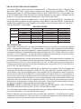
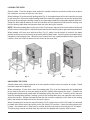
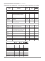
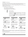
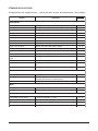
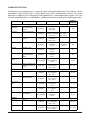
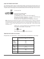
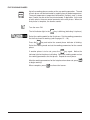
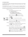
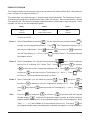
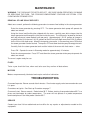
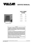
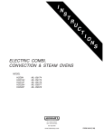
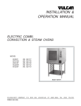
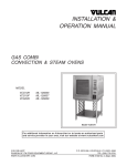
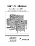
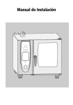
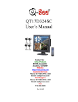
INSTALLATION &
OPERATION MANUAL
GAS COMBI OVENS
MODEL
VC10HGP
VC20HGP
VC10FGP
VC20FGP
ML-52441
ML-52442
ML-52444
ML-114799
MODEL VC10HGP
VULCAN-HART
COMPANY,
FORM 31010 Rev. B (7-99)
P.O.
BOX
696,
LOUISVILLE,
KY
40201-0696,
TEL. (502) 7 7 8 - 2 7 9 1
1
IMPORTANT FOR YOUR SAFETY
THIS MANUAL HAS BEEN PREPARED FOR PERSONNEL QUALIFIED TO INSTALL GAS
EQUIPMENT, WHO SHOULD PERFORM THE INITIAL FIELD START-UP AND
ADJUSTMENTS OF THE EQUIPMENT COVERED BY THIS MANUAL.
POST IN A PROMINENT LOCATION THE INSTRUCTIONS TO BE FOLLOWED IN THE
EVENT THE SMELL OF GAS IS DETECTED. THIS INFORMATION CAN BE OBTAINED
FROM THE LOCAL GAS SUPPLIER.
IMPORTANT
IN THE EVENT A GAS ODOR IS DETECTED, SHUT DOWN
UNITS AT MAIN SHUTOFF VALVE AND CONTACT THE
LOCAL GAS COMPANY OR GAS SUPPLIER FOR
SERVICE.
FOR YOUR SAFETY
DO NOT STORE OR USE GASOLINE OR OTHER
FLAMMABLE VAPORS OR LIQUIDS IN THE VICINITY OF
THIS OR ANY OTHER APPLIANCE.
WARNING: IMPROPER INSTALLATION, ADJUSTMENT,
ALTERATION, SERVICE OR MAINTENANCE CAN CAUSE
PROPERTY DAMAGE, INJURY OR DEATH. READ THE
INSTALLATION, OPERATING AND MAINTENANCE
INSTRUCTIONS THOROUGHLY BEFORE INSTALLING OR
SERVICING THIS EQUIPMENT.
IN THE EVENT OF A POWER FAILURE, DO NOT
ATTEMPT TO OPERATE THIS DEVICE.
2
Table of Contents
GENERAL . . . . . . . . . . . . . . . . . . . . . . . . . . . . . . . . . . . . . . . . . . . . . . . 4
INSTALLATION . . . . . . . . . . . . . . . . . . . . . . . . . . . . . . . . . . . . . . . . . . . 4
UNPACKING . . . . . . . . . . . . . . . . . . . . . . . . . . . . . . . . . . . . . . .
LOCATION . . . . . . . . . . . . . . . . . . . . . . . . . . . . . . . . . . . . . . . .
LEGS . . . . . . . . . . . . . . . . . . . . . . . . . . . . . . . . . . . . . . . . . . . . .
TABLE . . . . . . . . . . . . . . . . . . . . . . . . . . . . . . . . . . . . . . . . . . . .
CONDENSATE GUTTER . . . . . . . . . . . . . . . . . . . . . . . . . . . . .
LEVELING . . . . . . . . . . . . . . . . . . . . . . . . . . . . . . . . . . . . . . . . .
INSTALLATION CODES AND STANDARDS . . . . . . . . . . . . .
GAS CONNECTION . . . . . . . . . . . . . . . . . . . . . . . . . . . . . . . . .
VENT HOOD . . . . . . . . . . . . . . . . . . . . . . . . . . . . . . . . . . . . . . .
WATER REQUIREMENTS . . . . . . . . . . . . . . . . . . . . . . . . . . . .
PLUMBING CONNECTIONS . . . . . . . . . . . . . . . . . . . . . . . . . .
WATER CONNECTION . . . . . . . . . . . . . . . . . . . . . . . . . . . . . .
DRAIN CONNECTION . . . . . . . . . . . . . . . . . . . . . . . . . . . . . . .
ELECTRICAL CONNECTION . . . . . . . . . . . . . . . . . . . . . . . . .
START UP PROCEDURE . . . . . . . . . . . . . . . . . . . . . . . . . . . .
BEFORE FIRST USE . . . . . . . . . . . . . . . . . . . . . . . . . . . . . . . .
4
4
4
4
4
4
5
5
6
6
6
6
7
7
7
8
OPERATION . . . . . . . . . . . . . . . . . . . . . . . . . . . . . . . . . . . . . . . . . . . . . 8
DOOR OPENING AND CLOSING . . . . . . . . . . . . . . . . . . . . . . 8
GREASE FILTER . . . . . . . . . . . . . . . . . . . . . . . . . . . . . . . . . . . 8
LOADING THE OVEN . . . . . . . . . . . . . . . . . . . . . . . . . . . . . . . 9
UNLOADING THE OVEN . . . . . . . . . . . . . . . . . . . . . . . . . . . . . 9
PROGRAMMABLE CONTROLS . . . . . . . . . . . . . . . . . . . . . . 10
BAKING (CONVECTION BAKING - HOT AIR) . . . . . . . . . . . 12
CONVECTION BAKING APPLICATIONS . . . . . . . . . . . . . . . 13
STEAMING . . . . . . . . . . . . . . . . . . . . . . . . . . . . . . . . . . . . . . . 14
STEAMING APPLICATIONS . . . . . . . . . . . . . . . . . . . . . . . . . 15
COMBI (CONVECTION BAKING WITH STEAMING) . . . . . 16
COMBI APPLICATIONS. . . . . . . . . . . . . . . . . . . . . . . . . . . . . 17
USING THE TEMPERATURE PROBE . . . . . . . . . . . . . . . . . 18
TEMPERATURE PROBE APPLICATIONS . . . . . . . . . . . . . . 18
FIVE COOKING PHASES . . . . . . . . . . . . . . . . . . . . . . . . . . . 19
PROGRAMMING MEMORY . . . . . . . . . . . . . . . . . . . . . . . . . 20
EXAMPLE PROGRAM . . . . . . . . . . . . . . . . . . . . . . . . . . . . . . 21
RECALLING A PROGRAM FROM MEMORY . . . . . . . . . . . 22
MENU CARD . . . . . . . . . . . . . . . . . . . . . . . . . . . . . . . . . . . . . 23
COOK AND HOLD . . . . . . . . . . . . . . . . . . . . . . . . . . . . . . . . . 24
COOK AND HOLD APPLICATIONS . . . . . . . . . . . . . . . . . . . 25
CLEANING . . . . . . . . . . . . . . . . . . . . . . . . . . . . . . . . . . . . . . . 26
DAILY CLEANING . . . . . . . . . . . . . . . . . . . . . . . . . . . . . . . . . 26
COMPLETE CLEANING . . . . . . . . . . . . . . . . . . . . . . . . . . . . 26
MAINTENANCE . . . . . . . . . . . . . . . . . . . . . . . . . . . . . . . . . . . . . . . . . 28
REMOVAL OF LIME SCALE DEPOSITS . . . . . . . . . . . . . . . 28
FLUES . . . . . . . . . . . . . . . . . . . . . . . . . . . . . . . . . . . . . . . . . . . 28
MOTORS . . . . . . . . . . . . . . . . . . . . . . . . . . . . . . . . . . . . . . . . . 28
TROUBLESHOOTING . . . . . . . . . . . . . . . . . . . . . . . . . . . . . . . . . . . . 28
SERVICE . . . . . . . . . . . . . . . . . . . . . . . . . . . . . . . . . . . . . . . . . 28
3
Installation, Operation, and Care of
GAS COMBI STEAM & CONVECTION OVENS
KEEP THIS MANUAL FOR FUTURE USE
GENERAL
The Gas Combi Steam & Convection Ovens are single compartment ovens that provide steam and/
or convection heating. Various models can handle 10 or 20 shelves, Full or Half depth. A
Programmable control is provided on all size/depth combinations. The bold numbers and letters
explain the model-number conventions. An atmospheric steam generator can provide humidification
in the oven chamber.
The 10 level models can be installed on an optional table or on a suitable countertop using the legs,
provided. Trolleys or landing tables (depending on size of oven) can load or unload all racks in one
easy motion. The hose spray accessory can be installed near the oven to facilitate easy cleaning.
INSTALLATION
UNPACKING
Immediately after unpacking the oven, check for possible shipping damage. If the oven is found to be
damaged, save the packaging material and contact the carrier within 15 days of delivery.
Prior to installation, verify that the electrical service and type of gas (natural or propane) agree with the
specifications on the oven data plate.
LOCATION
Allow space for operating the oven. Do not obstruct the ventilation ports above the oven. Do not install
the oven next to a major heat source, such as a griddle or fryer. All models require a minimum clearance
of 8" on the right side of the oven and 6" at the rear. The 8" clearance on the right side also provides
room for the gas connection. Additionally, model VC10FGP requires an 8" clearance on the left side.
LEGS (Provided for 10 Shelf Models)
To Drain
Screw feet into legs at four corners and set oven on suitable countertop.
Oven
Tube
TABLE (Optional for 10 Shelf Models)
To assemble the oven onto the caster equipped table, insert four bolts from
underneath at the four corners and tighten until secure.
CONDENSATE GUTTER
Condensate Gutter
Loosen screws under front of oven base and assemble condensate gutter to
bottom of oven. The 20 level ovens have a three segment condensate gutter and
dual input drain tube. Connect tube (if provided) to condensate gutter and drain.
Door
NOTE: The 20 level gas ovens are equipped with casters, preassembled on the bottom of the oven.
LEVELING
The oven must be placed in a level location. Using a spirit level or pan of water in the bottom of the
oven, make sure the oven is level, both front-to-back and side-to-side. After the drain is connected
(page 7), check for level by pouring water onto the floor of the compartment. All water should drain
through the drain opening.
4
INSTALLATION CODES AND STANDARDS
In the United States, install the oven in accordance with: 1) State and local codes; 2) National Fuel
Gas Code, ANSI-Z223.1, latest edition, available from American Gas Association, 1515 Wilson
Boulevard, Arlington, VA 22209; 3) National Electrical Code, ANSI/NFPA No. 70, latest edition; and
4) NFPA Standard #96, Vapor Removal from Cooking Equipment, latest edition, available from the
National Fire Protection Association, Batterymarch Park, Quincy, MA 02269.
In Canada, install the oven in accordance with: 1) Local codes; 2) CAN/CGA-B149.1, Installation for
Natural Gas Burning Appliances and Equipment, latest edition; 3) CAN/CGA-B149.2, Installation for
Propane Burning Appliances and Equipment, latest edition; and, 4) Canadian Electrical Code, Part 1,
CSA Standard C22.1, latest edition.
GAS INPUT RATING
Model
VC10HGP
VC10FGP
VC20HGP
VC20FGP
Gas Type
Oven
Steam Generator
Total
Natural
Propane
Natural
Propane
Natural
Propane
Natural
Propane
67,000 BTU/hr
69,000 BTU/hr
85,000 BTU/hr
85,000 BTU/hr
70,000 BTU/hr
70,000 BTU/hr
150,000 BTU/hr
150,000 BTU/hr
40,000 BTU/hr
40,000 BTU/hr
45,000 BTU/hr
45,000 BTU/hr
58,000 BTU/hr
58,000 BTU/hr
115,000 BTU/hr
115,000 BTU/hr
107,000 BTU/hr
109,000 BTU/hr
130,000 BTU/hr
130,000 BTU/hr
128,000 BTU/hr
128,000 BTU/hr
265,000 BTU/hr
265,000 BTU/hr
GAS CONNECTION
All gas supply connections and any pipe joint compound must be resistant to the action of propane
gases. The machine connection is 3/4" external thread. A manual valve (supplied) must be installed
in the gas supply line ahead of the appliance. Make sure piping is clean and free of obstructions, dirt,
or pipe joint compound. Recommended gas supply pressures are 7" W.C. (Water Column) for natural
gas and 11" W.C. for propane. The gas line must be capable of delivering gas to the oven without
excessive pressure drop at the rate specified on the rating plate.
The oven is equipped with a factory preset pressure regulator. Natural gas pressure regulators are
preset for 3.5" W.C. for both ovens and steam generators. Propane gas pressure regulators for 10 level
half and full and 20 level full ovens are preset for 10" W.C. for both ovens and steam generators.
Propane gas pressure regulators for 20 level half depth ovens are preset for 8" W.C. for oven burners
and 10" W.C. for steam generators.
Caster equipped ovens must be installed with a connector that complies with the Standard for
Connectors for Movable Gas Appliances, ANSI-Z21.69 (latest edition) [in Canada, CAN/CGA-6.16,
latest edition], and a quick-disconnect device that complies with the Standard for Quick-Disconnect
Devices for Use with Gas Fuel, ANSI-Z21.41 (latest edition) [in Canada, CAN 1-6.9, latest edition]. A
gas line strain relief must be provided to limit the movement of the oven without depending on the
connector and the quick-disconnect device or its associated piping to limit oven movement. Attach the
strain relief to the rear of the oven at the location provided. If it is necessary to disconnect the restraint
during service or maintenance, first turn off the gas supply. Reconnect the restraint before returning
the oven to its original installed location and turning the gas supply on.
WARNING: PRIOR TO LIGHTING, CHECK ALL JOINTS IN THE GAS SUPPLY LINE FOR LEAKS.
USE SOAP AND WATER SOLUTION. DO NOT USE AN OPEN FLAME.
The convection burner and the steam generator burner are ignited automatically by electric igniters;
there are no pilot lights. See Start Up Procedure, page 7.
Keep the appliance area free and clear from all combustible substances. Do not obstruct the flow of
combustion and ventilation air. Make sure there is an adequate supply of air in the room to allow for
combustion at the burners and exhaust by the vent hood system.
5
Testing the Gas Supply Piping System
When test pressures exceed 1/2 psig (3.45 kPa), the oven and its individual shutoff valve must be
disconnected from the gas supply piping system.
When test pressures are 1/2 psig (3.45 kPa) or less, the oven must be isolated from the gas supply
piping system by closing its individual shutoff valve.
VENT HOOD
The Combi oven should be located under a suitable exhaust hood to vent steam, smoke, grease laden
vapors, etc. Information on the construction and installation of ventilating hoods may be obtained from
Vapor Removal from Cooking Equipment, NFPA standard No. 96 (latest edition).
WATER REQUIREMENTS
Proper water quality can improve the taste of the food prepared in the oven, reduce liming in the steam
generator, and extend equipment life. Local water conditions vary from one location to another. The
recommended proper water treatment for effective and efficient use of this equipment will also vary
depending on the local water conditions. Ask your municipal water supplier for details about your local
water supply prior to installation.
Recommended water hardness is 2.0 to 4.0 grains of hardness per gallon with pH from 7.0 to 8.0.
Chlorides must not exceed 30 parts per million. Water hardness above 4.0 grains per gallon should
be treated by a water conditioner (water softener or in-line water treatment). Water hardness below
2.0 grains per gallon may also require a water treatment system to reduce potential corrosion. With
respect to water hardness, 17.1 parts per million is equal to 1 grain of hardness per gallon. Water
treatment has been shown to reduce costs associated with machine cleaning, reduce deliming of the
steam generator, and reduce corrosion of metallic surfaces in the steam generator.
Water supplies vary from one location to another. A local water treatment specialist should be
consulted before installing any steam generating equipment.
The Kleensteam® system by Everpure is an available Vulcan accessory. The Kleensteam system is
a passive chemical feeder that modifies the water supply by addition of a non-toxic chemical which
increases the acidity of water, reducing the alkalinity. This generally allows the steam generator to run
cleaner and require less frequent deliming. Kleensteam reduces the chemical taste and odor of
chlorine and filters out small particulates. The cartridge needs to be replaced every six months.
Sediment, silica, excess chlorides, or other dissolved solids may lead to a recommendation for
alternate form(s) of water treatment. Consult with a water treatment specialist and your Vulcan Sales
office for specific recommendations.
PLUMBING CONNECTIONS
WARNING: PLUMBING CONNECTIONS MUST COMPLY WITH APPLICABLE SANITARY, SAFETY
AND PLUMBING CODES.
WATER CONNECTION
Connect the potable water supply to the external-threaded nylon inlet (3/4" NSHT - National Straight
Hose Thread) located underneath the oven at the rear. Treat the nylon threads carefully so the
connection does not leak. A manual shutoff valve must be provided convenient to the oven; this valve
should be open when the oven is in operation. Water pressure should be between 20 and 80 psig.
Untreated water contains scale producing minerals which can precipitate onto the surfaces in the
steam generator tank. Due to the temperatures in the tank, the minerals can bake onto the surfaces
and components. This can result in early component failure and reduced product life.
Sensors in the steam generator tank use ions in the water to detect the water level. Do not use distilled
(fully demineralized or de-ionized) water as this could provide a false reading to the sensors.
6
Strainers and filters will NOT remove minerals from the water.
Refer to REMOVAL OF LIME SCALE DEPOSITS, page 28.
DRAIN CONNECTION
CAUTION: In order to avoid any back pressure in the oven, do not connect solidly to any drain
connection.
An adaptor collar is recommended for the machine drain connection, located underneath the oven at
the rear. The drain line should be plumbed to an open gap-type drain and include a trap. Drain piping
must have suitable pitch, have appropriate support along its length, and have no connection to other
piping. The material used in the drain line should be heat resistant to at least 212°F. The open drain
should be located between 3 and 5 feet away from the perimeter of the oven to reduce potential damage
from moisture-corrosion.
ELECTRICAL CONNECTION
Cord Connected Ovens
WARNING: THE SUPPLY CORD ON THIS OVEN IS PROVIDED WITH A GROUNDING PLUG. THE
OUTLET TO WHICH THIS PLUG IS CONNECTED MUST BE PROPERLY GROUNDED. IF THE
RECEPTACLE IS NOT THE PROPER GROUNDING TYPE, CONTACT AN ELECTRICIAN.
The wiring diagram is located on the inside surface of the right side panel as you face the oven.
START UP PROCEDURE
The Gas Combi Ovens are equipped with a gas burner for convection heating and a gas steam
generator for atmospheric steaming; two independent flues exhaust the burnt gases. Become familiar
with the entire manual before continuing with this Startup Procedure. Remove the tray rack, grease
filter, and fan baffle from the oven cavity. Turn gas and water on. Press the ON button.
• Select Combi Mode and adjust the steam time to 50% by pressing
four times (four
indicator lights are lit).
• Leave oven temp setting at 302°F and the timer display blank, [-]h [--]min.
• Close the oven door and press the Start Button. The oven convection fan rotates counterclockwise.
The oven flue vent should be open.
• After a delay of 50 seconds while the oven adjusts for Combi Mode, the sparker on the left side of
the burner should ignite the Convection Burner. Observe blue flame. After an additional 70 seconds,
the steam generator flame should ignite. Observe blue flame through window below controls.
, will be lit.
If the Convection Burner does not ignite, the NO Convection Burner indicator light,
• Wait 30 seconds until the
light starts to flash and the buzzer sounds.
indicator light.
• Reset the Convection Burner by pressing the Reset Button above the
• This procedure may need to be repeated several times until all of the air in the pipeline is replaced
by gas. The longer the pipe, the longer it will take to remove the air from the pipe.
, will be lit.
If the Steam Generator Burner does not ignite, the NO Steam Burner indicator light,
• Wait 10 seconds until the
light starts to flash and the buzzer sounds.
• Reset the Steam Generator Burner by pressing the Reset Button above the
indicator light.
• This procedure may need to be repeated several times until all of the air in the pipeline is replaced
by gas.
If a make-up air system is part of the vent hood, make sure there is no down-draft pushing hot
combustion gases from the flues back into the oven.
Press Stop and observe that the pump drains the steam generator for about one minute. The door will
open. After the oven is cool, reinstall fan baffle, grease filter, and tray rack.
7
BEFORE FIRST USE
Before using the oven for the first time, it must be "burned in" to release any odors that might result from
heating the new surfaces in the oven. Operate the oven at 480°F for 45 minutes in Convection Mode.
OPERATION
WARNING: THE OVEN AND ITS PARTS ARE HOT. USE CARE WHEN OPERATING, CLEANING
OR SERVICING THE OVEN. THE COOKING COMPARTMENT CONTAINS LIVE STEAM. STAY
CLEAR WHEN OPENING DOOR.
DOOR OPENING AND CLOSING
The oven door is equipped with an electrically powered lock. The oven is delivered with the door
latched and slightly open (Fig. 1) and can be opened by firmly pulling the door handle (Fig. 3). Push
the door until it connects with the latch but remains slightly open (Fig. 1). This is the position the door
should be in when the oven is not in use. The door should also be in this position after cooking to allow
steam to escape before fully opening the door. Push the handle until it is in line with the oven door.
If power has been connected, the door will now lock automatically, sealing the oven chamber (Fig. 2).
To release the door, rotate (pull) the handle 90 degrees. The door automatically releases to the
'latched and slightly opened' position. Allow a few seconds for steam to escape before pulling the door
open (Fig. 3).
→
Fig. 1
Fig. 2
Fig. 3
NOTE: In the event of a power failure, the door may be opened by pulling the handle firmly towards
you while firmly pressing against the front of the oven with the other hand.
GREASE FILTER
The grease filter in the rear of the oven chamber should be kept in place. See Cleaning, page 26, for
information on how to remove the grease filter and how to reinstall it.
8
LOADING THE OVEN
Open the door. Place the product to be cooked in suitable containers and slide into the racks or place
the containers securely on shelves in the oven.
When loading a 10 level oven with landing table (Fig. 4), the bottom frame of the rack should be secured
by the rotary lock. Move the loaded landing table to the front of the open oven; secure the landing table
to the oven by actuating the locking-clamp (or use your body to hold the landing table against the oven).
Rotate the lock-knob to release the rack and carefully roll the loaded rack into the oven, making sure
that the landing table does not separate from the oven during the transfer.
NOTE: When the landing table is not in use in the 10 level oven, make sure the insert retainer (delivered
with the oven) is fitted under the fan baffle to prevent the rack from tilting when pans are being removed.
When loading a 20 level oven with the trolley (Fig. 5), make sure the handle is locked in the down
position so the rack is held securely to the trolley with its lifting hooks. Carefully move the loaded trolley
completely into the open oven. When the rear frame of the rack is positioned behind the edge of the
retainer, raise the handle to lower the rack-frame to the oven floor.
Fig. 4
Fig. 5
UNLOADING THE OVEN
Allow the door to be 'slightly-opened' for a few seconds to allow hot air and steam to escape. Stand
behind the door while opening.
When unloading a 10 level oven, move the landing table (Fig. 4) so the clamp locks the landing table
to the front of the oven (or use your body to hold the landing table against the oven). Remove the
landing table handles and clamp them to the bottom of the hot oven rack. Carefully roll the hot rack
onto the landing table platform, making sure that the landing table does not separate from the oven
during the transfer. Rotate the knob to allow the rack to move completely to the front of the landing
table; and rotate the knob back to lock the rack in place.
When unloading a 20 level oven, move the trolley (Fig. 5) into the oven until the "lift-hooks" are inserted
into both sides of the front frame of the rack in the correct "lift" position. Lower the trolley handle until
it stops; the loaded-rack is lifted from its retainer and held securely to the trolley by the "lift-hooks".
The trolley may now be removed from the oven with the loaded rack securely held in place.
9
PROGRAMMABLE CONTROLS
OFF
ON
HOT AIR
STEAM
Main Power: On / Off
Mode Selection:
Hot Air
Steam
COMBI
Start / Stop
Combi
Phase 1 – 5
Select & Set:
h
min
Cooking Time
TIME
DOWN
UP
Probe Temperature
PROBE
Select & Set:
Oven Temp
Temperature Differential
T
TEMP
DOWN
UP
Select Program Number
ENTER
DOWN
RESET
10
RESET
UP
Service Needed: Air Intake Filter
Reset: Convection Burner Ignition
Reset: Steam Generator Burner Ignition
Service Needed: Oven Fan
The water supply valve must be open before starting Steam or Combi operations (refer to Start Up
Procedure, page 7). If there is not enough water in the steam generator, the buzzer will sound for one
minute and then the two lights on the steam button and the phase lights will start flashing.
Main Power: On / Off
ON
— Main power is on and the ON indicator light is lit. The actual oven temperature is
shown in the Temperature display; – h – – min is in the Time display. The control
will now accept other commands.
OFF
— Shuts off the oven at the end of the day, opens the oven vent, and drains the steam
generator tank (pump requires about one minute to drain the tank).
Mode Selection: Hot Air / Steam / Combi / Start Stop / Phase 1 – 5
HOT AIR — Heat and Fan are ON. The initial temperature setting of 302°F displays, then the
actual oven temperature displays. Use TEMP and the UP or DOWN keys to set the
temperature (range is 35 – 518°F). The bottom green indicator light is lit when the
convection burner is on.
STEAM — Steam and Fan are ON. The initial temperature setting of 212°F displays, then the
actual oven temperature displays. Use TEMP and the UP or DOWN keys to set the
temperature (range is 35 – 212°F). The bottom green indicator light is lit when the
steam generator burner is on.
COMBI — Heat, Fan, and Steam are ON. Initial temperature setting of 302°F displays, then the
actual oven temperature displays. Use TEMP and the UP or DOWN keys to set the
temperature (range is 35 – 518°F). The amount of steaming is determined by the
number of times you press the Combi key (1 – 6), indicated by the row of lights.
START STOP — Starts or stops the cooking operation.
PHASE — Indicates the Phase of a sequential cooking operation. Up to 5 phases are permitted.
Select & Set: Cooking Time or Probe Temperature / Down / Up
DISPLAY — Allows the Cooking Time or the Probe Temperature to be set.
TIME
— Selects the Cooking Time, which can be increased or decreased using the Up or
Down keys. If the display shows [-]h[--]min, the oven operates continuously — there
is no automatic shut-off.
DOWN — Decreases the Cooking Time or Probe Temperature.
UP
— Increases the Cooking Time or Probe Temperature.
PROBE — Selects the Probe Temperature, which can be increased or decreased using the time
Up or Down keys.
Temperature Display: Oven Temp / Down / Up / Temperature Differential
Oven Temp — Changes the display from the Actual Oven Temperature to the Oven Temperature
Setting, which can be increased or decreased using the Up or Down keys.
DOWN
— Decreases the Oven Temperature or Temperature Differential setting.
UP
— Increases the Oven Temperature or Temperature Differential setting.
Temp Diff — Used with the temperature probe to maintain the temperature differential between
the meat probe and the oven — as the product is heated, the oven temperature
increases, maintaining the differential.
Program Number Display: Prog. / Down / Up / Enter
PROG.
DOWN
UP
ENTER
—
—
—
—
Accesses memory to allow programming. Initially displays Program 1 (range: 1 – 99).
Decreases the Program Number.
Increases the Program Number.
Saves the entered cooking program (up to 5 Phases) under the Program Number.
Programs that are properly saved will not be lost during a power outage or
disconnection.
11
BAKING (Convection Baking – HOT AIR)
Convection Baking involves baking, browning, roasting, etc. without adding steam or moisture to the
process. The hot air is fan-circulated to maintain even temperatures throughout the oven.
Automatic Convection Baking can be set up using either the elapsed Cooking Time or the internal
Probe Temperature to set off the buzzer.
Three combinations of oven settings can be set . . .
•
Oven Temperature and Cooking Time.
•
Oven Temperature and Probe Temperature.
•
Temperature Differential and Probe Temperature.
Turn the oven ON.
Select Convection (HOT
AIR)
Mode.
Preheat the oven before loading product. Press
and set the Oven
Temp (35 – 518°F). Use the Up or Down arrows to increase or decrease.
Leave the time setting blank [ -h -- min ]. Press
temperature to reach the temperature setting.
and wait for the oven
• Oven Temp and Cook Time
• Oven Temp and Probe Temp
• Temp Diff and Probe Temp
and set the Oven
Press
Temp.
Use the Up or Down arrows to
increase or decrease.
Press
and set the Oven
Temp.
Use the Up or Down arrows to
increase or decrease.
T
Press
and set the
Temperature Differential (110°F
recommended for Hot Air mode).
Use the Up or Down arrows to
increase or decrease.
Press
and set the Cooking
Time. Use the Up or Down
arrows to increase or decrease.
Press
and set the Probe
Temp. Use the Up or Down
arrows to increase or decrease.
Load the oven and close the
door.
Load the oven. Insert the probe
near the center of the product.
Close the door.
Press
to begin.
Press
When complete, press
silence the buzzer.
and set the Probe
Press
Temp. Use the Up or Down
arrows to increase or decrease.
Load the oven. Insert the probe
near the center of the product.
Close the door.
to begin.
to
Press
When complete, press
silence the buzzer.
to begin.
to
When complete, press
silence the buzzer.
to
NOTES:
The minimum temperature for the probe to function is 35°F — if product is below 35°, set the probe temperature
before inserting the probe in the product. If the product is below 35°F, the initial cooking phase must not be
terminated by probe temperature. During Operator training to demonstrate use of the probe, place the probe
in a container of water to simulate cooking of actual product.
If you select probe temperature or temperature differential and want to switch back to conventional operation,
press
12
.
CONVECTION BAKING APPLICATIONS – HOT AIR MODE
All Applications are suggested only — prove your own recipes and temperature / time settings.
Product
Preparation
Preheat Temp
(OF)
Oven Temp
(OF)
Time
(minutes)
FISH
Cod or Mullet, fresh
Season, Oil
390
350
10 - 12
Sea-frozen fish fillet
Thoroughly oil plate bottom and upper side
of fish fillet. After baking, let stand for 2
minutes to avoid sticking and make
portioning easier.
480
350
10 - 12
Sole, fresh
Season, Oil
425
350
10 - 12
Trout, fresh
Season, Oil
425
350
10 - 12
Trout, frozen
Season, Oil
425
350
15 - 22
Trout, breaded, fresh
Dip in flour, egg, breadcrumb mixture
Grease pan thoroughly
480
435
15 - 20
Pork Chop, fresh,
sauteed
Season, Oil lightly
480
350
10 - 12
Pork Chop, frozen,
sauteed
Oil lightly; Season after roasting
480
425
15
Pork Cutlet, fresh
4 - 5 oz
Dip in egg, breadcrumb batter, thoroughly
oil the breaded surface of the cutlets, avoid
leaving dry spots, lightly oil plate bottom.
480
425
10 - 12
Pork Cutlet, fresh,
breaded
Oil both sides
425
350
10 - 12
Pork Loin Cutlet, fresh Do not season
4 - 5 oz
480
425
6-8
Ham Steak, fresh
Season, Oil lightly
480
350
6 - 10
Pork Sausage, fresh
Oil lightly
480
425
8 - 10
Pork Steak, fresh
Season, Oil lightly
500
480
7
Pork Steak, frozen
Oil, Season after roasting process
500
425
10 - 12
PORK
Product
Preheat Temp
(OF)
Oven Temp
(OF)
Time
(minutes)
PASTRY
Puff Pastry
340
340
18 - 20
Danish Pastry
350
350
18 - 20
340 - 350
340 - 350
16 - 18
Cake
350
350
8
Fruit Cake
320
320
55 - 65
Yeast Rolls with milk
390
390
10 - 12
Almond Pastry
350
350
10 - 12
Nut Pastry
350
350
10 - 12
Chocolate Pastry
350
350
10 - 12
Biscuit Pastry
350
350
10 - 12
Flaky Pastry
13
STEAMING (Steam Mode only)
Steam cooking is used for stewing, poaching, and gentle cooking of products cooked in water. Steam
flows without pressure into the oven. The fan circulates the steam to all parts of the oven.
Automatic Steaming can be set up using either the elapsed Cooking Time or the internal Probe
Temperature to set off the buzzer.
Three combinations of oven settings can be set . . .
•
Oven Temperature and Cooking Time.
•
Oven Temperature and Probe Temperature.
•
Temperature Differential and Probe Temperature.
Turn the oven ON.
Select Steam Mode.
If starting from cold, preheat the steam generator for 6 - 8 minutes before
and set the Oven Temp (35 – 212°F). Use the
loading product. Press
Up or Down arrows to increase or decrease. Leave the time setting blank
[ -h -- min ]. Press
temperature setting.
and wait for the oven temperature to reach the
• Oven Temp and Cook Time
• Oven Temp and Probe Temp
• Temp Diff and Probe Temp
Press
and set the Oven
Temp.
Use the Up or Down arrows to
increase or decrease.
Press
and set the Oven
Temp.
Use the Up or Down arrows to
increase or decrease.
T
Press
and set the
Temperature Differential (60°F
recommended for Steam mode).
Use the Up or Down arrows to
increase or decrease.
and set the Cooking
Press
Time. Use the Up or Down
arrows to increase or decrease.
Press
and set the Probe
Temp. Use the Up or Down
arrows to increase or decrease.
Load the oven and close the
door.
Load the oven. Insert the probe
near the center of the product.
Close the door.
Press
to begin.
Press
When complete, press
silence the buzzer.
Press
and set the Probe
Temp. Use the Up or Down
arrows to increase or decrease.
Load the oven. Insert the probe
near the center of the product.
Close the door.
to begin.
to
Press
When complete, press
silence the buzzer.
to begin.
to
When complete, press
silence the buzzer.
to
NOTES:
The minimum temperature for the probe to function is 35°F — if product is below 35°, set the probe temperature
before inserting the probe in the product. If the product is below 35°F, the initial cooking phase must not be
terminated by probe temperature.
If you select probe temperature or temperature differential and want to switch back to conventional operation,
press
14
.
STEAMING APPLICATIONS
All Applications are suggested only — prove your own recipes and temperature / time settings.
Product
Preparation
Time
(minutes)
VEGETABLES
Asparagus, fresh
Sprinkle with lemon drops before cooking
12 - 15
Broccoli, fresh
Season after cooking
15 - 18
Brussels Sprouts, fresh or frozen
Season after cooking
15 - 18
Cabbage, white, sliced, fresh
Carrots, small, fresh or frozen
15 - 18
Season after cooking
Carrots, diced, fresh
18 - 20
15 - 18
Cauliflower, fresh or frozen
Season after cooking
15 - 18
Cauliflower, head, fresh
Sprinkle with lemon drops before cooking
18 - 20
Celery, slices or diced
Sprinkle with lemon drops before cooking
18 - 20
Corn, on-the-cob, fresh
Sprinkle with lemon drops before cooking
15 - 18
Eggplant
10
Green Beans, fresh or frozen
Season after cooking
18 - 20
Mushrooms, halved, quartered, or
sliced
Sprinkle with lemon drops before cooking
8 - 10
Peas, frozen
Season after cooking
12 - 15
Potatoes
Soak in 10% salt water for 15 minutes before cooking; or, salt
dry
30 - 35
Spinach, fresh
2-4
SIDE DISHES
Dumplings, Meat Balls
Steam without added water
15 - 20
Pasta
Before cooking, cover with hot water and add some oil. Mix
thoroughly once during the cooking process.
20 - 25
Rice
Add water to 150% of rice depth.
20 - 25
Brisket
Add seasoning and vegetables to the meat
90 - 120
Veal, fricassee
Add seasoning and vegetables to the meat
45 - 50
Cod, Halibut, fresh or frozen
In serving size portions, 12 / pan
10 - 12
Crayfish Tails, frozen
Sprinkle with lemon drops and perhaps cover with fresh dill
12 - 15
Mussels
Add some wine
8 - 10
Salmon, fresh
Season with lemon
8 - 10
MEAT
FISH & CRUSTACEANS
15
COMBI (Convection Baking with Steaming)
Combi Baking and Steaming is used for baking, roasting, or braising when steam needs to be added
to the oven during a convection baking operation. The 'Percent Steam Time' can be varied by
repeatedly pressing the Combi key — see % Steam Time in the table below.
Automatic Combi Baking and Steaming can be set up using either the elapsed Cooking Time or the
internal Probe Temperature to set off the buzzer.
Three combinations of oven settings can be set . . .
•
Oven Temperature and Cooking Time.
•
Oven Temperature and Probe Temperature.
•
Temperature Differential and Probe Temperature.
Turn the oven ON.
Indicator
Lights
•
••
•••
••••
•••••
••••••
% Steam Time
Press once.
20%
Press twice.
30%
Seconds Seconds
ON
OFF
16
64
24
56
Press three times.
40%
32
48
Press four times.
50%
40
40
Press five times.
60%
48
32
Press six times.
75%
60
20
Select Combi Mode and set % Steam Time.
If starting from cold, preheat the steam generator for 10 minutes at 75%
Steam Time (six indicator lights in Combi Mode) before loading product.
and set the Oven Temp (35 – 518°F). Use the Up or Down
Press
arrows to increase or decrease. Leave the time setting blank [ -h -- min].
Press
and wait 10 minutes.
• Oven Temp and Cook Time
• Oven Temp and Probe Temp
• Temp Diff and Probe Temp
Press
and set the Oven
Temp.
Use the Up or Down arrows to
increase or decrease.
and set the Oven
Press
Temp.
Use the Up or Down arrows to
increase or decrease.
T
and set the
Press
Temperature Differential (110°F
recommended for Combi mode).
Use the Up or Down arrows to
increase or decrease.
and set the Cooking
Press
Time. Use the Up or Down
arrows to increase or decrease.
Press
and set the Probe
Temp. Use the Up or Down
arrows to increase or decrease.
Load the oven and close the
door.
Load the oven. Insert the probe
near the center of the product.
Close the door.
Press
to begin.
Press
When complete, press
silence the buzzer.
NOTES:
Press
and set the Probe
Temp. Use the Up or Down
arrows to increase or decrease.
Load the oven. Insert the probe
near the center of the product.
Close the door.
to begin.
to
Press
When complete, press
silence the buzzer.
to begin.
to
When complete, press
silence the buzzer.
to
The minimum temperature for the probe to function is 35°F — if product is below 35°, set the probe temperature
before inserting the probe in the product. If the product is below 35°F, the initial cooking phase must not be
terminated by probe temperature.
If you select probe temperature or temperature differential and want to switch back to conventional operation,
press
16
.
COMBI APPLICATIONS
All Applications are suggested only — prove your own recipes and temperature / time settings. Combi
applications typically begin with a Steam Mode phase which automatically preheats the steam
generator in readiness for a subsequent Combi Mode phase. Some applications contain a HOT AIR
or Convection Mode phase. Combi Mode is seldom performed as a single phase cooking operation.
Preparation
Phase 1
Phase 2
Phase 3
Total Time
(minutes)
Boned & Rolled
Roast Beef
Season, oil, add carrots,
leaks, onions, and
red wine
Steam
90 minutes
Combi
60 minutes
250 - 280 °F
–
150
Roast Beef
Season and oil lightly
Steam
20 minutes
Combi
15 minutes per pound
280 - 320 °F
Convection
10 minutes
360 - 390 °F
—
Steam
30 minutes
Combi
40 minutes
280 - 320 °F
–
70
Steam
90 minutes
Combi
55 minutes
320 °F
Convection
10 minutes
390 °F
155
Steam
10 minutes
Combi
55 minutes
350 °F
–
65
Steam
45 minutes
Combi
20 minutes
350 °F
–
65
Steam
15 - 20 minutes
Combi
60 - 70 minutes
290 °F
–
75 - 90
Steam
20 minutes
Combi
70 - 80 minutes
280 - 320 °F
–
90 - 100
Steam
10 minutes
Combi
30 - 40 minutes
280 - 320 °F
–
40 - 50
Steam
10 minutes
Combi
60 - 70 minutes
250 - 280 °F
–
70 - 80
Steam
5 - 6 minutes
Combi
5 - 6 minutes
350 °F
–
10 - 12
Steam
5 minutes
Combi
5 - 7 minutes
390 °F
–
10 - 12
Steam
40 - 45 minutes
Combi
15 minutes
340 °F
–
55 - 60
Steam
10 minutes
Combi
90 - 100 minutes
280 - 320 °F
–
100 - 110
Steam
10 minutes
Combi
100 - 110 minutes
280 - 320 °F
–
110 - 120
Product
BEEF
Roulades
Season, oil, and add
red wine
Braised Beef
Meat Loaf
Stuffed Cabbage
Oil lightly in pan
Season, sprinkle with
caraway and brown
onions
Veal, Brisket,
stuffed
Season, oil lightly
Veal, Roast Loin of
Season, oil lightly, add
vegetables as basis of
sauce
PORK
Pork Loin, Boneless Add red wine
Pork Pie or Meatloaf Approximately 4 - 5 lb
per aluminum pan
Pork Sausage,
coarse
Pork Sausage, fine
Stuffed Peppers
Place with the opening
on the bottom
POULTRY
Chicken
Turkey or Goose
Season
Season
17
USING THE TEMPERATURE PROBE
The Temperature Probe is kept in a metal bracket (holder) at the top of the oven when not in use.
Remove the probe from its holder; the cable remains permanently connected to the top of the oven.
The probe cable is long enough to allow the product to be placed on one of the upper racks in the oven.
Turn the oven ON.
Select one of the cooking modes:
Convection, Steam, or Combi.
In Combi Mode, set the % Steam Time (refer to page 16).
Select and set the Probe Temperature. The oven will automatically shut
itself off when the Probe Temperature is reached.
Set either the Oven Temperature or the Temperature Differential.
NOTE: Setting the Oven Temperature will maintain a constant temperature in the oven. Setting the Temperature
Differential will gradually increase the temperature in the oven as the internal temperature of the product increases.
The control maintains the differential or difference between the Oven Temperature and the Probe Temperature. Refer
to pages 12, 14, and 16 when setting temperatures for the various cooking modes. Observe minimum Probe
Temperature of 35°F.
Load the oven. Insert the probe so its tip is approximately in the middle
of the product to be cooked. Close the door.
Press
to begin.
When complete, press
to silence the buzzer.
TEMPERATURE PROBE APPLICATIONS
All Applications are suggested only — prove your own recipes and temperature / time settings.
Recommended Final Probe Temperatures
°F
Beef
Rare
Medium
Well Done
18
140
160
170
Lamb
175 – 185
Pork
Fresh
Smoked
170
140 – 170
Turkey
Whole
Boneless
185
170
Veal
170
FIVE COOKING PHASES
Up to five cooking phases can be set for any cooking operation. The end
of each phase can be terminated by cooking time or probe temperature.
The oven temperature, temperature differential (if probe), and % steam
time (Combi) can be set for the selected mode, if applicable. At the end
of each phase, the oven control proceeds to the next phase. When the
final phase is complete, the buzzer sounds.
Turn the oven ON.
The left indicator light in the
key is blinking (indicating 1st phase).
Select the cooking mode for the first phase. Set the cooking parameters
for the first phase of cooking (refer to pages 12 – 18).
Press the
key and notice the second phase indicator is blinking.
Select the cooking mode and set the cooking parameters for the second
phase.
If another phase is to be set, press the
key again. Notice the
indicator light for that phase is blinking. Select the cooking mode and set
the cooking parameters for that phase. Repeat for each phase.
After the cooking parameters for the last phase have been set, press
to begin cooking.
When complete, press
to silence the buzzer.
19
PROGRAMMING MEMORY
The Programmable Control allows up to 99 Cooking Programs with up to 5 Phases in each program
to be keyed-in and stored in Memory. Each program is accessed by its identifying number. Program
numbers range from 1 – 99.
If the numbered Program has not been programmed (or is vacant), the Temperature displays the
current temperature, the Time displays – h – – min, and no Mode or Phase indicator lights are lit.
If the Program has already been programmed, its values are recalled from memory and displayed. You
can view all the programmed information by stepping through the phases using the phase button.
To CREATE a new program —
Select the cooking mode: Hot Air, Steam, or Combi.
If Combi, set % Steam Time.
Set the oven settings desired . . .
• Oven Temperature and Cooking Time.
• Oven Temperature and Probe Temperature.
• Temperature Differential and Probe Temperature.
End of the 1st Phase. Press
to shift to the next phase.
Repeat the above for as many of the 5 phases as are needed.
Press
Press the
twice.
key. The program number is displayed.
Use Up or Down arrows to increase or decrease until a vacant program
until the program number stops being
number is found. Then press
displayed and the program is saved in memory.
To DELETE an existing program — Find the program number.
Press
and hold it in for about 3 seconds until the program number
stops flashing, indicating the program has been deleted.
To CHANGE an existing program — Find the program number.
Key in any temperature or time changes for each phase; press
to
shift to the next phase. The phase key allows all program information to
be displayed. The flashing program number indicates that one or more
changes have been made to the program. Press
twice. Then press
and hold it in for about 3 seconds until the program number stops
flashing, indicating the changed program has been saved.
20
EXAMPLE PROGRAM
This example shows how to program a three-phase process for cooking Roast Beef, 18 pounds per
roast, and store it as program number 20.
The second item in the table on page 17 provides most of the information: For Combi time, Phase 2,
15 minutes-per-pound times 18 pounds-per-roast yields 270 minutes. We assumed that 20% Steam
Time would be OK. We chose the average temperature when a temperature range was given. In this
example, we will not use the temperature probe.
Phase 1
Phase 2
Phase 3
STEAM Mode
212 °F
20 minutes
COMBI Mode - 20% Steam Time
295 °F
4 hours and 30 minutes
CONVECTION (HOT AIR Mode)
375 °F
10 minutes
Turn the oven ON.
Phase 1
Select Steam Mode by pressing
. The first light blinks on the phase button
: The Temperature displays 212°F
indicate you are programming Phase 1. Press
and needs no adjustment. Press
and press
until the Time displays [ – h 20 min ]. Press
to
to increase or
to decrease
to shift to Phase 2: The second indicator
light begins to flash.
Phase 2
Select Combi Mode - 20% Steam Time by pressing
light will be lit indicating 20% Steam Time. Press
or
once. The first indicator
and press
to decrease until the Temperature displays 295°F. Press
increase or
to increase
and press
to decrease until the Time displays [ 4 h 30 min ]. Press
to
to shift
to Phase 3: The third indicator light begins to flash.
Phase 3
Select Convection (HOT AIR) Mode by pressing
and press
to decrease until the Temperature displays 375°F. Press
increase or
press
. Press
to increase or
to
and
to decrease until the Time displays [ – h 10 min ]. Press
twice.
Save
Press the
key and press
Number displays
to increase or
to decrease until the Program
. Verify that this program number is vacant, or choose a different
program number that is vacant. A vacant program displays the current temperature, blank
Time [ – h – – min ], and no Mode or Phase indicator lights are lit. Then press
until
the program number stops being displayed, indicating the program is saved in memory.
21
RECALLING A PROGRAM FROM MEMORY
Once a menu item has been programmed, it can be recalled, reviewed and used to cook food.
If the Program has already been programmed, its values are recalled from memory and displayed. You
can view all the programmed information by stepping through the phases using the phase button.
To RECALL a program from memory —
Turn the oven on.
Press the
key. The program number is displayed.
Use Up or Down arrows to increase or decrease until the program number
you want is displayed.
Press
to step-through and verify all the programmed information.
Load the oven and insert the temperature probe, if needed.
Close the door.
Press
once to start the cooking process.
The indicator lights show each successive phase of the cooking program
as it is being performed.
When the last phase is finished, the buzzer will sound to alert you.
Press
22
to silence the buzzer. You may unload the oven when ready.
MENU CARD
PROGRAM NUMBER_____
Menu__________________
Mode
( Hot Air Combi __%
- Steam )
Cooking
Temp.
( °F )
Time
( Hr. Min. )
Probe
Temp.
( °F )
Temp. Differential
Probe
Temp.
( °F )
Temp. Differential
( °F )
Phase 1
Phase 2
Phase 3
Phase 4
Phase 5
PROGRAM NUMBER_____
Menu__________________
Mode
( Hot Air Combi __%
- Steam )
Cooking
Temp.
( °F )
Time
( Hr. Min. )
( °F )
Phase 1
Phase 2
Phase 3
Phase 4
Phase 5
18 pounds each - refrigerate at 40 °F - set at room
temperature 1 hour before roasting
PROGRAM NUMBER 20
Menu ROAST BEEF
Mode
( Hot Air Combi __%
- Steam )
Cooking
Temp.
( °F )
( Hr. Min. )
Phase 1
Steam
212 °F
20 Min.
Phase 2
Combi - 20%
295 °F
4 Hr. 30 Min.
Phase 3
Hot Air
375 °F
10 Min.
Time
Probe
Temp.
( °F )
Temp. Differential
( °F )
Phase 4
Phase 5
23
COOK AND HOLD
Cook and Hold is a two-stage cooking process. The first stage is programmed similar to any other
Convection, Steam, or Combi operation by selecting the mode and setting a cooking temperature and
a cooking time (or probe temperature).
During the second phase of the cooking process, oven heat is allowed to dissipate slowly while the
internal temperature of the product is still increasing. The second phase Temperature is typically set
at 140°F, while the Timer is set on continuous, [ - ]h [ -- ]min.
Turn the oven ON.
Select one of the cooking modes:
Convection, Steam, or Combi.
In Combi Mode, set the % Steam Time (refer to page 16).
Press
and set the Oven Temperature (first stage).
Use Up or Down arrows to increase or decrease.
If using the probe, press
; then set the Probe Temperature.
Use Up or Down arrows to increase or decrease.
h
min
If not using the probe, press
and set the Cooking Time (first phase).
Use Up or Down arrows to increase or decrease.
Press the Phase key. The second Phase Light should be lit.
Press
and set the Temperature for the second phase.
Use Up or Down arrows to increase or decrease.
h
min
Press
and set the Timer on continuous.
Use Down arrow to decrease.
Load the oven. If using the probe temperature, insert the probe near the
center of the product. Close the door.
Press Start/Stop to begin.
24
COOK AND HOLD APPLICATIONS
All Applications are suggested only — prove your own recipes and temperature / time settings.
This two-stage process cooks roast beef or other products slowly and efficiently. During the first phase,
the oven cooks at the Oven Temperature for a set amount of time or until a Probe Temperature is
reached. When the first phase is complete, the roast continues to cook as the temperature declines
to the Hold Temperature, (140°F for beef). The temperature is maintained at the "ready-to-serve" or
Hold Temperature indefinitely. After unloading, the oven can be used for its next cooking task or shut
off manually.
Cook And Hold — Rolled Beef Roasts – Refrigerated, Not Frozen
Oven Temp °F
200 °F
250 °F
Cook And Hold — Standing Rib Roast – Refrigerated, Not Frozen
300 °F
Oven Temp °F
Doneness
Rare
Med Rare
Med
Rare
Med
Final Internal Temp °F 140 °F 160 °F 140 °F 160 °F 140 °F 160 °F
Weight (pounds)
Phase 1 Cooking Time (minutes)
200 °F
Weight (pounds)
8
9
10
165
180
195
225
240
270
105
120
135
135
150
165
90
90
105
105
120
120
11
12
13
14
15
210
225
240
255
270
285
315
330
360
375
135
150
165
165
180
180
195
210
225
225
105
105
120
120
135
135
150
150
165
165
16
17
285
300
390
405
180
195
240
255
135
150
180
180
18
19
20
21
22
300
315
330
345
360
420
450
465
480
495
210
210
225
225
240
270
270
285
300
300
150
165
165
180
180
195
210
210
225
225
23
375
510
240
315
180
240
24
375
540
255
330
195
240
25
26
27
390
405
420
555
570
585
270
270
270
345
345
360
195
210
210
255
270
270
28
435
600
285
375
210
29
30
450
450
615
630
300
300
390
390
225
225
250 °F
300 °F
Doneness
Rare
Med Rare
Med
Rare
Med
Final Internal Temp °F 140 °F 160 °F 140 °F 160 °F 140 °F 160 °F
Phase 1 Cooking Time (minutes)
8
9
135
150
195
210
90
90
120
120
75
75
10
150
210
105
135
75
90
11
12
165
165
225
240
105
105
135
150
90
90
105
105
13
14
15
16
180
180
180
195
240
255
255
270
120
120
120
120
150
150
165
165
90
90
90
105
105
105
120
120
17
18
19
20
21
22
23
24
195
210
210
210
225
225
240
240
285
285
300
300
300
315
330
330
135
135
135
150
150
150
150
165
165
180
180
180
195
195
195
210
105
105
105
105
105
120
120
120
120
120
135
135
135
150
150
150
270
25
26
27
28
240
240
255
255
330
345
345
360
165
165
165
180
210
210
210
225
120
120
120
120
150
150
165
165
285
285
29
30
270
270
360
360
180
180
225
225
135
135
165
165
Allow additional time (minutes) for the oven temperature to decline to the Hold Temperature (140 °F)
60 minutes
90 minutes
120 minutes
90
90
Allow additional time (minutes) for the oven temperature to decline to the Hold Temperature (140 °F)
60 minutes
90 minutes
120 minutes
Cook And Hold — Other Foods
Time ( minutes)
Oven
Temp
°F
Phase 1
Cook
Hold
Additional
Final
Internal
Temp °F
Quantity
Size
Leg of Lamb
1 or more of same size
5 - 15 lb each
300
20 min / lb
5 min / lb
180
Smoked Ham, fully cooked
1 or more of same size
15 lb each
300
120 min
150 min
155
Chicken
Duckling
Turkey
1 - 12 of same size
2 - 3 lb each
18 - 24 of same size
2 - 3 lb each
1 - 5 of same size
3.5 - 4 lb each
6 - 10 of same size
3.5 - 4 lb each
1 or more of same size
300
325
White Potatoes, baked,
in jackets
15 min
25 min
125 min
150 min
16 lb each
18 lb each
250
175 min
200 min
20 lb each
220 min
22 lb each
240 min
180
200
55 min
190
15 min
200
15 min
200
30 min
120 count
400
40 min
50 min
up to 50 pounds
80 - 100 pounds
55 min
70 min
14 lb each
80 - 100 pounds
60 - 75 pounds
10 min
15 min
12 lb each
up to 50 pounds
60 - 75 pounds
30 min
40 min
40 min
80 count
400
50 min
60 min
25
CLEANING
Daily Cleaning
Preheat the oven to 130°F and spray a mild detergent solution that does not contain chlorine on the
inside surfaces of the oven. Allow the detergent solution to react for 15 minutes.
Operate the oven on Steam mode for 15 minutes. Allow the oven to cool; wipe the oven interior with
a sponge and warm water. Dry the oven interior with a clean soft cloth.
DO NOT use abrasive products.
Clean the exterior with a cloth or sponge and non-agressive, non-abrasive products.
Complete Cleaning
WARNING: DISCONNECT ELECTRICAL POWER SUPPLY AND PLACE A TAG AT THE
DISCONNECT SWITCH INDICATING THAT YOU ARE WORKING ON THE OVEN.
Remove the rack (Fig. 6). Remove the grease filter (Fig. 6) if present at the rear of the oven chamber,
by lifting up and out. Remove the fan baffle (Fig. 7) by lifting up and out. Remove the insert retainer
(Fig. 6) normally located under the grease filter and fan baffle. Wash the removed parts in a sink with
warm soapy water, rinse with clear water, and dry with a clean dry cloth.
Clean all areas of the oven and all parts. Reinstall the parts in their original positions.
Rack
Grease Filter
Fan Baffle
Insert Retainer
PL-40988-1
PL-40989-1
Fig. 6
Fig. 7
If using the hose spray accessory to clean the oven interior, DISCONNECT ELECTRICAL POWER
and avoid spraying near the controls.
DO NOT use steel wool or abrasive scouring pads as they will scratch and ruin the oven surfaces.
Sanitize the temperature probe. Return it to its home position in the bracket on the ceiling of the oven.
26
Complete Cleaning (continued)
The interior glass door (Fig. 8) can be opened to allow cleaning of both sides of the glass doors. With
the oven door open, unscrew the left upper- and lower-thumbscrews on the inner glass door. When
the screws are sufficiently loose, the inner glass door will swing open on the right side hinges. All four
surfaces of the glass doors can be cleaned using a cloth and glass cleaner or warm soapy water and
a clear water rinse. The area between, behind, and around the surfaces of the upper and lower hinges
can be cleaned by holding both ends of a moist soapy cleaning cloth folded in a three inch wide strip
and swabbing up and down; rinse and dry with clean wet or dry cloth in the same manner. When glass
is clean, rotate the interior glass door against the door and re-tighten the left upper- and lowerthumbscrews by turning clockwise.
Wipe surfaces which touch the door gasket with a cloth or sponge and warm soapy water, rinse with
warm clear water, and wipe with a dry cloth. CAUTION: Do not allow the door gasket to come in
contact with food oils, petroleum solvents, lubricants, or caustic cleaners.
Remove the drip tray (Fig. 8) by removing the two screws that attach it to the bottom of the inside of
the door frame. Save the screws. Use a downward rotating movement to remove the drip tray; make
sure the drain tube on the right clears the door. Wash and rinse the drip tray in a sink with warm soapy
water and a clear water rinse, and dry with a clean dry cloth. To reinstall drip tray: Insert drain tube
into opening on right side; align screw holes using an upward rotating motion; and re-install and tighten
screws.
Keep the cooking compartment drain (Fig. 8) working freely. After cooking grease producing foods,
operate the oven with the compartment empty for 30 minutes in Steam mode at the end of the day, or
pour 1/2 gallon of warm soapy water down the drain, followed by 1/2 gallon of warm clear water. The
drain grating may be removed for cleaning on most models; replace it in its original position when done.
Leave the door latched and slightly open when the oven is not in use to allow the inside to dry out.
Interior Glass Door
Left Upper Thumbscrews
Right Upper Hinge
Right Lower Hinge
Door Gasket
Left Lower Thumbscrews
Drip Tray
(2 screws)
Drain Grating
PL-40990-1
Fig. 8
27
MAINTENANCE
WARNING: THE OVEN AND ITS PARTS ARE HOT. USE CARE WHEN OPERATING, CLEANING
OR SERVICING THE OVEN. THE COOKING COMPARTMENT CONTAINS LIVE STEAM. STAY
CLEAR WHEN OPENING DOOR.
REMOVAL OF LIME SCALE DEPOSITS
About once a week, perform the following procedure to remove lime buildup in the steam generator:
Drain the steam generator by pressing OFF. The steam generator drain pump will operate for
about one minute.
Using the funnel and flexible tube shipped with the oven, carefully pour white vinegar into the
steam generator tank through the inlet-port inside the oven. The inlet port is located on the back
wall, top left corner (some models have two ports). Approximately 1.6 U.S. gallons of vinegar is
required for the 10 level oven; 2.6 U.S. gallons for the 20 level half-depth oven; and 5.3 U.S. gallons
for the 20 level full depth oven. Allow the vinegar to set overnite. In the morning, press ON so that
the steam generator can be flushed. Then press OFF and allow the drain pump to empty the tank.
Carefully flush the steam generator tank and the inside of the oven with fresh water — twice.
Press ON. Operate the oven in Steaming mode for approximately 10 minutes.
Drain the steam generator: Press OFF and allow the steam generator drain pump to operate for
about one minute.
The oven is again ready for use.
FLUES
Twice a year check the flues, when cool, to be sure they are free of obstructions.
MOTORS
Motors are permanently lubricated and require no further lubrication.
TROUBLESHOOTING
Oven won't operate. Buzzer sounds after 4 minutes. Check water supply valve to oven and make sure
it is open.
Oven does not ignite. See Start-up Procedure on page 7.
Oven won't start. Buzzer sounds. Probe below 35°F. Before starting, thaw product above 35°F in a
phase not terminated by probe temperature. The oven will not operate in a probe temperature
terminated phase if the meat probe is below 35°F.
SERVICE
Contact your local Vulcan-authorized service office for any repairs or adjustments needed on this
equipment.
28
FORM 31010 Rev. B (7-99)