1
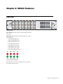
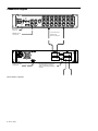
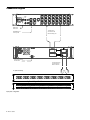
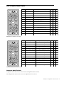
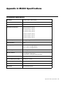
ML530 Guide System 5 Legal Notices This guide is copyrighted ©2011 by Avid Technology, Inc., (hereafter “Avid”), with all rights reserved. Under copyright laws, this guide may not be duplicated in whole or in part without the written consent of Avid. 003, 96 I/O, 96i I/O, 192 Digital I/O, 192 I/O, 888|24 I/O, 882|20 I/O, 1622 I/O, 24-Bit ADAT Bridge I/O, AudioSuite, Avid, Avid DNA, Avid Mojo, Avid Unity, Avid Unity ISIS, Avid Xpress, AVoption, Axiom, Beat Detective, Bomb Factory, Bruno, C|24, Command|8, Control|24, D-Command, D-Control, D-Fi, D-fx, D-Show, D-Verb, DAE, Digi 002, DigiBase, DigiDelivery, Digidesign, Digidesign Audio Engine, Digidesign Intelligent Noise Reduction, Digidesign TDM Bus, DigiDrive, DigiRack, DigiTest, DigiTranslator, DINR, DV Toolkit, EditPack, Eleven, HD Core, HD I/O, HD MADI, HD OMNI, HD Process, Hybrid, Impact, Interplay, LoFi, M-Audio, MachineControl, Maxim, Mbox, MediaComposer, MIDI I/O, MIX, MultiShell, Nitris, OMF, OMF Interchange, PRE, ProControl, Pro Tools, Pro Tools|HD, QuickPunch, Recti-Fi, Reel Tape, Reso, Reverb One, ReVibe, RTAS, Sibelius, Smack!, SoundReplacer, Sound Designer II, Strike, Structure, SYNC HD, SYNC I/O, Synchronic, TL Aggro, TL AutoPan, TL Drum Rehab, TL Everyphase, TL Fauxlder, TL In Tune, TL MasterMeter, TL Metro, TL Space, TL Utilities, Transfuser, Trillium Lane Labs, Vari-Fi Velvet, X-Form, and XMON are trademarks or registered trademarks of Avid Technology, Inc. Xpand! is Registered in the U.S. Patent and Trademark Office. All other trademarks are the property of their respective owners. Product features, specifications, system requirements, and availability are subject to change without notice. Guide Part Number 9329-65143-00 REV A 08/11 Documentation Feedback We are always looking for ways to improve our documentation. If you have comments, corrections, or suggestions regarding our documentation, email us at [email protected]. Contents Chapter 1. Introduction to the ML530 . . . . . . . . . . . . . . . . . . . . . . . . . . . . . . . . . . . . . . . . . . . . . . . . . . . . . . . . . . . . . . 1 Features. . . . . . . . . . . . . . . . . . . . . . . . . . . . . . . . . . . . . . . . . . . . . . . . . . . . . . . . . . . . . . . . . . . . . . . . . . . . . . . . . . . . 1 Applications . . . . . . . . . . . . . . . . . . . . . . . . . . . . . . . . . . . . . . . . . . . . . . . . . . . . . . . . . . . . . . . . . . . . . . . . . . . . . . . . . 1 System Requirements and Compatibility . . . . . . . . . . . . . . . . . . . . . . . . . . . . . . . . . . . . . . . . . . . . . . . . . . . . . . . . . . . . . 1 About This Guide. . . . . . . . . . . . . . . . . . . . . . . . . . . . . . . . . . . . . . . . . . . . . . . . . . . . . . . . . . . . . . . . . . . . . . . . . . . . . . 2 About www.avid.com . . . . . . . . . . . . . . . . . . . . . . . . . . . . . . . . . . . . . . . . . . . . . . . . . . . . . . . . . . . . . . . . . . . . . . . . . . . 2 Chapter 2. ML530 Features . . . . . . . . . . . . . . . . . . . . . . . . . . . . . . . . . . . . . . . . . . . . . . . . . . . . . . . . . . . . . . . . . . . . . . . 3 Front Panel. . . . . . . . . . . . . . . . . . . . . . . . . . . . . . . . . . . . . . . . . . . . . . . . . . . . . . . . . . . . . . . . . . . . . . . . . . . . . . . . . . 3 Back Panel . . . . . . . . . . . . . . . . . . . . . . . . . . . . . . . . . . . . . . . . . . . . . . . . . . . . . . . . . . . . . . . . . . . . . . . . . . . . . . . . . . 4 Chapter 3. Configuration and Connection . . . . . . . . . . . . . . . . . . . . . . . . . . . . . . . . . . . . . . . . . . . . . . . . . . . . . . . . . . . 5 Standard Configuration . . . . . . . . . . . . . . . . . . . . . . . . . . . . . . . . . . . . . . . . . . . . . . . . . . . . . . . . . . . . . . . . . . . . . . . . . 5 Connection Diagram . . . . . . . . . . . . . . . . . . . . . . . . . . . . . . . . . . . . . . . . . . . . . . . . . . . . . . . . . . . . . . . . . . . . . . . . . . . 6 Optional Input Patch . . . . . . . . . . . . . . . . . . . . . . . . . . . . . . . . . . . . . . . . . . . . . . . . . . . . . . . . . . . . . . . . . . . . . . . . . . . 7 Connection Diagram . . . . . . . . . . . . . . . . . . . . . . . . . . . . . . . . . . . . . . . . . . . . . . . . . . . . . . . . . . . . . . . . . . . . . . . . . . . 8 Elco 38 Input/Output Pinout. . . . . . . . . . . . . . . . . . . . . . . . . . . . . . . . . . . . . . . . . . . . . . . . . . . . . . . . . . . . . . . . . . . . . . 9 Appendix A. ML530 Specifications . . . . . . . . . . . . . . . . . . . . . . . . . . . . . . . . . . . . . . . . . . . . . . . . . . . . . . . . . . . . . . . . 11 Performance Specifications . . . . . . . . . . . . . . . . . . . . . . . . . . . . . . . . . . . . . . . . . . . . . . . . . . . . . . . . . . . . . . . . . . . . . 11 Environmental and Power Specifications . . . . . . . . . . . . . . . . . . . . . . . . . . . . . . . . . . . . . . . . . . . . . . . . . . . . . . . . . . . . 12 Physical Dimensions . . . . . . . . . . . . . . . . . . . . . . . . . . . . . . . . . . . . . . . . . . . . . . . . . . . . . . . . . . . . . . . . . . . . . . . . . . 12 Appendix B. Compliance Information . . . . . . . . . . . . . . . . . . . . . . . . . . . . . . . . . . . . . . . . . . . . . . . . . . . . . . . . . . . . . . 13 Environmental Compliance. . . . . . . . . . . . . . . . . . . . . . . . . . . . . . . . . . . . . . . . . . . . . . . . . . . . . . . . . . . . . . . . . . . . . . 13 EMC (Electromagnetic Compliance). . . . . . . . . . . . . . . . . . . . . . . . . . . . . . . . . . . . . . . . . . . . . . . . . . . . . . . . . . . . . . . . 14 Safety Compliance . . . . . . . . . . . . . . . . . . . . . . . . . . . . . . . . . . . . . . . . . . . . . . . . . . . . . . . . . . . . . . . . . . . . . . . . . . . 15 Contents iii iv ML530 Guide Chapter 1: Introduction to the ML530 The ML530 Mic-Line Interface is a 24-channel, digitally controlled analog preamplifier. The ML530 is controlled by the SC253i Interface Pilot, which is controlled from the System 5 console surface. The ML530 is packaged in a 2U rack enclosure. Applications Used in conjunction with the Pro Series AM713 analog to MADI converter, the ML530 provides multiple variable gain inputs for the System 5 or Max Air. Additional ML530s can be added if more than 24 channels of variable gain inputs are desired. Features The ML530 provides gain over a range of -12 to +72 dB in 0.5 dB increments for each channel. The ML530 also features a high-pass filter, HiZ/LowZ switch, and phantom power. Front panel LEDs provide status information for all features so the operator can quickly view the status of each input channel. Red front panel LEDs indicate signal clipping, mute, impedance, and phantom power activation. Green LEDs indicate signal presence, activation of the high-pass filter, and pad attenuator. System Requirements and Compatibility Avid can only assure compatibility and provide support for hardware and software it has tested and approved. For complete system requirements and a list of qualified computers, operating systems, hard drives, and third-party devices, visit www.avid.com/compatibility. Redundant power is supported by purchasing an additional power module. Chapter 1: Introduction to the ML530 1 About This Guide About www.avid.com This guide provides a basic overview of ML530 features and functionality. The Avid website (www.avid.com) is your best online source for information to help you get the most out of your system. The following are just a few of the services and features available. For complete instructions on connecting and configuring your system, see the System 5 Installation Guide. Product Registration Register your purchase online. Conventions Used in This Guide All of our guides use the following conventions to indicate menu choices and key commands: : Convention Action File > Save Choose Save from the File menu Control+N Hold down the Control key and press the N key Control-click Hold down the Control key and click the mouse button Right-click Click with the right mouse button The names of Commands, Options, and Settings that appear on-screen are in a different font. The following symbols are used to highlight important information: User Tips are helpful hints for getting the most from your system. Important Notices include information that could affect your data or the performance of your system. Shortcuts show you useful keyboard or mouse shortcuts. Cross References point to related sections in this guide and other Avid guides. 2 ML530 Guide Support and Downloads Contact Avid Customer Success (technical support); download software updates and the latest online manuals; browse the Compatibility documents for system requirements; search the online Knowledge Base or join the worldwide Avid user community on the User Conference. Training and Education Study on your own using courses available online or find out how you can learn in a classroom setting at a certified Avid training center. Products and Developers Learn about Avid products; download demo software or learn about our Development Partners and their plug-ins, applications, and hardware. News and Events Get the latest news from Avid or sign up for a demo. Chapter 2: ML530 Features Front Panel 1 2 3 4 5 6 7 8 9 10 11 12 13 14 15 16 17 18 19 20 21 22 23 24 MIC LINE INTERFACE ML 530 ML530 front panel Power Switch The power switch, on the lower right, turns the unit on/off. Status LEDs Eight LEDs provide status information for each of the 24 channels: • Clip: Signal clipping (red) • Mute: Channel muted (red) • HiZ: High impedance (red) • 48V: Phantom power (red) • Sig: Signal present (green) • HPF: High-pass filter (green) • Phase: Phase invert (green) • Pad: 12 dB attenuation (green) Clip Mute LowZ 48V Sig HPF Phase Pad Front panel Channel Status LEDs Since the ML530 is software controlled, the power switch is the only front panel control. Chapter 2: ML530 Features 3 Back Panel ML530 OUTPUTS INPUTS 1 -12 CONTROL ML530 front panel Inputs (38-pin Elco) 24 inputs are provided on two 38-pin Elco connectors. The level of all signals input at these ports can be boosted or attenuated. In standard configuration, the input cable is configured by the customer. Elco connectors and pins are provided. Outputs (38-pin Elco) 24 outputs are provided on two 38-pin Elco connectors. The supplied output cables fan out to two sets of 12 male XLRs for connection to the AM713 Analog to MADI converter. Control (DB-15) Input for digital control signal from PC253i Digital Pilot. Signal format is Euphonix TCC bi-directional serial protocol. All switching and gain controls are communicated via this connector. AC Line In (IEC) and Fuse Tray The power connector accepts standard IEC power cords. 90–250 VAC 110, 220, or 240 VAC, 50/60 Hz can be applied at this connector. 4 ML530 Guide 13-24 Chapter 3: Configuration and Connection Standard Configuration recommended locations Digital Core 1 2 A 3 AM713 A Machine Room B Control Room B Use relative locations to determine cable lengths 4 4 B ML530 5,6 ML530 standard cable diagram Elco crimp pins and hoods for inputs are supplied in accessory cable kits. Input cabling is not included. Cable Specifications Cable Qty Description 10M Part # 20M Part# Accessory cable kits by special order 936-07083-01 936-07155-01 Length 1 1 MADI Output: RG59 75 coax 032-07230-00 032-07306-00 2 1 AES/EBU Sync: one male XLR <> one female XLR 030-07085-01 030-07153-01 3 1 TCC Control from 253i Interface Pilot 030-06983-01 030-06985-01 4 2 ML530 Analog Out one Elco 38 <> twelve male XLR 5 2 Elco 38-Pin Connector w/hood 100-02099-00 NA 6 80 Elco Crimp Pins 100-02100-00 NA 030-7108-01 .5 m The standard lengths specified in the table above are supplied so the mic-line interface can be located in the control room. Cable kits are ordered separately. Custom lengths are available. Chapter 3: Configuration and Connection 5 Connection Diagram AM713 MADI OUT 1 MADI out to Studio Hub 2 12 male XLR to one male Elco 38 Mic/Line Analog Out AES/EBU Sync In from Sync DA 4 Control from PC253i Interface Pilot ML530 standard configuration 6 ML530 Guide 3 Elco crimp pins and hoods for user inputs are supplied in accessory cable kits. Input cabling supplied by customer 4 5, 6 Optional Input Patch recommended locations Digital Core 1 2 A 3 AM713 4 B Note: The optional input patchbay ha capacity to provide input patching to channels or two ML530 Interfaces. A additional set of cable D is required f second ML530 interface. 4 B ML530 5 D A 5 D Mic-Line Input Patch B, C Input Patch cable diagram The optional input patchbay has the capacity to provide input patching to 48 channels or two ML530 interfaces. An additional set of cable D (below) is required for the second ML530 interface. Patchbay, cables, and pins are ordered separately. Cable Specifications Part Qty Description Part # Length A 1 Tie Line Patch 950-03770-01 NA B* 2 Elco 38-Pin Connector w/hood 100-02099-00 NA C* 80 Elco Crimp Pins 100-02100-00 NA D** 2 ML530 Analog Out one male Elco 38 <> one male Elco 38 030-07158-01 2m * Elco hoods and crimp pins are included in standard 10m and 20m accessory cable kits. ** 10m cable available, one male Elco 38 <> one male Elco 38, part #030-6913-01. Chapter 3: Configuration and Connection 7 Connection Diagram AM713 MADI OUT 1 MADI out to Studio Hub 2 12 male XLR to one male Elco 38 Mic/Line Analog Out AES/EBU Sync In from Sync DA 4 Control from PC253i Interface Pilot 4 3 one male Elco 38 to one male Elco 38 Patch to Mic/Line D D B,C A - Optional Patchbay Upper 37-48 Upper 25-36 USER USER Lower 37-48 USER Lower 25-36 Upper 13-24 Upper 1-12 Lower 13-24 USER USER USER USER Lower 1-12 USER Optional Input Patch 1 2 3 4 5 6 7 8 9 10 11 12 13 14 15 16 17 18 19 20 21 22 23 24 25 26 27 28 29 30 31 32 33 34 35 36 37 38 39 40 41 42 43 44 45 46 47 48 1 2 3 4 5 6 7 8 9 10 11 12 13 14 15 16 17 18 19 20 21 22 23 24 25 26 27 28 29 30 31 32 33 34 35 36 37 38 39 40 41 42 43 44 45 46 47 48 Mic/Line Inputs Input patch configuration 8 ML530 Guide Elco 38 Input/Output Pinout A B C F E L R H N J P T S W X Y B B A A D D J J E E K K F F + - G 1 Mic In 1 / Mic In 13 From studio Mic 1 / 13 A E L 2 Mic In 2 / Mic In 14 From studio Mic 2 / 14 B F M 3 Mic In 3 / Mic In 15 From studio Mic 3 / 15 C H N 4 Mic In 4 / Mic In 16 From studio Mic 4 / 16 D J P 5 Mic In 5 / Mic In 17 From studio Mic 5 / 17 DD JJ PP 6 Mic In 6 / Mic In 18 From studio Mic 6 / 18 EE KK RR 7 Mic In 7 / Mic In 19 From studio Mic 7 / 19 FF LL SS 8 Mic In 8 / Mic In 20 From studio Mic 8 / 20 HH MM TT 9 Mic In 9 / Mic In 21 From studio Mic 9 / 21 R S V 10 Mic In 10 / Mic In 22 From studio Mic 10 / 22 T U W 11 Mic In 11 / Mic In 23 From studio Mic 11 / 23 X Z AA 12 Mic In 12 / Mic In 24 From studio Mic 12 / 24 Y BB CC C C H H M M L L P P Wiring Instruction & Description U V Z Signal D G M Num N N S S R R T T ML530 In 1/In 2 pinout: Elco 38 socket A B C F E L R Signal Wiring Instruction & Description + - G 1 Mic Pre Out 1 / Out 13 To AM713 Analog In 1 / In 13 A E L 2 Mic Pre Out 2 / Out 14 To AM713 Analog In 2 / In 14 B F M 3 Mic Pre Out 3 / Out 15 To AM713 Analog In 3 / In 15 C H N 4 Mic Pre Out 4 / Out 16 To AM713 Analog In 4 / In 16 D J P 5 Mic Pre Out 5 / Out 17 To AM713 Analog In 5 / In 17 DD JJ PP 6 Mic Pre Out 6 / Out 18 To AM713 Analog In 6 / In 18 EE KK RR 7 Mic Pre Out 7 / Out 19 To AM713 Analog In 7 / In 19 FF LL SS 8 Mic Pre Out 8 / Out 20 To AM713 Analog In 8 / In 20 HH MM TT 9 Mic Pre Out 9 / Out 21 To AM713 Analog In 9 / In 21 R S V 10 Mic Pre Out 10 / Out 22 To AM713 Analog In 10 / In 22 T U W 11 Mic Pre Out 11 / Out 23 To AM713 Analog In 11 / In 23 X Z AA 12 Mic Pre Out 12 / Out 24 To AM713 Analog In 12 / In 24 Y BB CC D G H N M Num J P T S U W V Y X B B A A Z D D J J E E K K P P F F H H M M L L R R C C S S N N T T ML530 Out 1/Out 2 pinout: Elco 38 socket Connector Specifications 38-pin male w/ hood Elco P/N 00-8016-038000-519 (Euphonix P/N 100-02099) Use crimp pins Elco P/N 60-8017-031300-339 (Euphonix P/N 100-02100) Chapter 3: Configuration and Connection 9 10 ML530 Guide Appendix A: ML530 Specifications Performance Specifications Gain Range -12 dB to 72 dB in 0.5 dB increments Phantom Power +48 V ±2% (Switched per channel) Maximum Input Level 41 dB (Pad inserted, unity gain, @1 kHz, @1% THD+N) Differential Input Impedance 200 k (Hi Z, Pad off, +48V off) 200 k (Hi Z, Pad on, +48V off) 12.7 k (Hi Z, Pad on, +48V on) 12.7 k (Hi Z, Pad off, +48V on) 1.5 k (Lo Z, Pad off, +48V off) 1.5 k (Lo Z, Pad on, +48V off) 1.4 k (Lo Z, Pad on, +48V on) 1.4 k (Lo Z, Pad off, +48V on) Maximum Output Level 29 dB (@1 kHz, @1% THD+N) Output Impedance 100 Frequency Response 10 Hz – 60 kHz (-0.5 dB @ unity gain) 10 Hz – 50 kHz (-0.5 dB @ 30 dB gain) 10 Hz – 40 kHz (-0.5 dB @ 66 dB gain) Gain Accuracy ±0.15 dB (@1 kHz) Distortion (THD+N) 0.004% (@ 1 kHz @ 0 dB gain with +13.5 dB applied, 22 kHz filtered) < 0.02% (20 Hz – 20 kHz @ 13.5 dB 80 kHz filtered) Equivalent Input Noise (EIN) -127 dB (@66 dB gain, 22 Hz – 22 kHz filtered, Low Z mode, 150 source) Common Mode Rejection (CMR) >50 dB (10 Hz – 20 kHz) Phase Linearity ±10° (25 Hz – 20 kHz) High-pass Filter 80 Hz 18 dB/octave switched per channel Phase Invert 180° switched per channel Appendix A: ML530 Specifications 11 Environmental and Power Specifications Operating Temperature 5–35°C Power Requirements 90–250 VAC, 50/60Hz Power Consumption 100 W Physical Dimensions Height 3.5 inches Width 19 inches Depth 18.6 inches Weight 17 lb 12 ML530 Guide Appendix B: Compliance Information Environmental Compliance Disposal of Waste Equipment by Users in the European Union Proposition 65 Warning This product contains chemicals, including lead, known to the State of California to cause cancer and birth defects or other reproductive harm. Wash hands after handling. Perchlorate Notice This product may contain a lithium coin battery. The State of California requires the following disclosure statement: “Perchlorate Material – special handling may apply, See www.dtsc.ca.gov/hazardouswaste/perchlorate.” This symbol on the product or its packaging indicates that this product must not be disposed of with other waste. Instead, it is your responsibility to dispose of your waste equipment by handing it over to a designated collection point for the recycling of waste electrical and electronic equipment. The separate collection and recycling of your waste equipment at the time of disposal will help conserve natural resources and ensure that it is recycled in a manner that protects human health and the environment. For more information about where you can drop off your waste equipment for recycling, please contact your local city recycling office or the dealer from whom you purchased the product. Recycling Notice Appendix B: Compliance Information 13 EMC (Electromagnetic Compliance) Avid declares that this product complies with the following standards regulating emissions and immunity: • FCC Part 15 Class A • EN55103-1 E4 • EN55103-2 E4 • AS/NZS CISPR 22 Class A • CISPR 22 Class A FCC Compliance for United States Communication Statement Note: This equipment has been tested and found to comply with the limits for a Class A digital device, pursuant to part 15 of the FCC Rules. These limits are designed to provide reasonable protection against harmful interference when the equipment is operated in a commercial environment. This equipment generates, uses, and can radiate radio frequency energy and, if not installed and used in accordance with the instruction manual, may cause harmful interference to radio communications. Operation of this equipment in a residential area is likely to cause harmful interference in which case the user will be required to correct the interference at his own expense. Any modifications to the unit, unless expressly approved by Avid, could void the user's authority to operate the equipment. 14 ML530 Guide Australian Compliance N1709 Canadian Compliance This Class A digital apparatus meets all requirements of the Canadian Interference-Causing Equipment Regulations. Cet appareil numérique de la classe A respecte toutes les exigences du Règlement sur le material brouilleur du Canada. CE Compliance (EMC and Safety) Avid is authorized to apply the CE (Conformité Europénne) mark on this compliant equipment thereby declaring conformity to EMC Directive 2004/108/EC and Low Voltage Directive 2006/95/EC. Safety Compliance Safety Statement This equipment has been tested to comply with USA and Canadian safety certification in accordance with the specifications of UL Standards: UL 60950-1:2007, 2nd Ed and CAN/CSA-22.2 No. 60950-1-07, 2nd Ed. Avid Inc., has been authorized to apply the appropriate NRTL mark on its compliant equipment. Warning 13) Unplug this equipment during lightning storms or when unused for long periods of time. 14) Refer all servicing to qualified service personnel. Servicing is required when the equipment has been damaged in any way, such as power-supply cord or plug is damaged, liquid has been spilled or objects have fallen into the equipment, the equipment has been exposed to rain or moisture, does not operate normally, or has been dropped. 15) For products that are a Mains powered device: The equipment shall not be exposed to dripping or splashing and no objects filled with liquids (such as vases) shall be placed on the equipment. Warning! To reduce the risk of fire or electric shock, do not expose this equipment to rain or moisture. 16) For products containing a lithium battery: CAUTION! Danger of explosion if battery is incorrectly replaced. Replace only with the same or equivalent type. 17) For products with a power switch: It should remain accessible after installation. 18) The equipment shall be used at a maximum ambient temperature of 40° C. Important Safety Instructions 1) Read these instructions. 19) This unit is provided with a power supply cord set suitable for 120V AC input only (for U.S.A.and Canada). For other than U.S.A. and Canada, a qualified person must provide for use with this unit, an appropriate, approved power supply cord set which is in compliance with the end use country requirements and has a minimum cross-sectional area of 1.0mm2. 2) Keep these instructions. 20) For units with more than one power cord: 3) Heed all warnings. CAUTION: This unit has more than one power supply cord. Disconnect two power supply cords before servicing to avoid electrical shock. 4) Follow all instructions. 5) Do not use this equipment near water. 6) Clean only with dry cloth. 7) Do not block any ventilation openings. Install in accordance with the manufacturer’s instructions. 8) Do not install near any heat sources such as radiators, heat registers, stoves, or other equipment (including amplifiers) that produce heat. 9) Do not defeat the safety purpose of the polarized or grounding-type plug. A polarized plug has two blades with one wider than the other. A grounding type plug has two blades and a third grounding prong. The wide blade or the third prong are provided for your safety. If the provided plug does not fit into your outlet, consult an electrician for replacement of the obsolete outlet. ATTENTION: Cet appareil comporte plus d’un cordon d’alimentation. Afin de prévenir les chocs électriques, débrancher les deux cordons d’alimentation avant de faire le dépannage. 21) For products with an operator-accessible fuse: CAUTION: For continued protection against risk of fire, replace only with same type and rating of fuse. ATTENTION: Pour ne pas compromettre la protection contre les risques d’incendie, remplacer par un fusible de même type et de même caractéristiques nominales. 10) Protect power cords from being walked on or pinched particularly at plugs, convenience receptacles, and the point where they exit from the equipment. 11) Only use attachments/accessories specified by the manufacturer. 12) For products that are not rack-mountable: Use only with a cart, stand, tripod, bracket, or table specified by the manufacturer, or sold with the equipment. When a cart is used, use caution when moving the cart/equipment combination to avoid injury from tip-over. Appendix B: Compliance Information 15 16 ML530 Guide Avid Technical Support (USA) Product Information 2001 Junipero Serra Boulevard Daly City, CA 94014-3886 USA Visit the Online Support Center at www.avid.com/support For company and product information, visit us on the web at www.avid.com


![Stage 48 - akmedia.[bleep]digidesign.](http://vs1.manualzilla.com/store/data/007247961_1-0fc36f720a3108317a47260e3de3799a-150x150.png)