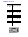
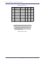
1
MC524
Monitor Interface
Installation Manual
Document Revision: A
Part Number: 840-11311-01
Release Date: August 2010
Euphonix is Avid. Learn more at www.avid.com
Regulatory and Safety Notices
FCC Notice
Part 15 of the Federal Communication Commission Rules and Regulations has established Radio
Frequency (RF) emission limits to provide an interference free radio frequency spectrum. Many
electronic devices produce RF energy incidental to their intended purpose.
These rules place electronic equipment into two classes, A and B, depending on the intended use.
Class A devices are those that may be expected to be installed in a business or commercial environment.
Class B devices are those that may be expected to be installed in a home or residential environment. The
FCC requires devices in both classes to be labeled with the interference likelihood and additional
operating instructions. The rating label on the equipment will show which class the product is (A or B).
Class A product will not have an FCC logo. Class B equipment will have an FCC logo. The information
statements differ on the two classes.
Class A Equipment
This equipment has been tested and found to comply with the limits for a Class A digital device,
pursuant to Part 15 of the FCC rules. These limits are designed to provide reasonable protection against
harmful interference when the equipment is operated in a commercial environment. This equipment
generates, uses, and can radiate radio frequency energy and, if not installed and used in accordance
with the instructions, may cause harmful interference to radio communications. Operation of this
equipment in a residential area is likely to cause harmful interference, in which case the user will be
required to correct the interference at personal expense.
Euphonix is Avid. Learn more at www.avid.com
Modifications
The FCC requires the user to be notified that any changes or modifications made to Avid hardware that
are not expressly approved by Avid Technology may void the user’s authority to operate the equipment.
Cables
Connections to Avid hardware must be made with shielded cables with metallic RFI/EMI connector
hoods in order to maintain compliance with FCC Rules and Regulations.
PRODUCTS WITH MULTIPLE POWER INPUTS:
WARNING: Each power input is intended to be connected to a separate branch circuit. Risk of high
leakage exists if multiple inputs are connected to a single source and protective earth is not present. A
QUALIFIED SERVICE PERSON shall verify that each socket-outlet from which the equipment is to be
powered provides a connection to the building protective earth. If any do not provide this connection,
the QUALIFIED SERVICE PERSON shall arrange for the installation of a PROTECTIVE EARTHING
CONDUCTOR from the separate protective earthing terminal to the protective earth wire in the building.
Canadian ICES-003
Class A Equipment
This Class A digital apparatus meets all requirements of the Canadian Interference-Causing Equipment
Regulations.
Cet appareil numérique de la classe A respecté toutes les exigences du Règlement sur le matériel
brouilleur du Canada.
Euphonix is Avid. Learn more at www.avid.com
European Union Declaration of Conformity
Declaration of conformity
Konformitätserklärung
Déclaration de conformité
Declaración de Confomidad
Verklaring de overeenstemming
Dichiarazione di conformità
We/Wir/ Nous/WIJ/Noi:
Avid Technology
1925 Andover Street
Tewksbury, MA, 01876 USA
European Contact: Nearest Avid Sales and Service Office or
Avid Technology International B.V.
Sandyford Industrial Estate
Unit 38, Carmanhall Road
Dublin 18, Ireland
declare under our sole responsibility that the product,
erklären, in alleniniger Verantwortung,daß dieses Produkt,
déclarons sous notre seule responsabilité que le produit,
Euphonix is Avid. Learn more at www.avid.com
declaramos, bajo nuestra sola responsabilidad, que el producto,
verklaren onder onze verantwoordelijkheid, dat het product,
dichiariamo sotto nostra unica responsabilità, che il prodotto,
Product Name(s) : Monitor Interface
Model Number(s): MC524
Product Options: This declaration covers all options for the above product(s).
to which this declaration relates is in conformity with the following standard(s) or other normative
documents.
auf das sich diese Erklärung bezieht, mit der/den folgenden Norm(en) oder Richtlinie(n)
übereinstimmt.
auquel se réfère cette déclaration est conforme à la (aux) norme(s) ou au(x) document(s)
normatif(s).
al que se refiere esta declaración es conforme a la(s) norma(s) u otro(s) documento(s)
normativo(s).
waarnaar deze verklaring verwijst, aan de volende norm(en) of richtlijn(en) beantwoordt.
a cui si riferisce questa dichiarazione è conforme alla/e seguente/i norma/o documento/i
normativo/i.
The requirements of the European Council:
Safety: Directive 2006/95/EC
EN 60065:2002 /A1:2006
EMC: Directive 2004/108/EC
EN 55103-1:1996
EN 55103-2:1996
Euphonix is Avid. Learn more at www.avid.com
LED Safety Notices
Avid hardware might contain LED or Laser devices for communication use. These devices are compliant
with the requirements for Class 1 LED and Laser Products and are safe in the intended use. In normal
operation the output of these laser devices does not exceed the exposure limit of the eye and cannot
cause harm.
Standard to which conformity is declared: (IEC 60825-1)
Optical connections are located on the rear panel and are typically labeled “Optical” or “SPDIF/ADAT.”
The exact location of optical connections is identified more clearly elsewhere in the documentation for
the Avid hardware device.
Euphonix is Avid. Learn more at www.avid.com
Disposal of Waste Equipment by Users in the
European Union
Rack-mount Requirements
The following rack-mount requirements are listed below:
• Elevated Operating Ambient — If installed in a closed or multi-unit rack assembly, the operating ambient
temperature of the rack environment might be greater than room ambient. Therefore, consider installing the
equipment in an environment compatible with the maximum ambient temperature (Tma) specified by the
manufacturer.
• Reduced Air Flow — Installation of the equipment in a rack should be such that the amount of air flow
required for safe operation of the equipment is not compromised. Do not block vents.
• Mechanical Loading — Mounting of the equipment in the rack should be such that a hazardous condition is
not achieved due to uneven mechanical loading.
• Circuit Overloading — Consideration should be given to the connection of the equipment to the supply
circuit and the effect that overloading of the circuits might have on overcurrent protection and supply wiring.
Appropriate consideration of equipment nameplate ratings should be used when addressing this concern.
• Reliable earthing — Reliable earthing of rack-mounted equipment should be maintained. Particular
attention should be given to supply connections other than direct connections to the branch circuit (for
example, use of power strips).
Euphonix is Avid. Learn more at www.avid.com
Lithium Battery Replacement
If a battery is supplied in this Avid product it must only be replaced by qualified personnel. Contact Avid
Customer Support for assistance.
WARNING
Danger of explosion if battery is incorrectly replaced. Replace with only the same or equivalent type
recommended by the manufacturer. Dispose of used batteries according to the manufacturer’s
instructions.
ADVARSEL!
Lithiumbatteri - Eksplosionsfare ved fejlagtig håndtering. Udskiftning må kun ske med batteri af
samme fabrikat og type. Levér det brugte batteri tilbage til leverandøren.
ADVARSEL!
Lithiumbatteri - Eksplosjonsfare. Ved utskifting benyttes kun batteri som anbefalt av
apparatfabrikanten. Brukt batteri returneres apparatleverandøren.
VARNING
Explosionsfara vid felaktigt batteribyte. Använd samma batterityp eller en ekvivalent typ som
rekommenderas av apparattillverkaren. Kassera använt batteri enligt fabrikantens instruktion.
VAROITUS
Paristo voi räjähtää, jos se on virheellisesti asennettu. Vaihda paristo ainoastaan laitevalmistajan
suosittelemaan tyyppiin. Hävitä käytetty paristo valmistajan ohjeiden mukaisesti.
Euphonix is Avid. Learn more at www.avid.com
Euphonix MC524 Monitor Interface Operation Manual
Table of Contents
List of Figures ....................................................................................................................... vi
List of Tables ........................................................................................................................ vii
Overview...............................................................................................................8
Features .................................................................................................................8
Mic Inputs..................................................................................................8
Line Inputs.................................................................................................8
Line Outputs ..............................................................................................8
Applications ..........................................................................................................8
Front Panel ............................................................................................................9
Rear Panel ...........................................................................................................10
Specifications ......................................................................................................11
Phantom Power: 48 V Jumper Settings ...................................................13
User Reference....................................................................................................14
Standard Configuration ...........................................................................14
Input/Output Connections .......................................................................17
Optional Configurations ..........................................................................22
v
Euphonix MC524 Monitor Interface Operation Manual
List of Figures
1
MC524 Front Panel .............................................................................................................9
2
MC524 Rear Panel ............................................................................................................10
3
Pins to set Phantom Power ................................................................................................13
4
MC524 Standard Cable Diagram ......................................................................................14
5
MC524 Standard Configuration ........................................................................................16
6
Elco 38 Connector ............................................................................................................17
7
Elco 90 Connector ............................................................................................................18
8
Elco 90 Connector ............................................................................................................19
9
Elco 90 Connector ............................................................................................................20
10
DB-25 Connector ..............................................................................................................21
11
Monitor Output Patch Cable Diagram ..............................................................................22
12
Monitor Output Patch Configuration ................................................................................23
13
Monitor Insert Patch Cable Diagram ................................................................................24
14
Monitor Insert Patch Configuration ..................................................................................25
15
Rear View of Elco Male 38-pin Connector (Insert pins from this side) ...........................26
vi
Euphonix MC524 Monitor Interface Operation Manual
List of Tables
1
MC524 Performance Specifications .............................................................................. 11
2
MC524 Environmental and Power Specifications ......................................................... 12
3
MC524 Physical Dimensions ......................................................................................... 12
4
Upper and Lower Board Jumper Mappings ................................................................... 13
5
MC524 Standard Cable Specification ............................................................................ 15
6
In 1 Elco 38 Pinout ........................................................................................................ 17
7
In 2 Elco 90 Pinout ........................................................................................................ 18
8
Out 1 Elco 90 Pinout ...................................................................................................... 19
9
Out 2 Elco 90 Pinout ...................................................................................................... 20
10
Out 3 DB-25 Pinout ....................................................................................................... 21
11
Monitor Output Patch Cable Specifications .................................................................. 22
12
Monitor Insert Patch Cable Specification ...................................................................... 24
13
Tie Line Patch Elco 38 Pinout ....................................................................................... 26
vii
Euphonix MC524 Monitor Interface Operation Manual
Overview
The MC524 Monitor Interface centralizes control room monitor and communication
signals in one box and places them under remote control by the system operator. The
MC524 is a digitally controlled analog signal router and level control device with a built
in Talk Back microphone circuit in a 2RU enclosure.
The MC524 receives the 22 monitor busses and two solo busses from the System 5
monitor matrix output and provides a control room output to three speaker sets, four
SLS/Cue monitor outputs as well as post preamp talk and listen mic outputs.
The SC253i Interface Pilot digitally controls the MC524 over a 15-pin control cable with
a maximum length 100 m. The system operator can control all MC524 parameters from
the System 5 control surface. There is only one MC524 in a System 5 configuration.
Features
Mic Inputs
Mic level inputs are provided for four Listen and two Talk mics on a 38-pin Elco connector. An analog gain stage provides boost or attenuation for mic level signals. Talk
Back mic inputs include phantom power and a compressor.
Line Inputs
There are 24 line level inputs for Control Room feeds, Monitor A–D, and Solo. Line
level inputs have attenuation only.
Line Outputs
Line outputs are on 90-pin Elco connectors for eight Monitor A (up to 7.1 monitoring),
two each for Monitor B–D, eight Control Room Main (up to 7.1 monitoring), six Control Room Alt 1 (up to 5.1 monitoring), two Control Room Alt 2, four Listen preamp,
two Talk preamp out, and two Solo outputs.
All cabling is provided from the digital input to the final user connections of the output
patchbay. See the cabling diagrams in the User Reference section.
Applications
The MC524 allows the System 5 engineer to adjust all Control Room communications
(Level Control, Cut, Dim and speaker selection) from the console Center Section. We
recommend installing the MC524 in the Control Room.
8
Euphonix MC524 Monitor Interface Operation Manual
Front Panel
MONITOR-COMMS INTERFACE
MC
524
Figure 1 MC524 Front Panel
Power Switch: The power switch turns the unit on/off.
Since the MC524 is digitally controlled via software, the power switch is the only front
panel control.
9
Euphonix MC524 Monitor Interface Operation Manual
Rear Panel
Figure 2 MC524 Rear Panel
In 1 (38-pin Elco): Talk Back, Listen Back and Mic inputs. This connector receives
four stereo listen channels and two stereo talk mic inputs. All signals input at this port
can be level boosted or attenuated. In standard patch configuration, input cable fans out
to 12 XLR females.
In 2 (90-pin Elco): Control Room Busses, Monitor A, B, C, D, and Solo busses inputs.
This connector receives eight Monitor A channels, and two each channels for Monitor
B, C, D. Signals input at this port can only be level attenuated. In standard configuration
these signals are fed from the AM713 converter.
Out 1 (90-pin Elco): Monitor A, B, C, D Speaker outputs. This connector outputs eight
Control Room channels, eight Monitor A channels, and two each channels for Monitor
B, C, D, and Solo. The output cable fans out to two 38-pin Elco connectors for the Euphonix Patchbay.
Out 2 (90-pin Elco): This connector outputs eight Control Room Main channels, six
Control Room Alt 1 channels, two Control Room Alt 2 channels, four Listen pre, two
talk pre and two Solo channels. The output cable fans out to two 38-pin Elco connectors
for the Euphonix Patchbay.
Out 3 (DB-25 female): This connector outputs four Listen pre, two Talk Back pre, and
two Solo channels, eight Monitor A channels, and two channels each for Monitor B, C,
D, and Solo. The output cable fans out to eight male XLR connectors.
Control (DB-15): Input for digital control signal from Digital Pilot. Signal format is
Euphonix TCC bi-directional serial protocol. All patching, switching, and gain controls
are communicated via this connection as well as MC524 IP address.
AC Line In (IEC) and Fuse Tray: The power connector accepts standard IEC power
cords. 110, 220, or 240 VAC, 50/60 Hz can be applied at this connector.
10
Euphonix MC524 Monitor Interface Operation Manual
Specifications
Table 1 MC524 Performance Specifications
Main Inputs
Solo, CR 7, Mon A, B, C, D
Description
Electronically balanced, transformerless, differential input
Gain
Variable from 0 dB (unity) to -72 dB
Optimum Input Levels
Set to 0 dBFS = +27 dBU. Designed to be fed from Euphonix MA703 DAC.
Maximum Input Level Before Clipping
+28 dBU (sine wave)
Maximum Input Voltages
±16 VDC, ±25 VAC (common mode), ±50 VAC (differential)
Input impedance
10 kΩ ±10% each leg, 20 Hz – 20 kHz
CMRR
>40 dB (50 dB typical), 20 Hz – 20 kHz
Talk Back And Listen Mic Inputs
T1, T2, L1–L4
Description
Electronically balanced, transformerless, differential input with automatic level
optimization
Gain
AGC circuit optimizes front end gain to produce approx. +8 dBU signal; this is
variable from +8 to -64 dBU at the monitor outputs
Maximum Input Level Before Clipping
10 dBU (sine wave)
Maximum Input Voltages
±50 VDC, ±2.5 VAC (common mode), ±5 VAC (differential)
Phantom Power
48 V available, link selectable on PCB
Frequency Response
Attenuated LF and HF response, -3 dB at 200 Hz and 10 kHz
Monitor Outputs
Description
Electronically balanced and floating, differential output
Maximum Output Level
+28 dBU (sine wave)
Output Impedance
100 Ω ±10%, balanced or unbalanced, 20 Hz – 20 kHz
DC Offset
< ±5 mV with respect to chassis GND
Full Signal Path
Main Input To Monitor Output
Frequency Response
0/-0.4 dB, 20 Hz – 20 kHz (ref. 1 kHz)
Signal Breakthrough with Full Cut
<-110 dB, 20 Hz – 20 kHz
Distortion
<0.005%, 20 Hz – 20 kHz, +15 dBU output level
Crosstalk
< -100 dB at 1 kHz; < -90 dB at 20 kHz
Output Noise
<-90 dBU RMS (unweighted); >117 dB of dynamic range at unity gain
11
Euphonix MC524 Monitor Interface Operation Manual
Table 2 MC524 Environmental and Power Specifications
Operating Temperature
5–35°C
Power Requirements
100–240 VAC, 50/60Hz
Power Consumption
1A
Table 3 MC524 Physical Dimensions
Height
3.5 inches
Width
19 inches
Depth
18.6 inches
Weight
17 lb
Leave about six inches behind the MC524 for cable connections.
12
Euphonix MC524 Monitor Interface Operation Manual
Authorized Service Personnel Only:
Phantom Power: 48 V Jumper Settings
Phantom power is enabled by fitting the link to short pins 1 and 2. If not required (i.e.,
using a dynamic mic) then it should be set to short pins 2 and 3. Pin 1 position can be
ascertained by looking for the square pad on the solder side.
Figure 3 Pins to set Phantom Power
Note that the standard Talk Back mic on the console (wired to T1) is a condenser type
which requires phantom power. Table 4 shows the mapping of the jumpers:
Table 4 Upper and Lower Board Jumper Mappings
Lower Board
Upper Board
J1
Talkback 1 (T1)
J1
Listen 2 (L2)
J2
Talkback 2 (T2)
J2
Listen 3 (L3)
J3
Listen 1 (L1)
J3
Listen 4 (L4)
13
Euphonix MC524 Monitor Interface Operation Manual
User Reference
Standard Configuration
recommended locations
Digital Core
2
1
A
3
MA703
A
Machine Room
B
Control Room
B
Use relative locations to
determine cable lengths
44
5
B
MC524
7,8
76
Figure 4 MC524 Standard Cable Diagram
The standard lengths specified in Table 5 are supplied so the monitor interface can be
located in the control room. Custom lengths are available and cable kits must be ordered
separately.
14
Euphonix MC524 Monitor Interface Operation Manual
Table 5 MC524 Standard Cable Specification
Cable
Qty
Description
10M Part #
20M Part#
Accessory cable kits by special
order
936-07084-01
936-07156-01
Length
1
1
MADI Output: RG59 75 Ω coax
032-07230-00
032-07306-00
2
1
AES/EBU Sync:
one male XLR <> one female XLR
030-07085-01
030-07153-01
3
1
TCC Control from 253i Interface
Pilot
030-06983-01
030-06985-01
4
1
TB/LB Mic:
one male Elco 38 <> 12 female XLR
030-06919-01
2m
5
1
CR/Mon/Solo Bus:
one male Elco 90 <> 24 female XLR
030-07225-01
1m
6
1
TB and LB Mic Pre Out:
one DB-25 <> eight male XLR
032-07038-00
3m
7
2
Elco 90-pin Connector w/hood
100-07470-00
NA
8
180
Elco Crimp Pins
100-02100-00
NA
15
Euphonix MC524 Monitor Interface Operation Manual
MA703
MADI
IN
DIGITAL
OUTPUTS
ANALOG
OUTPUTS
1
MADI in from Core
2
2
24XLRFto 1xEM90
Monitor bus outs
from MA703
AES/EBU Sync In
from Studio Hub
5
12XLRF<>1xEM38
4 Listen &
2 Talk Mic inputs
Control from Digital
Interface Pilot
4
8 - Control Room
8 - Mon A
2 - Mon B
2 - Mon C
2 - Mon D
2 - Solo
8xXLRM to DB25
3
6
8 - Mon A
2 - Mon B
2 - Mon C
2 - Mon D
7, 8
2 - Solo out
2 - Talk pre out
4 - Listen pre out
8 - CR Main out
6 - CR Alt 1 out
2 - CR Alt 2 out
Connectors and pins provided
Figure 5 MC524 Standard Configuration
16
2 - TB pre out
4 - Listen pre out
2 - Solo out
(TB1 returns to
core for slate)
Euphonix MC524 Monitor Interface Operation Manual
Input/Output Connections
Table 6 In 1 Elco 38 Pinout
Crk #
Designator
24 X 32
High
Low
Gnd
1
M1
Talk 1
A
E
L
2
M2
Talk 2
B
F
M
3
M3
Listen 1
C
H
N
4
M4
Listen 2
D
J
P
5
M5
Listen 3
DD
JJ
PP
6
M6
Listen 4
EE
KK
RR
7
FF
LL
SS
8
HH
MM
TT
9
R
S
V
10
T
U
W
11
X
Z
AA
12
Y
BB
CC
B
A
F
E
H
J
T
S
R
Y
X
B
B
A
A
D
D
J
J
F
F
E
E
K
K
P
P
U
W
V
Z
K
P
N
M
L
D
C
L
L
R
R
C
C
H
H
M
M
S
S
N
N
T
T
Figure 6 Elco 38 Connector
17
Euphonix MC524 Monitor Interface Operation Manual
Table 7 In 2 Elco 90 Pinout
Low
Gnd
1
L3
Cntrl Rm (L)
A
H
R
2
L4
Cntrl Rm (C)
B
J
S
3
L5
Cntrl Rm (R)
C
K
T
4
L6
Cntrl Rm (Sl)
D
L
U
5
L7
Cntrl Rm (Sr)
E
M
V
6
L8
Cntrl Rm (B)
F
N
W
7
L9
Cntrl Rm (Li)
X
AE
AM
8
L10
Cntrl Rm (Ri)
Y
AF
AN
9
L11
Mon A (L)
Z
AH
AP
10
L12
Mon A (C)
AA
AJ
AR
11
L13
Mon A (R)
AB
AK
AS
12
L14
Mon A (Sl)
AC
AL
AT
13
L15
Mon A (Sr)
BJ
BS
BY
14
L16
Mon A (B)
BK
BT
BZ
15
L17
Mon A (Li)
BL
BU
CA
16
L18
Mon A (Ri)
BM
BV
CB
17
L19
Mon B (L)
BN
BW
CC
18
L20
Mon B (R)
BP
BX
CD
19
L21
Mon C (L)
CF
CN
CW
20
L22
Mon C (R)
CH
CP
CX
21
L23
Mon D (L)
CJ
CR
CY
22
L24
Mon D (R)
CK
CS
CZ
23
L1
Solo (L)
CL
CT
DA
24
L2
Solo (R)
CM
CU
BD
D
B
C
U
C
R
C
Y
C
S
C
Z
C
T
D
A
C
D
C
L
C
C
C
B
C
J
C
A
C
X
C
P
C
W
C
N
C
F
B
Y
B
J
B
S
B
Z
B
K
S
T
B
E
B
A
B
D
A
Z
C
H
B
L
A
P
A
W
A
N
A
V
C
K
B
V
B
U
A
R
B
M
A
J
A
A
A
H
Z
A
F
Y
A
E
C
M
B
R
B
P
B
N
B
F
B
W
B
B
A
T
A
X
A
S
A
B
B
X
B
H
A
U
A
Y
A
L
A
C
A
K
V
U
T
S
R
X
A
M
P
W
F
N
E
M
D
L
C
K
B
J
A
H
C
U
High
C
E
24 X 32
B
C
Designator
A
D
Crk #
Figure 7 Elco 90 Connector
18
Euphonix MC524 Monitor Interface Operation Manual
Table 8 Out 1 Elco 90 Pinout
Low
Gnd
1
BO11
Mon A (L)
A
H
R
2
BO12
Mon A (C)
B
J
S
3
BO17
Mon A (R)
C
K
T
4
BO18
Mon A (Sl)
D
L
U
5
BO19
Mon A (Sr)
E
M
V
6
BO20
Mon A (B)
F
N
W
7
BO21
Mon A (Li)
X
AE
AM
8
BO22
Mon A (Ri)
Y
AF
AN
9
BO23
Mon B (L)
Z
AH
AP
10
BO24
Mon B (R)
AA
AJ
AR
11
BO25
Mon C (L)
AB
AK
AS
12
BO26
Mon C (R)
AC
AL
AT
13
BO27
Mon D (L)
BJ
BS
BY
14
BO28
Mon D (R)
BK
BT
BZ
15
BL
BU
CA
16
BM
BV
CB
17
BN
BW
CC
18
BP
BX
CD
19
CF
CN
CW
20
CH
CP
CX
21
CJ
CR
CY
22
CK
CS
CZ
23
CL
CT
DA
24
CM
CU
BD
D
B
C
U
C
R
C
Y
C
S
C
Z
C
T
D
A
C
D
C
L
C
C
C
B
C
J
C
A
C
X
C
P
C
W
C
N
C
F
B
Y
B
J
B
S
B
Z
B
K
S
T
B
E
B
A
B
D
A
Z
C
H
B
L
A
P
A
W
A
N
A
V
C
K
B
V
B
U
A
R
B
M
A
J
A
A
A
H
Z
A
F
Y
A
E
C
M
B
R
B
P
B
N
B
F
B
W
B
B
A
T
A
X
A
S
A
B
B
X
B
H
A
U
A
Y
A
L
A
C
A
K
V
U
T
S
R
X
A
M
P
W
F
N
E
M
D
L
C
K
B
J
A
H
C
U
High
C
E
24 X 32
B
C
Designator
A
D
Crk #
Figure 8 Elco 90 Connector
19
Euphonix MC524 Monitor Interface Operation Manual
Table 9 Out 2 Elco 90 Pinout
Low
Gnd
1
BO31
Solo L
A
H
R
2
BO32
Solo R
B
J
S
3
TL1
Talk 1
C
K
T
4
TL2
Talk 2
D
L
U
5
TL3
Listen 1
E
M
V
6
TL4
Listen 2
F
N
W
7
TL5
Listen 3
X
AE
AM
8
TL6
Listen 4
Y
AF
AN
9
BO3
CR main (L)
Z
AH
AP
10
BO4
CR main (C)
AA
AJ
AR
11
BO5
CR main (R)
AB
AK
AS
12
BO6
Cntrl Rm (Sl)
AC
AL
AT
13
BO7
Cntrl Rm (Sr)
BJ
BS
BY
14
BO8
CR main (B)
BK
BT
BZ
15
BO9
CR main (Li)
BL
BU
CA
16
BO10
CR main (Ri)
BM
BV
CB
17
BO13
CR Alt 1 (L)
BN
BW
CC
18
BO14
CR Alt 1 (C)
BP
BX
CD
19
BO15
CR Alt 1 (R)
CF
CN
CW
20
BO16
CR Alt 1 (Sl)
CH
CP
CX
21
BO29
CR Alt 1 (Sr)
CJ
CR
CY
22
BO30
CR Alt 1 (B)
CK
CS
CZ
23
BO1
CR Alt 2 (L)
CL
CT
DA
24
BO2
CR Alt 2(R)
CM
CU
BD
D
B
C
U
C
R
C
Y
C
S
C
Z
C
T
D
A
C
D
C
L
C
C
C
B
C
J
C
A
C
X
C
P
C
W
C
N
C
F
B
Y
B
J
B
S
B
Z
B
K
S
T
B
E
B
A
B
D
A
Z
C
H
B
L
A
P
A
W
A
N
A
V
C
K
B
V
B
U
A
R
B
M
A
J
A
A
A
H
Z
A
F
Y
A
E
C
M
B
R
B
P
B
N
B
F
B
W
B
B
A
T
A
X
A
S
A
B
B
X
B
H
A
U
A
Y
A
L
A
C
A
K
V
U
T
S
R
X
A
M
P
W
F
N
E
M
D
L
C
K
B
J
A
H
C
U
High
C
E
24 X 32
B
C
Designator
A
D
Crk #
Figure 9 Elco 90 Connector
20
Euphonix MC524 Monitor Interface Operation Manual
Table 10 Out 3 DB-25 Pinout
Crk #
Designator
24 X 32
High
Low
Gnd
1
T1
24
12
25
2
T2
10
23
11
3
L1
21
9
22
4
L2
7
20
8
5
L3
18
6
19
6
L4
4
17
5
7
Solo L
15
3
16
8
Solo R
1
14
2
13 12 11 10 9 8
7
6
5
4
3
2 1
25 24 23 22 21 20 19 18 17 16 15 14
Figure 10 DB-25 Connector
21
Euphonix MC524 Monitor Interface Operation Manual
Optional Configurations
Monitor Output Patch
recommended locations
Digital Core
2
A
1
3
A
Machine Room
B
Control Room
B
MA703
Use relative locations to
determine cable lengths
44
5
B
MC524
76
D
A
C
C
A
B
Monitor Output Patch
E, F
Figure 11 Monitor Output Patch Cable Diagram
Patchbay, cables, pins and connectors are ordered separately as required.
Table 11 Monitor Output Patch Cable Specifications
Part
Qty
Description
Part #
Length
C
2
MC524 Patch Connect:
one male Elco 90 <> two male Elco 38
030-07036-01
2m
D
1
Tie Line Patch
950-03770-01
NA
E
4
Elco 38-Pin Connector w/hood
100-02099-00
NA
F
160
Elco Crimp Pins (Supplied with standard configuration) 100-02100-00
2m
22
Euphonix MC524 Monitor Interface Operation Manual
MA703
DIGITAL
OUTPUTS
ANALOG
OUTPUTS
MADI
IN
1
MADI in from Core
2
24 female XLR to 1 male Elco 90
Monitor bus outs from MA703
AES/EBU Sync In
from Studio Hub
5
12 female XLR to 1 Elco 38
4 Listen and 2 Talk Mic inputs
Control from Digital
Interface Pilot
8 - Control Room
8 - Mon A
2 - Mon B
2 - Mon C
2 - Mon D
2 - Solo
4
A
3
8 male XLR to DB-25
A
6
8 - Mon A
2 - Mon B
2 - Mon C
2 - Mon D
B
1 male Elco 90 to
2 male Elco 38
C,D
2 - Solo out
2 - Talk pre out
4 - Listen pre out
8 - CR Main out
6 - CR Alt 1 out
2 - CR Alt 2 out
Upper 25-36
Lower 37-48
Lower 25-36
USER
C,D
Connectors and pins provided
Connectors and pins provided
Upper 37-48
2 - TB pre out
4 - Listen pre out
2 - Solo out
(TB1 returns to
core for slate)
Upper 13-24
Upper 1-12
Lower 13-24
USER
USER
Lower 1-12
USER
USER
Monitor Output Patch
TB & LB M i c P r e O u t
Solo
Talk Mics
Listen M ics
CR Main
Alt 1
Alt 2
Mon B
Mon A
Mon D
R
T1
T2
L1
L2
L3
L4
L C R SL SR B
1
2
3
4
5
6
7
8
9 10 11 12 13 14 15 16 17 18 19 20 21 22 23 24 25 26 27 28 29 30 31 32 33 34 35 36 37 38 39 40 41 42 43 44 45 46 47 48
1
2
3
4
5
6
7
8
9 10 11 12 13 14 15 16 17 18 19 20 21 22 23 24 25 26 27 28 29 30 31 32 33 34 35 36 37 38 39 40 41 42 43 44 45 46 47 48
Li
Ri
L C R SL SR B L R L C R SL SR B
Mon C
L
Li
Ri
L R L R L R
Figure 12 Monitor Output Patch Configuration
23
Euphonix MC524 Monitor Interface Operation Manual
Monitor Insert Patch
recommended locations
Digital Core
2
A
1
3
MA703
EE
H
E
B
Control Room
Use relative locations to
determine cable lengths
E
B
B
MC524
6
F
Machine Room
B
Monitor Insert Patch
G
F
6
7
A
F
6
Monitor Output Patch
B
Figure 13 Monitor Insert Patch Cable Diagram
Patchbay, cables, pins and connectors are ordered separately as required.
Table 12 Monitor Insert Patch Cable Specification
Part
Qty
Description
Part #
Length
E
3
TB/LB Mic, Bus: one male Elco 38 <> 12 female XLR
030-06919-01
2m
F
3
MC524 Patch Connect:
one male Elco 90 <> two male Elco 38
030-07036-01
2m
G
1
MC524 Patch Connect:
one male Elco 38 <> one male Elco 38
030-07158-01
2m
H
1
Tie Line Patch
950-03770-01
NA
24
Euphonix MC524 Monitor Interface Operation Manual
MA703
DIGITAL
OUTPUTS
ANALOG
OUTPUTS
MADI
IN
1
MADI in from Core
2
AES/EBU Sync In
from Studio Hub
1
2
3
4
E
5
(2) 12 female XLR to 1 male Elco 38
Monitor bus outs from MA703
E
6
7
8
9 10 11 12 13 14 15 16 17 18 19 20 21 22 23 24 25 26 27 28 29 30 31 32 33 34 35 36 37 38 39 40 41 42 43 44 45 46 47 48
L C R SL S R B
Li
Ri
L C R SL SR B Li Ri L R L R L R
1
7
8
9 10 11 12 13 14 15 16 17 18 19 20 21 22 23 24 25 26 27 28 29 30 31 32 33 34 35 36 37 38 39 40 41 42 43 44 45 46 47 48
Control Roo
Mon A
m
2
3
4
5
6
Upper 25-36
12 female XLR <>
1 Elco 38
4 Listen and
2 Talk Mic inputs
Mon C
Mon D
Solo
L
TB Mics
R
T1
T2 L1
Listen Mics
L2 L3
L4
Monitor Insert Patch
H
Upper 37-48
Mon B
Lower 37-48
Lower 25-36
Upper 13-24
Upper 1-12
1 male Elco 90 <>
2 male Elco 38
E
Control from Digital
Interface Pilot
F
3
2 - TB pre out
4 - Listen pre out
2 - Solo out
(TB1 returns to core for slate)
Lower 1-12
F
G
1 male Elco 38 <>
1 male Elco 38
8 - Control Room
8 - Mon A
2 - Mon B
2 - Mon C
2 - Mon D
2 - Solo
8 male XLR to DB-25
F
6
8 - Mon A
2 - Mon B
2 - Mon C
2 - Mon D
Upper 37-48
Lower 13-24
2 - Solo out
2 - Talk pre out
4 - Listen pre out
8 - CR Main out
6 - CR Alt 1 out
2 - CR Alt 2 out
1 male Elco 90 <>
2 male Elco 38
Upper 25-36
Lower 37-48
Lower 25-36
USER
Upper 13-24
Upper 1-12
Lower 13-24
USER
USER
Lower 1-12
USER
USER
Monitor Output Patch
TB & LB M i c P r e O u
t
Talk Mics
Solo
Listen M ics
CR Main
Alt 1
Alt 2
Mon B
Mon A
Mon D
R
T1
T2
L1
L2
L3
L4
1
2
3
4
5
6
7
8
9 10 11 12 13 14 15 16 17 18 19 20 21 22 23 24 25 26 27 28 29 30 31 32 33 34 35 36 37 38 39 40 41 42 43 44 45 46 47 48
1
2
3
4
5
6
7
8
9 10 11 12 13 14 15 16 17 18 19 20 21 22 23 24 25 26 27 28 29 30 31 32 33 34 35 36 37 38 39 40 41 42 43 44 45 46 47 48
Li
Ri
L C R SL SR B L R L C R SL SR B
Mon C
L
L C R SL SR B
Li
Ri
L R L R L R
Figure 14 Monitor Insert Patch Configuration
25
Euphonix MC524 Monitor Interface Operation Manual
Table 13 Tie Line Patch Elco 38 Pinout
Signal Name
Hot
Cold
Connector
Pair Number
Shield
pin E
pin L
1
Channel 2, 14, 26, 38
Input/Output
pin B
pin F
pin M
2
Channel 3, 15, 27, 39
Input/Output
pin C
pin H
pin N
3
Channel 4, 16, 28, 40
Input/Output
pin D
pin J
pin P
4
Channel 5, 17, 29, 41
Input/Output
pin DD
pin JJ
pin PP
5
Channel 6, 18, 30, 42
Input/Output
pin EE
pin KK
pin RR
6
Channel 7, 19, 31, 43
Input/Output
pin FF
pin LL
pin SS
7
Channel 8, 20, 32, 44
Input/Output
pin HH
pin MM
pin TT
8
Channel 9, 21, 33, 45
Input/Output
pin R
pin S
pin V
9
Channel 10, 22, 34. 46
Input/Output
pin T
pin U
pin W
10
Channel 11, 23, 35, 47
pin X
pin Z
pin AA
11
Channel 12, 24, 36, 48
Input/Output
pin Y
pin BB
pin CC
12
W
X 23
24 Y
B
A
B
A
F
H
D
E
F
H
E
D
L
M
K
JJ
L
M
K
T
R
S
P
T
R
S
P
17
18
19
20
U
T
22
S
Z
R
L
V
M
N
21
P
K
J
H
F
E
16
D
15
C
14
B
13
A
N
N
pin A
C
C
Channel 1, 13, 25, 37
Input/Output
Figure 15 Rear View of Elco Male 38-pin Connector (Insert pins from this side)
Connector Specifications
38-pin male w/ hood Elco P/N 00-8016-038000-519 (Euphonix P/N 100-02099)
Use crimp pins Elco P/N 60-8017-031300-339 (Euphonix P/N 100-02100)
26