1
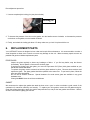
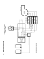
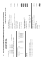
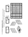
INSTALLATION AND OPERATING INSTRUCTIONS
FOR THE HOTBLAST 1950 EPA WOOD BURNING FURNACE
Verified and tested following CSA
B366.1 M91, UL 391-95, 99 by :
Intertek Testing Services
Distributed by:
UNITED STATES STOVE COMPANY
227, INDUSTRIAL PARK ROAD
P.O. BOX 151
SOUTH PITTSBURG TN 37380
Tel: (423) 837-2100 Fax: (423) 837-2109
Please keep this document
TABLE OF CONTENTS
INTRODUCTION ......................................................................................................................2
1.
CHIMNEY AND DRAFT ....................................................................................................2
2.
SAFETY RULES ...............................................................................................................2
2.1
2.2
2.3
2.4
2.5
2.6
2.6.1
2.7
2.8
3.
3.1
3.2
3.3
3.4
3.5
3.6
3.7
4.
4.1
4.2
4.3
4.3.1
4.3.2
4.3.3
5.
5.1
5.2
5.3
5.4
GENERAL REQUIREMENTS .................................................................................................................... 2
ODOUR FROM THE PAINT....................................................................................................................... 3
ASH DISPOSAL ......................................................................................................................................... 3
CREOSOTE BUILD-UP AND REMOVAL ................................................................................................. 3
SMOKE DETECTOR.................................................................................................................................. 4
DOOR GLASS............................................................................................................................................ 4
GLASS SPECIFICATIONS ........................................................................................................................ 4
ASH DRAWER ........................................................................................................................................... 4
ASH GRATE............................................................................................................................................... 4
APPLIANCE INSTALLATION...........................................................................................5
UNIT LOCATION........................................................................................................................................ 5
CLEARANCES TO COMBUSTIBLE MATERIALS ................................................................................... 5
PIPE CONNECTOR AND DAMPER .......................................................................................................... 6
COMBUSTION AIR .................................................................................................................................... 7
ELECTRICAL CONNECTION.................................................................................................................... 8
THERMOSTAT ........................................................................................................................................... 8
FAN CONTROL.......................................................................................................................................... 8
OPERATING INSTRUCTIONS..........................................................................................9
LIGHTING................................................................................................................................................... 9
PREHEATING ............................................................................................................................................ 9
HEATING.................................................................................................................................................. 10
EARLY SIGNS OF OVERFIRED FURNACE........................................................................................... 10
WOOD AS HEATING FUEL..................................................................................................................... 10
CHIMNEY FIRES...................................................................................................................................... 11
MAINTENANCE ..............................................................................................................12
MAINTENANCE OF THE EXCHANGERS .............................................................................................. 12
CHIMNEY MAINTENANCE...................................................................................................................... 13
MAINTENANCE OF THE BLOWER MOTOR ......................................................................................... 13
DOOR GASKET MAINTENANCE ........................................................................................................... 13
6.
REPLACEMENT PARTS ................................................................................................14
7.
WIRING DIAGRAM .........................................................................................................15
8.
HOTBLAST 1950 TECHNICAL DATA............................................................................16
8.1
8.2
9.
GENERAL TECHNICAL DATA ............................................................................................................... 16
TECHNICAL DATA – ELECTRIC CONNECTION REQUIREMENTS .................................................... 16
DUCTS AND DAMPERS DIMENSIONS (EXAMPLES OF CALCULATION) .................17
10.
HOTBLAST 1950 BRICKS LAYOUT ..........................................................................18
11.
TROUBLE SHOOTING................................................................................................19
1
INTRODUCTION
Take note that this furnace operates like an EPA wood burning stove. This applies to the lighting, the embers and
the minimum combustion air intake which depends on the type and the grade of the combustible.
This model line is certified as meeting the emissions limits in 40 C.F.R. part 60, section 60.532 (B) per EPA
methods 28 and 5G-3, February 1988.
Average emissions rate: 6.56 g/hr
Average heating efficiency: 71.43%
To optimize the efficiency of your furnace, here are few advices you should follow when installing or operating
your Hotblast 1950 furnace.
Respect the local codes (when in doubt, consult your local dealer).
Make sure your furnace is installed according to the instructions on the certification plate.
All controls adjustments must be performed by a qualified technician. The controls settings and the blower speed
must conform to the recommendations of the National Warm Air Heating and Air Conditioning Association and
respect the recommended static pressure ranges in the warm air bonnet of the furnace (see General Technical
Data, static pressure).
1.
CHIMNEY AND DRAFT
This furnace must be connected to a chimney certified for wood burning heating appliances; a 7 inch connector is
highly recommended for your Hotblast 1950.
If draft exceed –0.06 in. W.C a barometric damper should be installed on the smoke pipe.
Never install a manual damper.
The barometric control must be adjusted so that the maximum draft measured at the furnace outlet does not
exceed -0.06 in. w.c. Please note that a draft exceeding -0.06 in. w.c. could produce an uncontrollable fire. On the
other hand, the minimum draft required is -0.04 in. w.c. in the evacuation pipe.
2.
SAFETY RULES
2.1
GENERAL REQUIREMENTS
Make sure the chimney outlet and the pipes are clean and in good condition.
Do not use chemical products or flammable liquids to light the fire.
Do not burn wood coated with paint, glue or chemical products.
Do not burn wastes or flammable liquids such as gasoline, naphtha or motor oil.
Do not install an automatic feeder on this furnace.
Do not store wood in the vicinity of the furnace. Respect the required clearances between combustible materials
and the source of heat.
2
WARNING
-THE ASH DRAWER AND EXCHANGERS ACCESS PANEL GET VERY HOT.
-DO NOT MANIPULATE WITH BARE HANDS.
2.2
ODOUR FROM THE PAINT
It is normal that a smoke odour emanate from the unit when you first light it. It is recommended to burn it at high
rate and ventilate the building until the odour resorbs.
2.3
ASH DISPOSAL
Ashes must be placed in a metal container with a tight fitting lid. The container should be stored outdoors, well
away from combustible materials. If the ashes are meant to be buried in soil, you should wait until all cinders have
thoroughly cooled before burying.
2.4
CREOSOTE BUILD-UP AND REMOVAL
When wood is burned slowly, it produces tar and other organic vapours which, when combined with moisture,
form creosote. The creosote vapours condensate in a relatively cool chimney flue. As a result, creosote residues
accumulate in the flue lining.
N.B.: To minimize the frequency of the chimney cleaning, buy your firewood at least one year before using it. Store
it in a dry place in order to obtain the minimum moisture content and optimize its efficiency. Do not store wood or
combustible materials within the installation minimum clearances or the space required to reload the appliance and
remove the ashes.
When ignited, creosote produces an extremely hot fire inside the chimney.
To avoid chimney fires, it is important to do the turnover of wood. Inspect the chimney and venting system at
regular intervals to determine a cleaning cycle. A weekly cleaning might be required during mild temperature
periods but a monthly cleaning should be sufficient during colder periods. If a significant layer of creosote has
accumulated, it must be removed immediately to eliminate the risk of a chimney fire. Remember that a small
hot fire is preferable to a large smouldering one to prevent creosote build-up within the system. An emergency plan
is necessary in case of a chimney fire. It is recommended to clean the heat exchangers thoroughly at the end of the
season to prevent rust.
3
2.5
SMOKE DETECTOR
We highly recommend the use of a smoke detector. It must be installed at least 15 feet (4,57 m) from the
appliance in order to prevent undue triggering of the detector when reloading.
2.6
DOOR GLASS
To maintain a clean and safe installation, do not build your fire too close to the glass or allow the fire logs to lean
on the glass.
Do not operate your furnace at the minimum rate for prolonged periods and keep the air inlet opened long enough
during the fire start-up to prevent the fire from going out; failure to do so will contribute to the sooting up of the door
glass, exchangers and chimney.
An intense fire will help keeping the glass clean. However, in the event that your glass gets stained, which should
not occur, you will have to clean it using a wet cloth and oven cleaner. The glass may be cleaned ONLY when the
unit has cooled down. Do not use abrasive cleanser. Wood stove glass cleaners are available on the market and
their efficiency makes no doubt.
WARNING: Avoid knocking or scratching the glass which could be damaged.
2.6.1 GLASS SPECIFICATIONS
The glass is made of Pyroceram type of glass, 3/16” – (5 mm) thick.
Do not operate your furnace with a broken glass, as this could seriously damage your appliance.
You can purchase your replacement glass from your Hotblast dealer.
2.7
ASH DRAWER
Your appliance is equipped with an ash drawer to collect ashes produced by the combustion of wood. This
drawer must not be left open during combustion as this will cause over firing and serious damage to the furnace.
The drawer must be cleaned regularly.
It is important that the door and the ash drawer be kept closed while the appliance is in use.
Maintain all gaskets in good condition: in case of deterioration, contact your dealer for
replacement.
2.8
ASH GRATE
You must replace the ash grate if it is damaged and a replacement may be obtained from your dealer. The steel
plate on the ash grid is meant to optimize the heat inside the combustion chamber and should only be removed to
empty the ashes.
4
3.
APPLIANCE INSTALLATION
3.1
UNIT LOCATION
The furnace must be installed where outside air supply is sufficient for proper combustion. In airtight houses, it
might be necessary to install an outside air inlet (see details in section 3.4).
The furnace must be positioned so that the connector is as short as possible; minimize the use of 90o elbows.
The owner must ensure a proper installation to allow a safe operation of the appliance.
3.2
CLEARANCES TO COMBUSTIBLE MATERIALS
N.B. This appliance must be installed according to the instructions on the unit’s certification plate.
MINIMUM CLEARANCES TO COMBUSTIBLE MATERIALS FOR HOTBLAST 1950 FURNACE
N.B. THE SIZE OF THE AIR RETURN CONDUITS SHOULD BE AT LEAST EQUAL TO THE
SIZE OF THE COLD AIR PLENUM OPENING.
5
3.3
PIPE CONNECTOR AND DAMPER
Before proceeding to connection, remove all accessories such as
scraper, shovel and poker from the evacuation pipe of the furnace.
A 7” diameter chimney listed for use with wood burning heating appliances is highly recommended for the
Hotblast 1950. In this case, a reducer from 7” to 6” is required. If draft exceed –0.06 in. W.C a barometric damper
should be installed on the smoke pipe. Never install a manual damper.
REDUCER
DIAMETER 7 "
For a proper installation, follow the advices below:
1. All the joints of the evacuation pipe must be secured, using three screws.
Make sure that each screw goes through the inner walls of both connectors (male and female). See
pictures below showing a male-female coupling.
PROPER INSTALLATION
IMPROPER INSTALLATION
CAUSE RESTRICTION
2. A minimum rise of 1/4 inch per horizontal foot must be respected.
6
DAMPER
The barometric control must be adjusted so that the maximum draft measured at the furnace outlet is limited to 0.06 in. w.c. Please note that a draft higher than -0.06 in. w.c. could result in an uncontrollable fire. On the other
hand, the minimum draft to be respected is -0.04 in. w.c. in the evacuation pipe on the solid fuel side.
3.4
COMBUSTION AIR
In the event that the furnace and the chimney are completely cold, it might be necessary to provide fresh air by
opening a door or a window for a few minutes during the lighting procedure.
Take note that a house constructed or renovated in order to be airtight is liable to lack fresh air necessary for a
proper combustion and operation of flame producing heating appliance.
In such a case, when starting up the fire, do not operate appliances which evacuate air outside the house such
as:
-
Range hood
-
Air exchanger
-
Clothes dryer
-
Bathroom fan
-
Ventilated central vacuum system
NOTE:
It is recommended to install an outside air inlet of minimum 4” diameter in the room where the heating appliance is
installed (see drawing below). To do so, it is preferable to choose a wall that is not exposed to dominant winds,
depending on the conditions surrounding your house.
.B.
The owner of the furnace is responsible for the room salubrity in case of negative pressure or
3.5
ELECTRICAL CONNECTION
The following instructions do not supersede the local code.
HOTBLAST 1950
On the Hotblast 1950 the combined limit control is installed with the support provided on the left side of the
appliance (two holes are predrilled on the edge of the furnace), and connected to the electrical box along with the
transformer. Install the damper motor on the right side of the front facade above the door (use pre-drilled holes).
The chain that links the air inlet latch to the motor must have a play of 1/8 in. When there is no call for heat, the air
inlet latch must be completely shut and the chain must be affixed to the damper motor at the “8 o’clock” position. *
WARNING: USE WIRES SUITABLE FOR 75O C (167 O F) ONLY.
* (With all reserves on the minimum combustion air to be increased depending on the type and quality of the
combustible).
3.6
THERMOSTAT
The thermostat must be installed on an inside wall in a location where it is not likely to be affected by the draft
coming from an air outlet. It must be installed at a minimum of 55 inches above the floor.
3.7
FAN CONTROL
The fan control setting may vary depending on the type of installation; the “fan OFF” temperature is preset at
110o F and the “fan ON” at 150° F at the factory. This setting should provide a proper operation for most
installations.
For a prolonged operation of the blower, it is preferable that the “fan OFF” setting be low enough. But a “fan OFF”
setting too low will cause undesirable cold air circulation. To modify the setting, move the tab on the temperature
dial of the fan limit control at the desired position.
The adjustment of all controls must be performed by a qualified technician. The controls setting and the blower
speed must conform to the recommendations of the “Warm Air Heating and Air Conditioning National Association”.
To obtain a continuous air circulation during summer, move the manual switch ON.
8
4.
OPERATING INSTRUCTIONS
Control system
On the wood only furnaces , the thermostat controls the air inlet damper. When the thermostat calls for heat, the
damper opens and the fire burns up. When the furnace gets hot enough, the combined limit control activates the
blower motor at the speed selected for wood heating.
The chain that links the air inlet damper to the motor must have a play of 1/8 inch. When there is no call for heat,
the air inlet damper must be completely closed and the chain must be affixed to the servo-motor at the “8 o’clock”
position. *
* (With all reserve on the minimum air to be increased depending on the type and quality of the combustible).
4.1
LIGHTING
1. Open the door
Note: In the case that there is a bed of coals in the bottom of the furnace, go to step b) Pre-heating.
2. Remove the steel plate on the ash grid and dump the ashes in the ash drawer.
3. Put the steel plate back in place, making sure it is properly seated. The steel plate on the ash grid is intended to
optimize the heat retention into the combustion chamber.
4. Place one or two dry kindlings at the front of the combustion chamber.
5. Place newspaper strips on top of the kindlings.
6. Cover the newspaper with more kindlings and small pieces of dry wood.
7. Add newspaper strips, then light the fire as low as possible and leave the door 1/2" (13 mm) opened. If lighting
fails , you might experience a back draft through the air inlets.
4.2
PREHEATING
1. Once the kindling is well ignited or the coals revived, put 2 or 3 fire logs in such a way that the flames can
interlace between the logs then close the door. It is important to respect these loading sequences so that the
wood burns from the front to the back of the furnace.
2. Wait 15 to 20 minutes, then proceed with loading the furnace.
9
4.3
HEATING
1. When loading the furnace, spread the coal and embers evenly in the center of the combustion chamber before
adding new logs.
2. Do not overload. Air must circulate freely in the upper part of the combustion chamber in order to obtain an
efficient operation of the appliance. Please note that a small hot fire will produce much less residues than a large
smouldering one.
IMPORTANT: DURING THE HEATING PROCESS, REMOVE THE ASHES AND WOOD THAT COULD
OBSTRUCT THE 1/4" (6.4 mm) HOLE LOCATED BELOW THE DOOR INSIDE THE FURNACE.
PROCEDURE TO OPEN THE LOADING DOOR
TO MINIMIZE THE RISK OF SMOKE SPILLAGE, OPEN THE DOOR 1”
AND WAIT ABOUT 10 SECONDS BEFORE OPENING COMPLETELY.
THE PURPOSE IS TO STABILIZE THE PRESSURE INSIDE THE FURNACE.
4.3.1 EARLY SIGNS OF OVERFIRED FURNACE
1. Roaring fire.
2. Chimney connector is glowing red.
3. Extreme heat coming from the furnace.
4. If this occurs, DO NOT OPEN THE DOOR, shut-off the air inlet opening completely, and wait until the glow has
completely subsided.
ALWAYS KEEP THE DOOR AND THE ASH DRAWER CLOSED
(except for lighting and maintenance).
4.3.2 WOOD AS HEATING FUEL
We recommend that you burn seasoned hardwood only.
There are two important factors to be considered when choosing a type of wood: the moisture content and the
wood density. Dry hardwood, such as maple, oak and beech will provide better results because of the high density
and minimal tar produced during combustion. It is highly recommended to use wood that has been dried at least six
months. Do not use coal as heating fuel in this appliance.
10
Whenever a high amount of smoke is noticed in the room, you must:
1. Open doors and windows.
2. Make sure the furnace door is closed as well as the damper (if necessary, lower the thermostat starting point or
undo the chain of the damper and close the barometric draft control manually).
3. When the furnace has cooled down, inspect the chimney to detect obstructions and consult a specialist to
determine the cause of the smoke spillage.
CARBON MONOXYDE IS A LETHAL GAS (ODOURLESS AND COLOURLESS), WHICH YOU MUST
BEWARE OF.
4.3.3 CHIMNEY FIRES
They might occur when the fire gets extremely hot; burning paper, cardboard, branches or small pieces of wood
can ignite the creosote residues accumulated in the evacuation flue system. The usual signs are:
1. Rumbling
2. The flue gets extremely hot
3. Sparks are coming out of the chimney
In case of a chimney fire, call your local fire department immediately and sprinkle the
roof around the chimney with water.
Make sure that the furnace door is closed as well as the damper (if necessary, lower the thermostat starting point
or release the chain from the damper and CLOSE the barometric draft control manually).
If the fire gets uncontrollable due to improper use or because the draft is too strong, follow the same procedure
as in a chimney fire except that you will have to OPEN the barometric draft control manually.
LOCAL FIRE DEPARTMENT.
Phone number: ___________________________________
11
5.
MAINTENANCE
5.1
MAINTENANCE OF THE EXCHANGERS
The evacuation pipe and the exchangers should be inspected regularly during the burning season. Easy access
is provided (without the use of tools): unscrew the wing nut on the exchangers access door. See pictures below.
Wing nut
Insulation
pad
Exchangers cover
Before cleaning the three exchanger pipes, move the upper plate of the combustion chamber forward. Using the
scraper, clean the three exchanger pipes. The accumulated dirt in the lateral exchangers will fall into the
combustion chamber; the dirt in the central exchanger will have to be removed from the front or the back of the
furnace. After cleaning the exchangers, make sure that the upper plate is free of ashes and do not forget to push
the upper plate back to its original position. Finally, close the exchanger access door.
HOTBLAST 1950
SECTION VIEW
12
5.2
CHIMNEY MAINTENANCE
One of the most efficient methods is to sweep the chimney is using a hard brush. Brush the chimney downward
so soot and creosote residues will come off the inside surface and fall at the bottom of the chimney where it can be
removed easily.
The chimney must be checked regularly and if creosote has accumulated, it must be removed without delay.
Cleaning on a monthly basis should be sufficient during the coldest months.
Smoke flue inspection
5.3
-
The smoke flue should be inspected regularly during the heating season.
-
If possible, the smoke flue should be dismantled and cleaned.
-
The flue should be inspected to detect any damage.
-
If no damage is noticed, put the flue back in place; otherwise, it must be replaced.
-
Use only wood as a combustible.
-
Seasoned hard wood logs 18” to 22” long are recommended as a combustible.
MAINTENANCE OF THE BLOWER MOTOR
The two bearings of the motor must be lubricated once a year using non detergent SAE 20 oil.
DO NOT OVERLUBRICATE
FILTERS
The blower must not be operated without the filters. In order to operate a slow combustion heating system
efficiently and safely, you have to ensure regular maintenance. This means that the chimney, the joints and the flue
must be kept in good condition and the air filters must be cleaned or replaced regularly. Use the same size and
same type as the original filters.
Filters dimensions
Filters 12” x 24” (HOTBLAST 1950 part number 53-005-035)
5.4
DOOR GASKET MAINTENANCE
It is important to maintain the door gasket in good condition.
adjustment may be then required.
13
After a while, the gasket might sag; a door
Door adjustment procedure:
1. Unscrew completely the locking pin (see picture below).
Locking pin
2. To increase the pressure of the door on the gasket, turn the handle counter clockwise; to decrease the pressure
on the door on the gasket, turn the handle clockwise.
3. Finally, screw back the locking pin about 1/4” deep, make sure you lock it in place with the nut.
6.
REPLACEMENT PARTS
Your HOTBLAST furnace is designed to burn clean and require little maintenance. It’s recommended to conduct a
visual inspection at least once a month to uncover any damage on the unit. Make necessary repairs as soon as
possible with genuine Hotblast replacement parts.
DOOR GLASS
•
•
•
•
•
Inspect the glass regularly to detect any breakage or failure. If you find any defect, stop the furnace
immediately. Never operate a furnace with a broken glass.
If you have to change your door glass, you must use Pyroceram 3/16”(5mm) thick glass available at your
HOTBLAST authorized dealer.
To replace the glass, remove screws that hold the glass retainers in place. Remove these retainers and
replace the glass. The glass gasket should be replaced at the same time. To put back in place, follow the
same procedure backwards.
Do not use an abrasive cleanser. Special cleansers for wood stoves glass are available in any good
hardware store.
Clean glass ONLY when the unit has cooled down.
GASKET
We recommend to replace the gasket that seals the door once a year, in order to maintain a good control of the
combustion for maximum efficiency and security. To replace your door gasket, remove the old gasket and glue.
Clean the surface thoroughly, apply glue sold for that particular use, and put the new gasket onto the door. Wait for
at least 2 hours before lighting your furnace.
14
REVISION JUNE 17TH 2005
OFF
ON
1
2
3
BLACK
BLUE
120 V.A.C.
24 V.A.C.
TRANSFORMER
BLACK
JUNCTION BOX
WHITE
SERVO-MOTOR
24 V.A.C.
BLACK
THERMOSTAT
24 V.A.C.
WHITE
SWITCH
15
OFF 110°F
ON 150°F
LOAD LIMIT 250°F
LIMIT
LOW HIGH LINE
LINE
FAN
HONEYWELL
L6064
HOTBLAST 1950 WOOD
DIRECT DRIVE
MOVE THIS WIRE
TO CHANGE
MOTOR SPEED
RED
WIRING DIAGRAM
BLUE
RED
7.
BLACK TRANSFO
BLACK
WHITE
COMMUN
LOW
MED LOW
MED HIGH
HIGH
THERMINAL
BOARD
L2
120 V.A.C.
L1
4 SPEED
MOTOR
BLOWER
8.
HOTBLAST 1950 TECHNICAL DATA
HOTBLAST
1950
47”
A
B
C
D
E
F
G
25 ½”
47 ¼”
15 ⅞”
28”
24 ½”
FLUE
44”
* 7”
WEIGHT
560
* Reducer required
8.1
GENERAL TECHNICAL DATA
MODEL
DIRECT DRIVE
FAN
MOTOR
SPEED
OUTPUT
TEMP
VAR.
(CFM)
( F)
O
BTU/ HR
STATIC PRESSURE
(WOOD)
MIN.
FILTER
MAX.
(2)
0,6
12” x 24” X 1”
H2O
HOTBLAST 1950
8.2
MODEL
WOOD
DD-10
1/3
3 or 4
1300
78
140000
0,2
TECHNICAL DATA – ELECTRIC CONNECTION REQUIREMENTS
OUTPUT
(CFM)
TEMP. VAR.
O
( F)
BTU/HR
AMPS
TOTAL
15
BREAKER
REQUIRED
16
FEEDER
GAUGE
VOLTAGE
SINGLE PHASE
120
ELEMENTS
QTY
reduce by 2”
reduce by 3”
5 inch outlet
6 inch outlet
Always by 8” thick
10’
10’
5”
6”
Max 6,000 Btu
Max 7,000 Btu
1 x 90o
1 x 90o
1 x 90
Max 4,000 Btu
Average equivalence
o
Elbow
For a 6” warm air outlet: 2” x 14” damper or 4” x 12”
For a 5” warm air outlet: 2” x 12” damper or 4” x 10”
For a 4” warm air outlet: 2” x 10” damper
DAMPER
10’
Length
4”
Dimensions
Ducts specifications (heat)
N.B.: The main duct must be reduced every 2 outlets.
reduce by 1”
4 inch outlet
SIMPLIFIED METHOD
DISTRIBUTION SYSTEM
17
3 x 4 x 60
Windows:
12 + 12 x 8: 192 x 22:
Exposed walls:
12 x 12 x 8: 1,152 cu. ft. x 1.8 Ch. air/hr:
BEDROOM (for example: 12 x 12)
7,018 Btu
720 Btu
4,224 Btu
2,074 Btu
60,840 Btu
or 54 Btu per sq. ft.
TO BE ADDED:House 1 1/2 floor = 25%
House 2 floors
= 40%
7,906 Btu
52,904 Btu
4,200 Btu
8,640 Btu
23,936 Btu
16,128 Btu
Non-insulated basement: 25%
Insulated basement: 15%
2 x 3 x 7: 42 x 100:
Number of doors:
12 of 3 x 4: 144 x 60:
Number of windows:
40 + 40 + 28 + 28: 136 x 8: 1,088 cu. ft. x 22:
Exposed walls:
28 x 40 x 8: 8,960 cu. ft. x 1.8 Ch. air/hr:
HOUSE DIMENSIONS
Example: 28 x 40 bungalow: 1,120 sq. ft.
WARM AIR SYSTEM INSTALLATION
DUCTS AND DAMPERS DIMENSIONS (EXAMPLES OF CALCULATION)
Ducts size (heat)
9.
4 1/2"
4
1
7
9
7
7
6
7
7
5 1/2"
3
5
8
7
6
9
9"
6
2
6
9
2
3 1/2"
8
7
7
7
7
7
9
7
7
7
7
7
7
7
7
7
6
6"
6
9
8
9"
18
DESCRIPTION
7 1/2"
1
9
8
7
BRICK 4 1/2" X 9" SPECIAL
BRICK 4" X 9" SPECIAL
BRICK 4 1/2" X 9"
BRICK 4" X 9"
BRICK 4 1/2" X 8 3/4"
5
BRICK 4 1/4" X 7 5/8"
BRICK 4 1/2" X 7 5/8"
ASHGRATE
6
1 1/2"
3"
4
2
20
6
1
1
1
2
1
QTY
1 1/4"
BRICK 4 1/4" X 9" SPECIAL
4 1/4"
9"
4
3
2
1
ITEM PART #
3"
1 5/8"
4"
PUTTING BRICKS UP IN THE COMBUSTION CHAMBER
WARNING: INSTALL THE CERAMIC BLANKET PANEL BEFORE
10. HOTBLAST 1950 BRICKS LAYOUT
11. TROUBLE SHOOTING
PROBLEM
CAUSES
SOLUTIONS
Heating inefficient during the first
combustions. Lack of draft.
Improper adjustment of the
barometric damper (opened too
wide). Chimney flue restriction (too
long., or too many 90o elbows)
Adjust the damper, minimize the
chimney length and use 45o elbows.
Furnace heats well, warm air plenum
is very hot by there is not much heat
coming out in the room.
Improper installation of the ducts,
little static pressure, unbalanced
system (too many warm air outlets
and not enough cold air inlets).
Reinstall the ducts correctly.
Respect the minimum static pressure
of 0.20 in. w.c.
Furnace consumes a lot of wood.
The thermostat which controls the
damper is continuously activated or
is too close to a source of cold air.
Damper not properly adjusted.
House not insulated enough. Ash
drawer is not tightly closed. Furnace
too small for the surface to be
heated. Unbalanced ventilation
system, very little heat where the
thermostat is located.
Relocate the thermostat. Adjust the
chain that links the damper to the
damper motor. Rebalance the
ventilation system in order to
increase the air flow in the room
where the thermostat is located.
Fan start-up is too slow.
Fan “ON” setting too high. Return air
is too cold (temperature lower than
65 degrees). Limit control not well
located in the warm air plenum.
Lower the temperature starting point.
The “fan ON” setting on limit control
is set at 150°F, it may reduced in
some particular installations. Reduce
the fresh air flow. Relocate the limit
control.
A lot of creosote, moderate heat
output.
Wet wood, lack of draft. Barometric
damper not properly adjusted. Dirty
chimney.
Use dry wood. Adjust the barometric
damper. Clean the chimney flue and
the furnace exchangers.
Furnace heats a lot but the warm air
plenum does not get hot.
Wet wood or low grade wood. Too
much cold air return for the hot air
ducts. Unbalanced ventilation
system. Blower speed too high
Use dry wood. Reinstall the
ventilation system correctly. Use a
lower blower speed.
IMPORTANT NOTE
FOR, INSTALLATION OF A CENTRAL HEATING VENTILATION SYSTEM, IT IS HIGHLY
RECOMMENDED TO CONSULT A HEATING SYSTEM VENTILATION SPECIALIST.
N.B.: UNITED STATES STOVE COMPANY IS NOT RESPONSIBLE FOR POOR APPLIANCE
PERFORMANCES, DUE TO AN IMPROPER INSTALLATION.
19