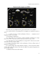
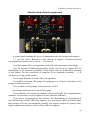
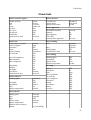
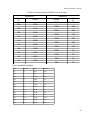
1
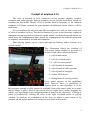
Ilyushin IL-14-P
Passenger modification with
32 seats and ASh-82T engines
Model for X-Plane 9.30
User's manual
1
Table of contents
Short-story description of airplane.......................................................................................................3
Contacts and gratitudes.........................................................................................................................3
Installing the model, work with the plugin...........................................................................................4
Cockpit of airplane Il-14......................................................................................................................5
Buttons for the call of panels...........................................................................................................6
General view of flight deck.............................................................................................................7
Explains of panels and devices ............................................................................................................8
Main panel (menu)...........................................................................................................................8
Control panel (service menu)...........................................................................................................8
Payload panel...................................................................................................................................9
Fight captain's panel......................................................................................................................10
Artificial horizon AGK-47.............................................................................................................12
Aviation clock ACHS-1.................................................................................................................13
First flight officer's panel...............................................................................................................14
Central panel..................................................................................................................................15
Panel of autopilot...........................................................................................................................16
Pilot's overhead panel....................................................................................................................17
Panel of radio-compass set ARK-9................................................................................................19
Central stand of pilots (upper part)................................................................................................20
Central stand (underbody).............................................................................................................21
Panel of navigator..........................................................................................................................22
Panel of radio operator...................................................................................................................23
General information about an airplane...............................................................................................24
Geometrical information................................................................................................................24
Weight information........................................................................................................................24
Flying characteristics.....................................................................................................................25
Speed limitations............................................................................................................................26
Flying limitations...........................................................................................................................26
Minimum required length of RUNWAY........................................................................................27
Limitations of systems...................................................................................................................27
Modes of engines...........................................................................................................................27
Procedures..........................................................................................................................................28
Pre-flight preparation.....................................................................................................................28
Start and warming up of engines..................................................................................................30
Taxiing...........................................................................................................................................32
Take off and climb.........................................................................................................................32
En-route flight................................................................................................................................33
Descend..........................................................................................................................................34
Landing..........................................................................................................................................35
Turning off the airplane.................................................................................................................37
Special cases on flight........................................................................................................................39
Engine failures...............................................................................................................................39
Landing gear fail............................................................................................................................41
Fail or detachment of flaps............................................................................................................41
Check-lists..........................................................................................................................................42
Short reference of units......................................................................................................................43
2
Short-story description of airplane
Short-story description of airplane
Thank you for purchasing new model Il-14 for X-plane9.30
The airplane of Il-14 was projected in 1946-52 as development of airplane Il-12,
called to replace a Li2 on air-routes, out-of-date by that time. Creation of new model
is conditioned the necessity of increase of reliability, and by the increase of distance
of flight. For subsequent 30 years the airplanes of Il-14 made the considerable epoch
of distant transportation, creations of new air-routes and mastering of arctic territories
of Earth. This model is called to recreate and historically reproduce this known
airplane.
The package of Il-14 contains the detailed three-dimensional model of airplane
with the complete reproducing of all movable parts and their possible absence; close
to the real physical model of airplane with the recreation of many distinctive
descriptions of the real prototype. In a cockpit all devices and systems are recreated
with inherent them original logic of work and refuses. Most management organs
accessible from a three-dimensional virtual cockpit, and some panels are doubled as
pop-up flat windows.
Although in this model some retreats are possible from reality, author
recommends to familiarize with real POH of airplane Il-14.
Contacts and gratitudes
Model author, devices and logic is Andrey Kozyaruk (Felis)
e-mail: [email protected]
An author of the module of user avionics is Alexander Babichev (Asso)
Model's author expresses the gratitude to Mel'nikov Alexander Evgenievich —
author of site of http://aviaros.narod.ru/avio.htm for given photos; To Yuriy (Omega)
and Vladislaw Blindin for technical consultation.
Special gratitude of Rubcov Nikolay Aphanasievich, for testing model and
technical consultation.
Nikolay Aphanasievich is former captain of Il-14 from the beginning of its
exploitation to 1986 year, working in governmental detachment, after at the Perms
airmotor factory. In post-war years provided the air special delivery of cabinet of
ministry on the USSR. Deserved veteran of Aeroflot.
Long years to you and salubrity!
3
Installing the model, work with the plugin
Installing the model, work with the plugin
At the purchase of model on the site of http://store.x-plane.su/ you got the archive
of «Il-14_930_ENG.zip». To install model in a simulator, you are enough to unzip an
archive in a catalog with other models, related to the general airplanes. For example:
X-plane 9.30\aircraft\general Aviation.
This model contains the plugin - module of custom avionics for rendering
devices and treatment of their logic. The feature of this module consists in that to
install it in a general catalog for the plugins in simulator NOT REQUIRED. At
opening a model in a simulator — the module is loaded automatically and unloads at
the open of other airplane.
The module of custom avionics constantly develops and you can find its updates
on the site http://code.google.com/p/sasl/ under the name XAP. For replacement of the
module it is necessary to delete or carry elsewhere content of catalog of
Il-14_930\plugins and replace with new files, taken from this site.
Module of custom avionics, and all devices and logic are open and free. It means
that you quite freely can use these components in the aims, to change and integrate in
the projects on condition of maintainance of authorship. With questions for licensing
it is necessary to contact to the authors (see this higher).
As already talked higher, the module is started at opening a model in a simulator.
However during making alteration there is not a necessity to reopen a model while
coding of devices. The module reacts on the hotkey of F8, pressing of which will reinitialize the module. It should be remembered that any errors in a code can result in
unforeseeable consequences, and that is why if an user will decide to change
something in-process devices he does it on his fear and risk. Authors carry no
responsibility for possible harm, brought in the case of bringing of the changes by
user in the source code of the module, devices or logic.
However an user always can appeal for a help by the addresses indicated higher.
4
Cockpit of airplane Il-14
Cockpit of airplane Il-14
The crew of airplane of Il-14 consisted of four persons: captain, co-pilot,
navigator and radio operator. Each of members of crew had the workplace, which are
recreated in this model. Model of Il-14, besides built-in functions, to the inherent
airplanes in X-plane, contains the great number of additional, about which it will be
said below.
As in a simulator by only one man flies an airplane as a rule, he has to play role
of each of members of crew. For the facilitation of access to the necessary organs of
management pop-up panels are foreseen in this model. On them the special menus are
taken away for a management these panels, by a management the external equipment
of airplane, calculation of its load and centration.
Most pop-up panels can be caused through the hotkeys and/or buttons in a
virtual cockpit.
This illustration shows the location of
click-zones (areas sensible to pressure) of
mouse for the call to often used panels.
1 - call of main menu
2 - call of overhead panel
3, 4 - call of central panels
5 - call of panel of navigator
6 - call of panel of radio operator
7 - call of panel of autopilot
8 - a show GPS device
9 - hiding/show of steering wheels
Every panel appears in the predefined
place, however there is possibility to
dispose them at own discretion. It is for
this purpose enough to click mouse in available from click-zones space on a panel
and to «drag» a panel. There is the special area in a right lower corner, dragging for
which, you can change a size and proportions of panel on the discretion. Closing of
panel is produced by clicking the cross in the right overhead corner of pop-up
window, by pressure of combination of the keys on which a panel reacts or by
pressure on the proper button in a cockpit or on a panel with a menu.
5
Cockpit of airplane Il-14
Buttons for the call of panels
Shift + F2 is a main menu of management panels and ground power
Shift + F3 is a panel of calculation of fuel, commercial load and centration
Shift + F4 is an overhead panel of pilots
Shift + F5 is overhead part of central panel
Shift + F6 is an lower of central panel
Shift + F7 is a panel of radio operator
Shift + F8 is a panel of navigator
Shift + F9 is a panel of autopilot
6
Cockpit of airplane Il-14
General view of flight deck
On the picture rotined higher the location of basic panels of pilots and their
division is represented on functionality:
1 is an overhead panel of pilots. Doubled by flat panel.
2 is a panel of captain of airplane
3 is a middle panel of pilots. Aviation clock and magnetic compass
4 is a panel of co-pilot
5 is overhead part of central panel. Doubled by flat panel.
6 is an underbody of central panel. Doubled by flat panel.
After the backs of pilots, the workplaces of navigator and radio operator are
located. At a desire you can glance there in a simulator — they are functional.
More detailed description of panels and devices see is in the next chapters of this
guidance.
7
Explains of panels and devices
Explains of panels and devices
Main panel (menu)
The main menu of airplane is
executed in a semilucent kind, that an user
was in a position to work with it and see
the applied changes. On a main panel the
call of all panels of airplane Il-14 buttons
are located, including the menu of loading
and service. Here is possibility to
show/hide steering wheels and GPS device
in a virtual cockpit.
As the real airplane was not
completed with similar device — in this
model it is hidden by default.
The button of query of ground power
is located in a right lower corner. In the
case of availability — a ground power is
connected for a few seconds and button changes a color from red to green.
Control panel (service menu)
A service panel is executed semilucent.
Here is possibility to open or close
practically all opened parts of airplane,
including hoods, skirts, hatches and doors.
On this panel there are the buttons for
covering of engines and Pitots, settings of
brake heels under the wheels of
undercarriage.
In a right lower corner there is the button
for rapid preparation of airplane to flight,
pressure on which forces the closure of all
hatches and uncover the engines and
Pitots.
8
Explains of panels and devices
Payload panel
The panel of load of airplane logically parts on two parts: calculation of fuel and
determination of load and centration.
For determination of necessary fuel for flight, user must enter in cells under a
left chart distance between air-ports, estimate speed of wind enroute, desired speed of
flight and stocked fuels over a calculation. The input of values is produced by
pressing a mouse on the left and on the right from number, by pressing on the left will
decrease the number, on the right — will increase. Speed of wind (longitudinal
constituent) is specified relative course of flight. Positive values are the following
wind, subzero — meeting.
Stocked fuel determined from the calculation of expense of engines on earth,
including warming up and taxiing (160 l/h on both engines, but no more than 80
liters) and navigation supply (550 l/h on two engines, but no less than 55 liters.)
For determination of load and centration the right chart of panel is used. Here
user must enter the amount of passengers on rows in a salon, load of luggage racks,
use of cloak-room in winter time (the number of passengers will be represented),
including weight of buffet air steward and amount of members of crew. Pay regard to
9
Explains of panels and devices
6th line chart: it is used only in the case of the complete filling of salon.
The result of calculation is an amount of fuel in litres, flight mass in kilograms
and centration of airplane in % of MAC (mean aerodynamic chord ). Crossing of red
lines on a nomogram corresponds a load and centration of airplane taking into
account a fuel, dark blue — without an account (supposed load at landing after
making of fuel).
It should be remembered that too backward or the too forward position of
centerf of gravity of airplane results in worsening of its control and flying
descriptions. The optimum is consider a centration 16-19% MAC.
After completion of calculations it is necessary to press on sign «Load an
airplane», wich will record the results of calculations in a simulator and load the
model.
Note should be taken, that a load «by default» for this model is load, proper the
empty equipped airplane with a crew, air steward, and by some supply of food stuffs
in a buffet. In fuel tanks here is the only unproduced remain of fuel.
Fight captain's panel
Flight captain's panel — first that you see after the load of airplane and basic
work of pilot in a simulator is conducted exactly here.
Using and metages devices of this panel:
1 is pressure in a hydraulic accumulator, kg/sm2
10
Explains of panels and devices
2 is pressure in the brake system of the left and right contour, kg/sm2
3 is total pressure in the hydraulic system, kg/sm2
4 is a pointer of course. A device is related to the gyro-compass of airplane and
is in a position of turn of scale for comfort of counting out of courses in relation to
the turn of map.
5 is the button «lamp test». Pressing will lit all lamps in a cockpit for the
exposure of out-of-commission. In this model the refuses of lamps in a cockpit are
not foreseen, but this button will help to define the presence of power in a plane's
network.
6 is a pointer of air speed. Testimonies in tens km/h
7 is a barometric altitude indicator. Two pointers shows an altitude in hundreds
of meters (large) and in thousands (little) in relation to the set pressure in mm.Hg.
Pressure is set by rotary knob at the bottom of device. A little three-cornered pointer
after a scale is intended for calibration the device at the plant.
8 — combined indicator of turn and sliding.
9 — lights of signaling of flight over markers. Green — outer, yellow —
middle, red is inner. After flight middle (inner, at presence of his in air-port) it is
necessary to make decision about landing or go around.
10 — indicators of fire are in engines.
11 — combined artificial horizon, indicator of turn and sliding AGK-47.
Description of device see below.
12 — pointer of rate (variometer) of climb, m/s
13 — indicator of position of wing flaps. Overhead position of pointer —
retracted, lower — extended. Degrees of rejection.
14 — pointer of the landing system on the ILS - PSP-48. A vertical slat shows
the off-course of airplane, horizontal is deviation from glide slope. Two lights under a
device signal maximum rejection and direction for a return on a course. White flags
indicates about absence of signals.
15 — gyro half compas. A device is related to the gyro-compass and has rotary
knob for fine tune.
16 — combined pointer of giro- and radio compass #1. An external scale is
intended for counting out of bearings, internal — related to the gyro-compass and
serves for counting out of course corners. A yellow pointer specifies sending to the
beacon station at presence of signal from it (in the case of no-signal — a pointer
moves chaotically, following by noises in an atmosphere, at the turned off receiver of
radio compass — stops beating in the last position). A double white pointer is
11
Explains of panels and devices
revolved by knob on the left-below of a device and serves for setting of course of
flight or landing.
17 — pointer of radio compass #2. A needle is specified by bearing on the
wireless station.
18 — radio-altitude indicator. For power ON this device the turning button
serves on the left down (the “ON” sign turned to horizontal position). A device is able
to count off a height above a terrain or water under aircraft within the limits of 0 1200m or 0 — 120m. Switching of ranges is the overhead right turning button.
19, 20 — indicators of remain of fuel in the right and left group of tanks
accordingly. An indication is in liters, limit of measuring of 1600l. lights under
devices signal remain of fuel less than 200l in the proper group.
21 — lamp-indicator of marker receiver. Catches fire at flight above any marker.
A sound signal is thus included (bell)
Artificial horizon AGK-47
The combined device of AGK-47 consists of:
1 is rotary knob of zero-adjusting horizon
2 is the button of arrest
3 is an airplane-indicator spatial position of
airplane. An indication is straight. The roll of
aircraft is represented by the turn of airplane in
relation to a zero, pitch — by vertical motion. A
right roll is a right turn, left — left. Raising of
nose of airplane — an indicator rises, lowering
— goes down
4 is an indicator of turn of airplane
5 is an indicator of sliding of airplane
6 is a flag of the arrest system.
For work with device, there must be a power in the electric system of airplane, and
on the overhead panel of pilots tumbler of power of device is turned ON. Pressing the
button of arrest results in setting of indicator in a zero position regardless of position
of airplane. Attention: to arrest only in horizontal flight. After an arrest it is needed to
push the button of arrest once again — a small flag will disappear and a device will
be ready to work. An error can appear in the process of work in the testimonies of
device, for the removal of which it is needed to conduct an arrest repeatedly. In loss
12
Explains of panels and devices
of power a device is heaped up.
Aviation clock ACHS-1
An aviation clock is intended for the
reflection of current time (UTC), counting out
of block and measuring of small intervals of
time.
1 is the button of starting of counting out of
block hours. First pressure — a timer is started,
second — stops, third — throws down in a zero.
2 is the button of starting of stop-watch.
Works like the button 1
3 is the large scale-reading time. Pointers:
hours, minutes, seconds
4 is a little scale for counting out of block
hours. Pointers: hours, minutes. A small flag in a center symbolizes work. Red — a
timer is started, red/white — a timer is halted, white — a timer is downfaulted in a
zero.
5 is a little scale of stop-watch. Pointers: minutes, seconds
In a sunset-to-sunrise a clock illuminate from beneath a green color — scales
and pointers have phosphoric coverage.
13
Explains of panels and devices
First flight officer's panel
Most devices on the panel of co-pilot like the devices of captain.
1, 2 are pointers of radio compass 1 and 2 according
3 is pressure of oil on an exit from engines, kg/sm2
4 is a temperature of oil on included in engines
5 is a temperature of oil on an output
6 is Lamp-Warner of flight of marker
7 is the button for the check of lamps work
8 is an indicator of landing of PSP-48.
9 is gyro half compass
10 is combined artificial horizon AGK-47
11 is a variometer
12 is a air speed indicator
13 is a barometric altitude indicator
14 are indicators of position of landing gears. Pointers above — an gears is
retracted, down — an gears is extended. Under devices there are signaling lamps.
14
Explains of panels and devices
Red — a landing gears is retracted, yellow – the gears in intermediate position, green
— gears are extended.
15 are indicators of flight over outer, middle and inner markers
16 is an indicator of temperature of outward air in a range from — 50 to +150
degrees of Celsius.
17 are indicators of position of skirts of hoods of engines. Pointers upwards —
skirts are fully closed, downward — fully opened.
Central panel
1 is a magnetic compass
2 are indicators of pressure in the pumps
of serve of alcohol of the system of
heating
3 is an aviation clock ACHS-1
4 is a control an autopilot panel. More
detailed work with an autopilot is
described below.
5 is a two-pointer tachometer of engine.
6 is an indicator of manifold pressure of
engines.
7 is a temperature of cylinders of the first
star of engines
8 is a temperature of cylinders of the
second star of engines
9 is pressure of fuel on included in
engines
10 is pressure of oil on included in
engines
15
Explains of panels and devices
Panel of autopilot
The airplane Il-14P is equipped an autopilot AP-45, to working on three
channels. An autopilot is able to retain a permanent course, roll and pitch of airplane
long time without intervention from a pilot. The panel of autopilot parts on two parts:
management to on-course and according to the spatial regulations of airplane.
1 is knob of correction of gyro-compass of autopilot.
2 is knob of choice course of flight. L is a turn to the left, R is a turn to the right.
3 is knob of setting the pitch of flight. D is descend, C — climb
4 is knob of setting the roll of flight
5 is a scale of choice of course. you will pay attention, that a course is specified
by a mark 0, as this device is based on relative deviations from initial position.
6 is a scale of gyro half compass.
7 is a marker of settings of roll
8 is an indicator of current roll of airplane
9 is a marker of setting of pitch. A dark blue area is pitch up, black is down. A
scale is marked through 10 degrees.
10 is an indicator of current position of airplane. Work of him is analogical work
with artificial horizon.
For work with an autopilot:
1. Before its switching ON you need to combine the markers of course (to set
a scale in a zero), roll and pitch according to the current condition of airplane.
16
Explains of panels and devices
2. Turn right both faucets on the lower panel of central stand of pilots.
3. On wing to manipulate pens «turn» for the correction of course, «pitch» for a
set, climb and descend and «roll» for manoeuvres.
For implementation of maneuver through the autopilot of AP45 it is needed to
choose the desired roll and since an airplane will bend over — to revolve the handle
of choice of course to setting of marker 0 on a necessary course. At to approaching to
the necessary course — fluently to clean a roll. It is necessary to take into account
that the autopilot of AP45 is retained by a course through the rudder, and that is why
appearance of sliding of airplane is some time possible.
Pilot's overhead panel
On an overhead panel followings switches and devices is located:
1, 2 are sets of radio compass 1 and 2 accordingly. More detailed than see below.
3 — set of frequency of landing of Nav1
4 is switches of extend/retract of landing lights
5 are switches of landing lights
6 is a switch of taxi light
7 are switches of heating of Pitots
8 are switches of artificial horizons
9 a switch of gyro half compass
17
Explains of panels and devices
10 is a switch of heating propellers
11 are lamps of control of heating of propellers and wings.
12 — a switch of TP-156 is a basic switch of device panel.
13 is a switch of heating of wings
14 are switches of start of engines. Overhead position starts left, lower — right.
Midposition — neutral.
15 is a switch of starters. It is necessary to turn ON for the start of engines.
16 are switches magneto of engines. Lower position is a magneto turned off,
aside is a magneto turned ON. Intermediate positions connects only one from two
magneto. Areas for mouse-click is out of the limits of white circle on his perimeter.
17 is tumbler of switching of power, closed by a red lid. For opening of lid it is
needed to click a mouse on the right from it. Overhead position is
connect the accumulator, middle — it is turned off, lower connects a
ground power supply to the plane's network. As a capacity of storage
battery is small, during the protracted work in a cockpit on earth it is
recommended to connect a ground power (main panel). The start of
engines is recommended from a ground power, batteries are used only
in extreme cases.
18 is a switch of light board to «fasten straps» in a salon
19 is a switch of heating windows
20, 21, 22 are switches of external navigation lights. Red beacon on a tail, red
and green lights and strobes on wings.
23 are switchers of primers of fuel in an engine. It is recommended to turn on
before a start.
18
Explains of panels and devices
Panel of radio-compass set ARK-9
On the face of it very difficult device, but on work with it is very simple.
1 is a switch of device. For turning ON it is enough to set in position «комп» or
«рам».
2 — a switch of sources. In this realization of device — commutes sets of
frequencies below. Left or right.
3 is an indicator of chosen set.
4 is a large disk of set of frequency. Collects hundreds of kilohertz in a range
from 100 to 1200. Click-areas are above and down from the center of disk.
5 is a little disk of set of ten of kilohertz in a range 00-90. click-areas are on the
right and on the left of center of disk.
6 is rotary of the fine tuning. In this realization of device collects units of
kilohertz of frequencies 0-9.
For set and reading of the setted frequency numbers - at first read in the window
of disks and to them the values of fine tune are added. On a picture frequencies are
set 1190 and 689 kHz.
7 is indicator of tune level on the station.
19
Explains of panels and devices
Central stand of pilots (upper part)
A central stand contains the levers of management the fuel system and engines.
1, 2 are fire valves. Recovers a fuel directly at engines. Overhead position
corresponds the opened valves, lower — it is closed.
3 are the buttons of fire-extinguishers in the left and right engine accordingly
4 are the buttons of feathering propellers. In the case of one of engines fail, for
diminishing of air resistance, propeller of this engine must be feathered by pressing
of the button. For the conclusion of propeller in an operating condition — it is
necessary to wring out the button.
5 are Lamps-Warners of work of fire-extinguishers.
6 is tumbler of turning ON pumps for pumping over of fuel in direction, to the
proper position of switch.
7 are switches of fuel pumps. Create pressure of fuel.
8 are lamps-indicators of work of fuel pumps.
9 is an indicator of position of trimmers of helm of height. For a management a
trimmers it is necessary to press higher or below than this indicator.
10 are levers of management fuel mixture. For diminishing of consumption of
fuel and increase of their efficiency engines, it is necessary to pick up mixture thus,
that position of levers was minimum possible, but engines worked to capacity here.
Impoverishment of mixture will result in muffled of engines.
20
Explains of panels and devices
11 are levers of management the supercharge of engines. Right after the start of
engine a supercharge is recommended a bit to increase. It is related to that at a
minimum supercharge engines produce an underpower which not enough for
maintenance of small turns and can result in muffled.
12 are levers for a set propeller's speed of rotation. Overhead position
corresponds maximal turns, lower — minimum. For taxiing levers need to be set in a
midposition; for flight — in extreme overhead. It is necessary here to remember that
the too large turns of props can result in death of engine and its failure.
Detailer information about limiting to see in next chapters.
Central stand (underbody)
1 — switches of dust filters
2 are switchers of opening and
closing of skirts of hoods of engines.
For the complete opening it is
needed to press several times
downward, closing — upwards.
3 — opening/closing of oil radiators
4 is a lever of setting of stand brake.
5 is a regulator of illumination in
cockpit
1 —6 it is a lever of extend and
retract of landing gear. Two
positions: retracted and extended.
7 is a lever of rejection wing flap.
Three positions: cleaned, take-off
position, landing position.
8 are handles of turning ON an
autopilot
9, 10 are click-areas for an overhead
lever
11, 12 are click-areas for lower.
For turning ON of autopilot both
levers are needed to turn to the right.
The overhead here must look
downward, lower — to the right.
21
Explains of panels and devices
Panel of navigator
The panel of navigator is given by possibility more exactly to control the
position enroute through more exact devices for a navigation.
Devices 1 — 7 already examined in preceding chapters. It is an aviation clock,
pointer of device speed, barometric height-indicator, radioheight-indicator, indicator
of temperature of outward air, pointer of course and variometer.
8 is a two-pointer pointer of navigator. Pointers are numbered and specify
sending to the radio beacon. An external scale is immobile and serves for counting
out of bearings. An internal scale is connected with a gyro-compass the testimonies of
which can be tuned by rotary «course» down on the right.
9 is a large gyro-compass with the cost of division a 1 degree.
10 is a plane-table of user maps. Unique device, allowing to open up to five
maps, geared-up an user. For creation of map, it is needed in any graphics editor to
prepare files in the format PNG, to name them map_1.png, map_2.png.... map_5.png
and to save them in a catalog with airplane. A plane-table is able to open the images
of practically any size, however desirable it is to adhere to the followings rules:
22
Explains of panels and devices
1. sizes of sides of image must be power of 2. that 128, 256, 512, 1024, 2048,
4096.
2. the largeness of picture will result in the superfluous loading on a video card,
that is why it is desirable to create maps not bigger than 2048*2048.
There is possibility to commute maps, scale them and move into a plane-table by
the method of Drag&drop on a plane-table.
Panel of radio operator
The panel of radio operator is
intended for the conduct of radio
contact
with
controllers
and
management the electrical equipment
of airplane.
1, 2 — sets of frequency of Com1
and Com2
3 is a panel of transponder.
4 is lamps of generators.
Attention, if lamps lites, means a
generator does not work. It means that
either a generator is turned off either
his engine does not work or a generator
broke ranks.
5 are switches of generators
6 are indicators of current of generators.
7 are switches of inverters. For energising in a side network with different
tension (36V, 115V) — it is necessary inverters to turn ON.
8 is an indicator of charge of battery. Nominal tension of battery — 24 volt.
However as far as its digit, tension falls gradually. At a pickoff to 19V, greater part of
devices of airplane becomes disconnected.
A battery revives only from generators and has a small capacity. On earth it is
recommended to use a surface power supply.
23
General information about an airplane
General information about an airplane
Geometrical information
Height of airplane (overhead point of keel), m - 7,8
Length of fuselage, m - 21,31
Scope of wings, m - 31,7
An area covered, m2 - 100
Mean aerodynamic chord (MAC), m - 3,412
Corner of rejection of ailerons upwards - 25°± 1,5 °
Corner of rejection of ailerons downward - 15°±1°
Maximal corner of rejection of wing flaps - 45°±2°
Take-off corner of rejection of wing flaps - 20°±1°
Scope of horizontal plumage, m - 9,25
Maximal corners of rejection of elevator:
up
- 30°± 1°
down
- 17°—1°
Maximal corners of rejection of trimmers of elevator
up
-
down
10°±2°
- 17°±2°
Height of vertical plumage from the axis of airplane, m - 4,512
Corners of rejection of helm of turn to the right and to the left of center - 25°-1°
Weight information
Mass of empty airplane, kg - 12 500
Maximal flight weight, kg - 17 500
Maximal commercial load, kg - 3000
Centration of empty airplane, %MAC - 13,2
Maximally possible forward centration, % MAC - 13
Maximally possible back centration, % MAC - 21
Centration of knocking over on a tail, % MAC - >35
24
General information about an airplane
Range of optimum for flight centrations, % MAC - 16 - 19
Maximal load of fuel, liters - 3520
Flying characteristics
Speed of tearing away of airplane (indicated) with the retracted wing flaps, km/h
- 150—155
Speed of tearing away of airplane (indicated) with wing flaps, extended on a
flight corner 17—20°, km/h - 145—150
Landing plane's speed (indicated) with wing flaps, extended on 45°, km/h - 135
—140
Landing plane's speed (indicated) with the retracted wing flaps, km/h - 150
Most most efficient (on a time-to-clime) plane's airspeed in the climb of height
on the nominal mode of operations of engines, km/h - 220
Rate of climb of set of height on the nominal mode of operations of engines on
the most efficient speed of climb, m/s - 5,0 — 5,5
Most efficient (on a time-to-climb) plane's airspeed in the climb of height on
one engine (screw of unworking engine is feathered) on the nominal mode, km/h. 195
Rate of climb of set of height in single-engine flight on the nominal mode of
operations of engine (screw of unworking engine is feathered) on the most
efficient single-engine climb rate, at earth, m/s - 0, 5—0, 6
Rate of climb of set of height at single-engine flight on the take-off mode of
operations of engine at speed on a device 190 km/chas (screw of unworking engine
of zaflyugirovan), m/s. - 1,5 —1,7
Practical ceiling of airplane, m - 6500
The practical ceiling of airplane in single-engine flight, m
- 2200
25
General information about an airplane
Speed limitations
High speed of level-flight of airplane at earth on the nominal mode of operations
of engines, km/h - 385
High speed of airplane on one engine-on (screw of unworking engine is
feathered) at earth, km/h - 290
Minimum speed on planning with the fully cleaned gas and cleaned gears
and wing flaps, km/h - 125—135
Minimum speed on planning with the fully cleaned gas,
and wing flaps declined in landing position, km/h - 120—125
extended gears
Minimum speed is in the climb, at the nominal mode of operations of engines,
km/h - 110—130
Flying limitations
Maximally possible airspeed, km/h:
on descend
- 450
while extend landing gears and/or flaps - 290
Maximally possible wind speed for flight and landing of airplane, m/s Maximally possible
28
for flight side wind, m/s:
on bearing 90° to RWY - 15
on bearing 45° to RWY - 18
Maximally possible for landing of airplane side wind, m/s:
on bearing 90° to RWY - 12
on bearing 45° to RWY - 15
Maximally possible for landing of airplane in heavy weather side wind, m/s:
on bearing 90° to RWY - 8
on bearing 45° to RWY - 10
Maximal operating overload, G - 3,14 — 3,4
26
General information about an airplane
Minimum required length of RUNWAY
RUNWAY with artificial coverage
а) At take-off with the use of nominal power of engines (n= 2400 ob/min,
Pk=1020 of mm.Hg) - 1100
б)
At take-off with the use of
(n= 2400 ob/min, Pk=1020 of mm.Hg) - 1000
take-off
power
of
engines
Gravel or grass RUNWAY
а) At take-off on nominal power of engines
- 1200
б) At take-off with maximal power of engines - 1100
Note. Indicated RUNWAY, in addition, must have end safety strips no less
than a 250m from every side of RUNWAY. Minimum lengths RUNWAY certain
from the terms of providing of the aborted takeoff at the refuse of one of engines on
running approach to the moment of tearing away of airplane.
Limitations of systems
Maximal burn-time landings headlights on earth, min - 5
Maximal burn-time landings headlights on flight, min - 10 — 20
Maximal burn-time taxi headlights — not restrictedly.
Maximum turns of engines - 2700 RPM, no more than 30 sec.
Maximum temperature of cylinders of engines - 250оС, no more than 15 min.
Maximum temperature of incoming oil - 90оС, no more than 10 min.
Maximum temperature of going out oil - 125оС, no more than 10 min.
A minimum remain of fuel is in every group - 40l
Modes of engines
Flight — 2600 RPM, manifold pressure 1250, power 1800 HP.
Nominal — 2400 RPM, manifold pressure 1050, power 1300 HP
0.9 nominal — 2300 RPM, manifold pressure 940, power 1150 HP
During the flight engines turns ned to be set within the limits of 2000-2500
RPM. A manifold pressure here sneaks up so that speed of flight was constant.
27
Procedures
Procedures
Pre-flight preparation
As well as the real flight, virtual must be begun with preparation to it. It is
foremost necessary to expect a route, specify a weather in air-ports of flight, arriving
and enroute, to define frequencies of radio-beacons and channels of air traffic control.
And certainly to define a commercial load and expect the necessary amount of fuel.
Preparation of maps
Preparation for a navigator in this model is taken to the study of route, to
excerption of frequencies of the NDB-s enroute and next to it. A navigator can
prepare maps for the panel of navigator. Any graphics editor, able to save images in
the format of PNG, will be required for this purpose. Collect to five maps, cut them
(you will delete superfluous on edges) and result in the size of sides multiple 2 (128,
256, 512, 1024, 2048, 4096). You remember that the largeness of image can create
the considerable loading on a video-card. Some videos-maps can have problems with
processing of images the sizes of which are not multiple 2.
It is necessary to save the got images in a catalogue with airplane, naming them
map_1.png, map_2.png... et cetera. In case if a simulator will not find these files —
nothing frightful will happen. And on the panel of navigator simply nothing will
appear in a plane-table.
Determination of optimum height of flight
An optimum altitude is determined coming from the least expense of fuel in a
climb and descend and determined on distance of flight with clarification on a flightlevel. Real POH recommends the followings altitudes:
Distance, km
300
600
900
Altitude, m
1000
2000
3000
It should be remembered that this type of airplane was not completed an oxygen
equipment and system of supercharge of salon, and that is why flights 4000m is
forbidden higher.
Load of airplane
For the load of airplane it is necessary to open the panel of load (keys of
Shift+f3 or to choose the proper button in a main menu). For the input of values it is
enough to call on sides from a number. Clicks on the right increases a value, clicks on
the left — diminishes.
As far as filling of information, you will notice as numbers and position change
on graphic arts. These charts are taken from the real POH of airplane Il-14. At a
28
Procedures
desire you can produce the calculations separately.
For the calculation of fuel from you it will be required to enter distance between
air-ports in kilometers. This distance is calculated at navigator preparation. Further
we enter exemplary speed of wind enroute: positive values correspond the following
wind, subzero — to meeting. Whereupon we enter speed of flight. As a rule flights
are conducted on speed from 300 to 340 km/h, but the expense of fuel is considerably
increased here. Flights on speed less than 300km/ch is more economical. And last: we
enter additions of fuel as a navigation supply.
For the calculation of commercial load a chart is used on the right on a panel.
This chart fully simulates calculations on the center-determination chart of Il-14.
Here you will require to enter the amount of passengers on rows, mass of load in
luggage racks, mass of buffet (including mass of stewardess) and amount of members
of crew. You will pay regard to sixth row which is used only for the complete filling
of salon.
As far as lowering on a center-determination chart, you add new displacement of
centre of gravity to the last value. Just like this and work with the real balance charts
The amount of fuel on a
center-determination chart is
taken into account automatically,
when you produce its calculation.
At the bottom of chart the socalled basket of safety and
crossing of lines of the got
centration and mass of airplane is
rotined must get in this basket.
Red lines are here rotin a
centration taking into account a
high-usage fuel, and dark blue —
without. It will correspond
exemplary position of center of
gravity at landing, when greater
part of fuel will be used up.
After
completion
of
calculations press to «load an
airplane» and see how an
airplane become lower on shock absorbers - it's became heavier.
Pre-flight verification
An innovation in this model is a necessity of pre-flight verification. In the real
world it is obligatory procedure and now it is in X-plane.
29
Procedures
Open the panel of service menu (opened from main menu) and commuted to
outer view. We see here, that an airplane is fully sealed up and stands on stand heels
(in case if an airplane was opened turned off. Otherwise plugin will configure an
airplane for flight).
Foremost we check whether all hatches (3, 4) and lids are closed (2). In this
model possibility of «forgetfulness» of surface technicians is realized and some of
hatches can be opened for you on eyes. It will be worse, if it will happen on flight —
a hatch will tear off simply. Also we check up pushing a door to (1). Further we check
whether technological dispersers (lids on engines (2) and covers on tubes Pito (3)) are
taken off and heels are cleaned from under a landing gear (1). Last it is possible not
to take away taxiing to beginning, heels can be useful at the assay of engines, but
before taxiing do not forget about them.
Start and warming up of engines
After implementation of pre-flight verification and preparation it is possible to
begin the start of engines. Grant this interesting for every simmer and as far as
development of simulation this procedure becomes all more difficult.
So, it is necessary for the start of engines:
On the overhead panel of pilots to switch ON a power - tumbler under a red
disperser (click for open on the right of it). Upper position corresponds connecting of
battery, lower — surface power. For the receipt of surface power, it is necessary to
inquire it from main menu. But not forget to disconnect it after a start and commuted
on batteries.
After turning ON the ground power, switch ON TP-156 on an overhead panel
and inverters on the panel of radio operator. Right after it part of devices will be
connected (gyro-compasses will turn). On a central panel, in its overhead part, open
fire valves (overhead position) and fuel pumps.
30
Procedures
We check whether a stand brake (lever downward) is set and again passed to the
overhead panel. Here we translate the keys magneto in position of «1+2» and turning
ON red tumbler of starters. .
Whereupon we proceed directly to the start. We set both switchers «engine
starters» in position «LEFT» and watch after the turns of engines. At their increase
more than 200-300 RPM, turn ON primers and give mixture on the left engine. An
engine must be dispersed to 800-1000 turns. We disconnect a start lowering of
switchers «engine starters» in neutral position. Right after a start it is necessary to
give a bit throttle, that an engine developed necessary power for maintenance of
turns, but here not untwisted more than 1200 RPM.
Like the left we start a right engine. We set both switchers «engine starters» in
position «RIGHT» and repeat procedure. After a start it is necessary to open slightly
the skirts of hoods (underbody of middle panel) and warm up engines to the
followings indexes:
temperature of cylinder heads no less than 90 degrees (no more than 225)
temperature of incoming oil no less than 60 degrees (no more than 90)
temperature of going out oil no less than 90 degrees (no more than 125)
On achievement of the temperatures resulted higher it is necessary to open the
skirts of hoods on a maximum and hold opened during all taxiing, flight and climb.
While engines are warmed up, will engage in preparation of gauges.
Foremost on the panel of radio operator it is necessary to turn ON generators
and commute the feed of side-network on a battery for its charge on overhead panel.
On an overhead panel turn ON switchers of tubes Pito, artificial horizons and
GPK. Turn ON heating of propellers and wings if necessary. On the right part of
panel turn ON external lamps and signal in a salon. If necessary ON the heating of
windows here.
Since on an overhead panel all is ON, passed to the main panel of pilots. It is
here necessary to include the arrest of artificial horizons, pushing their right button
and to wait till their setting in a zero. Wait a few seconds to the final stop of indicator
and will disconnect an arrest. artificial horizon must remain in a zero position.
On altimeter set pressure given by controller or pressure of the air field,
combining both pointers with a zero. It is necessary to include a radioheightindicator, by pressure on the button on the left down from a device.
We set frequencies of radio compasses and landing system.
31
Procedures
Taxiing
Before the beginning of taxiing it is necessary to pick up fuel mixture. Move the
levers of «M» on a central panel toward impoverishment until an engine will not
begin to diminish turns. It is at this juncture necessary a bit to heave up mixture. It is
possible to test engines, giving them complete gas and to check whether the turns of
value of 2700 RPM arrive at, however it should be remembered that even on a stand
brake and small propeller's pitch an airplane can not hold out in place. That is why
long retaining maximal turns is impossible in order to avoid move an airplane. It is
better to conduct the assay of engines at the set blocks, however before the beginning
of motion it is necessary to check whether they are cleaned. If necessary turn ON taxi
headlights.
For taxiing set levers of engines turns in a middle position. Thus engines will get
the additional loading and possibly it will be required to add gas. An airplane must
move from a place at achievement the engines of 1000 RPM and it is normal to taxi
at 800-900 RPM. At taxiing on the ground or grass grounds large power of engines
can be required, but no more than 1500 ob/min.
Recommended speed of taxiing about 5 km/h, but no more than 15 km/h.
For turns in the real airplane the separate braking of the left and right wheels of
gear was used and by the serve of greater power on an opposite engine. Thus
forbidden one complete braking of wheels in order to avoid breakage of bar.
In a simulator you can use the axis of YAW for the turn of nose wheel and
implementation of turns.
Before a taxi-out on an executive start not forget to turn ON transponder on the
panel of radio operator, preliminary setting in it a code, given by controller.
Once again we check up work of all devices and systems. We check up the
rightness of rejection of helms and ailerons, set trimmer on flight position (+2 - +5
depending on a load). If necessary we extend wing flaps on flight position.
Take off and climb
After lining up, checking up readiness of airplane to flight and getting
permission of controller extend and turn ON landings headlights, collate the
testimonies of giro-half-compasses with the course of runway and if necessary correct
them. It is necessary to set a zero on the overhead scale of gyro-compass of autopilot
and combine the markers of roll and pitch. For the further climb it is possible
preliminary to set pitch +8 degrees on autopilot.
We stop up brakes by pedals and fluently lift a supercharge the levers «T» to the
take-off or nominal mode, and set the turns of engine by the levers «P» in obedience
to the chosen mode. We release brakes and begin running approach.
32
Procedures
On speed 100 km/h fluently lift a front gear and increase pitch to 10 degrees. We
continue running approach to the complete tearing away of airplane from earth. It
will happen approximately on speed 145-155 km/h, depending on position wing flap
and loads of airplane. In a few seconds an airplane will pass to the intensive climb of
altitude.
On altitude of 10-20 meters take away a landing gears and control their cleaning
up on indicators on the panel of co-pilot. We disconnect landing headlights. It is
necessary to clean wing flaps, parrying here diminishing of carrying capacity the
small taking of steering wheel on itself. Retain the rate of climb 2-3 m/s to gathering
speed 220 km/h. It is here possible to set power of engines to nominal and pass to the
standard climb with the rate of climb 5-5.5 m/s.
During the climb it is necessary constantly to watch after the temperature of
engines and oil, and after their mode. What higher flight, the anymore it will be
required to give gas, constantly retaining turns engines about 2400 RPM.
For simplification of aviating in a climb and further to on a route — can use an
autopilot — it is for what needed to combine on his panel markers with current
position of airplane and turn both levers on a central panel. An autopilot must be
connected and disconnected on alt not below 600 meters above terrain.
As far as speed up, an airplane has a tendency to pitch up, that is why it is
necessary gradually to drop trimmer of elevator. At using an autopilot — to diminish
pitch.
En-route flight
At flight to en-route from you all your skills will be required in using a radio
compass, compass and clock. If before flight you prepared a route carefully, flight
must create no problems. A few prompts:
At flight to NDB — attentively watch after position of pointer of radio compass
is must constantly remain in the direction of course, indicated in your route (pointer
of navigator or UGR-1). On the pointer of URG-1 you can set a white double pointer
on a necessary you course and watch after position of yellow pointer in relation to
white. If the yellow deviates to the left, it is necessary to give an amendment to the
left, if in a right is an amendment to the right. At flight FROM the NDB station
operate vice versa — watch after the opposite tag of pointer and at his rejection to the
left — do an amendment to the right.
On the panel of navigator, at correct preparation of maps you can watch the
position, according to the mutual regulations of pointers of radio compass and
position of beacons on a map. Not forget to conduct the visual looking after earth,
comparing a landscape to the map and controlling the position.
33
Procedures
On the flight level choose the mode of engines thus, that to support permanent
speed of flight, and turns within the limits of 2000-2500 RPM. The skirts of hoods
probably will require half-close, in order to avoid supercooling of engines. You can
touch up mixture, but doing it is necessary carefully in order to avoid muffled of
engines. (flying tests rotined that at maximal mixture expense of fuel in 1,5-2 times
higher calculation and the levers of supercharge can be set a bit higher than middle)
At using an autopilot small amendments in a course can be produced through a
rotary «turn». For turns it is necessary to use jointly handles «turn» and «roll». For
withholding of permanent altitude it is necessary to manipulate a rotary «altitude»,
remembering that rotation aside «D» corresponds descend, «c» - to getting climb.
Descend
Beginning of descend and mode of operations of engines at a motor descend
is determined a preliminary calculation (by the plan of flight). If for some reason a
descend begins not in a calculation point, but in the area of expectation, it is
necessary to pick up the mode of operations of engines such, at which speed of
level-flight is remain 250 km/h of airspeed.
At flights with passengers it is necessary to hold the rate of climb of decline of
1,5—2,5-m/sek, but more than 3 not m/ss, but speed on a device during a motor
decline not higher 350—360 km/h in quiet air and not higher 300 km/h in the
conditions of moderate bumpiness. Turbo speed of airplane is if necessary assumed
on a descend, but no more than 450 km/h of airspeed.
In transition on a descend with the increase of speed of flight it is necessary
some more to cover the skirts of hoods. Supercooling of engines can happen on a
descend, if fully to clean gas (Rk —350—400 mm.Hg.), but it is not recommended,
because speed-up of engines can become worse from supercooling of cylinders
and pelting of candles by oil. At a descebd in the condition of low temperatures of
outward air it is necessary to spare attention the temperature condition of engines,
shutting out cooling of heads of cylinders below +120°C, and incoming oil below
+50°C. If the temperature of heads of cylinders and oil at this mode of
descend has aspiring to the further lowering, recommended for heating of
engines periodically to do horizontal flights (translating an airplane in the mode
of level-flight). At the high temperatures of outward air on the air field of landing,
with the purpose of diminishing of temperature condition of engines during taxiing,
it is recommended on a descend to chill engines to the temperature of heads of
cylinders, equal 150—160°, and to lower the temperature of oil to plus of 50—
60°C. At a descend with the connected autopilot it is necessary to turn off it on a
altitude not below 600 meters above terrain.
In a table the exemplary calculation of descend is below rotined at a speed of
34
Procedures
order 1,5 m/s in the motor mode.
Airspeed
km/h
For every 1000 meters of descend
Time to descend,
min
Distance,
km
Fuel consumption,
liters
300
11
60
65
325
11
65
75
350
11
70
90
Landing
Descend of airplane from the altitude of flight level, strike-through of cloudiness
and landing approach a crew executes only after the receipt of permission to
landing from the leader of flights or controller. At the same time ATC reports to
flight crew:
а) barometric pressure on the air field;
b) height of lower edge of cloudiness in meters;
c) horizontal visibility in meters;
d) special meteo-effects on the air field (rain, snow-storm, ice-storm).
Getting foregoing information hard-over, a crew must:
— to confirm the got pressure and number of runway and begin implementation
of maneuver of approach to landing;
— on transition level to set the scales of barometric altitude-indicators on
pressure of the air field and report about it to the controller;
While approach to landing a vertical descend on a final leg is maintained
calculation depending on speed of wind and chart of approach by the system. In
difficult weather (out of visibility of earth) a landing gear is recommended, to extend
after a fourth turn, after reaching on a final approach. After the extend of landing
gear decrease speed of flight from 250 to 220 km/h and to commute a
radioheight-indicator on the range of small heights. Speed 220 km/h without
extending of gears, saved to the approach on visual flight. Wing flaps, as a rule,
to extend after passing to visual flight.
At landing in difficult weather on the air field limited, icing up or wet for
providing of exact calculation of landing extend wing flaps in the beginning on
20° right after the issue of gears, to produce a descend on speed 220 km/h.
Further extend of wing flaps to carry out after an output on visual flight. If to
establishment of reliable visual contact with the fires of the runway lights or other
ground objects to on-course landing signaling of radioheight-indicator worked, it
35
Procedures
is necessary immediately to begin a manoeuvre on a care on the second round.
At the visual approach for landing on the small circle landing gears to produce
before the third turn. After the issue of landing gear speed of flight must be decreased
to 225—230 km/h. On this speed to produce the third and fourth turns. After a fourth
turn speed to decrease to 200 km/chas and retain it to the moment of rejection of
wing flaps. On height of a 100 m to decline wing flaps on a landing corner. After
the extening of wing flaps decrease speed to 180—185 km/h. As a rule, it is
necessary to extend wing flaps fully.
Warning. If at landing approach in the process of extend of wing flaps the
spontaneous roll of airplane is created, follows at once, not losing time on finding
out of reasons of roll, translate the handle of management wing flaps upwards in
primary initial position heaved “flaps retracted” and to produce landing of airplane
with the cleaned wing flaps.
If landing takes place at wind above 10m/s, extending wing flaps before
landing more than on 20° not recommended, and if speed of wind is exceeded
by 20 m/s, landing is produced only with the retracted wing flaps.
At approaching on landing with side wind a fight against tearing down is
conducted only the selection of the proper corner of forestaling, which cleans up
on flare before landing. At stopping on landing in the conditions of the intensive icing
speed on a decline after the rejection of wing flaps on a landing corner must
be 185— 195 km/chas depending on the degree of icing of airplane.
At approaching on landing in the conditions of the limited visibility (fog,
haze, sinking) turning on the landing lights by the commander of ship desire.
Produce turning ON landings lights after establishment of contact with earth. In
case if at turning ON of landing lights a mixing lightsheild is created, headlights
must be turned off.
The instrumental landing is produced through radio compasses, adjusted on the
outer and inner wireless station, and systems of SP-50 (course-glideslope system or
ILS), in the case of its presence on the air field of landing. On the receiver of ARK1 it
is recommended to set frequency of inner beacon and turn a double pointer on UGR1 on the course of landing. On deviations of yellow pointer from double it is possible
to trace deviation from a landing course. On the receiver of ARK2 it is necessary to
set frequency of the outer beacon station. On a descend on glideslope retain speed
180-190 km/h. The rate of descend must make approximately 2-3 m/s here.
Height of flight on glideslope it is necessary to control during flight of the
marker stations: outer marker — 200-250m, inner — 50-60m. Some airports has
three markers. In that case outer marker – 600-650m, middle – 200-250m, inner – 5060m.
36
Procedures
At the use of the landing system SP-50 it is necessary constantly to watch after
positions of pointers on the device PSP-48 — indicator of relative position of airplane
from a course and glideslope.
It is necessary to aspire to that the vertical and horizontal slats of PSP-48 held
out in a center. In the case of their deviation from a center — it is necessary to insert
amendment in a course or rate of climb of flight toward the rejection of pointer. For
withholding of airplane to it is on-course necessary to work as rolls, for withholding
on a height — by gas of engines and small motions of steering wheel. It is forbidden
sharply to undertake a steering wheel for smoothing of airplane is results in losses of
speed and stall.
After flight edge of runway it is necessary lower a bit gas and gradually to
equalize an airplane undertaking of steering wheel with such calculation, that speed
of touch to runway equaled landing on-speed. On this speed an airplane will have a
noticeable corner of pitch upwards.
Landing is produced on base landing gears and with the smooth lowering of
front gear and decrease of gas of engines. It is necessary the easy and even pedaling
to put on the brakes an airplane. Apply the maximal braking only in urgent cases.
After deceleration of airplane to 5-10 km/h take away wing flaps and translate
engines in the taxi mode, open the skirts of hoods fully. Turn off and take away
landings headlights, and if necessary — turn ON taxi lights. Turn OFF transponder.
After taxi to the ramp, set a stand brakes and put gear blocks under it
Turning off the airplane
After completion of flight and stop of airplane on a stand it is necessary to turn
OFF its engines. For this purpose it is enough to close fire valves, clean mixture, turn
off a magneto and lighting. To translate switchers of primer in lower position.
After the shutdown of engines, turn off their generators on the panel of radio
operator and disconnect all devices, lamps, headlights and heating on an overhead
panel. As soon as engines will stop, pressure of oil can fall down in a breaking
system, that is why it is recommended to set blocks under the wheels of gears.
Since all is turned off, disconnect a storage battery, setting a switch in a
midposition and closing a disperser.
Open a passenger's door for their exit.
Flight is ended.
37
Special cases on flight
Special cases on flight
Engine failures
Refuses of engines not such rare phenomenon in an aviation. To them a pilot
must be ready always and in good time to react on a change on wing of airplane. We
will consider a few typical cases.
Engine failure during take-off
An engine failure on take-off can happen on a few reasons: overheating, critical
turns, hit in the covey of birds, and so on.
In the case of engines failure before raising of front gear, it is necessary
immediately to clean gas and halt flight. On speed no more than 130 km/h extend
wing flaps on a maximal corner for the increase of head-resistance of airplane and
apply braking.
In the case engine failure after raising of front gear, but to tearing away of
airplane from a runway, a commander makes decision about continuation of flight or
its stopping. In case if length of runway allows to halt in flight, it is necessary
immediately to clean gas, drop a nose and apply braking with an extend wing flap on
a maximal corner. In the case of decision to continue flight, it is necessary to parry an
opening out moment toward an unworking engine by pedals, set feather of stopped
propeller and fluently produce flight. Speed of tearing away here can be higher
ordinary, and time-to-clime a no more than 1,5 m/s. After the set of safe height it is
necessary to pass to horizontal flight for gathering speed 190 km/h
In the case of engine fail after tearing away of airplane from a runway and
decision to continue flight, immediately feather failed engine's propeller and parry an
opening out moment by pedals, to equalize an airplane and gather speed in horizontal
flight to 190 km/h.
After the climb to altitude of airport pattern it is necessary to execute a return on
the air field of flight, executing the standard chart of approach and landing. All
manoeuvres are here executed with roll no more than 15 degrees. If it be impossible
implementation of landing on the air field of flight and further continuation of flight,
it is necessary to land an airplane on soil on the nearest suitable for this purpose
ground.
38
Special cases on flight
Engine failure during climb
In the case of engine failure during the climb immediately feather the propeller
of failed engine and make decision about continuation flight, return on on the air field
of flight or to landing on the nearest air field indicated by controller. At continuation
of climb, it is necessary to decrease the rate of climb a to 0,5 m/s, retaining working
engine in the nominal mode. The protracted thruster-on on the flight mode can result
in its overheat and refuse.
Flight and landing with one engine failed
After the climb to flight level on one engine or fail was in the process of flight a
captain makes decision about further continuation flight. Flight is here possible in
two variants: with the small sliding toward an engine-on, but on an even wing; or
without sliding, but with a small roll toward an engine-on. At flight on an even wing
and without sliding — an airplane has a tendency to the smooth course-changing
toward an unworking engine.
Attention. To use an autopilot in the case of engine fail is forbidden!
A descend and approach on landing is produced in the regular mode, but at
limitation of rolls to 15 degrees. Landing on one engine is produced without wing
flap on speed approximately 150-170 km/h. Thus before a touch it is necessary to
equalize an airplane along the axis of runway. The further taxiing is possible only
through a tug.
Landing with both engines failed
In the case of failure both engines, follows immediately feather propellers by
pressure on the red buttons on a central panel and fluently pass to planning. Here it
should be remembered that generators work only at engine-ons, and in the case of
their fail — an airplane is deprived power. It is recommended to disconnect heating
of external details, all electric devices, except for artificial horizon, radioheightindicator and possibly transponder. To use headlights and navigation lights follows
only as a last resort. The feed of battery will last a few minutes only. The further
aviating will have to be conducted by visual only.
Descend on planning it is necessary to produce approximately at 5 m/s on speed,
retaining air speed no less than 200 km/h. The airplane Il-14 possesses good enough
descriptions on planning, that gives a pilot time to find a suitable ground for crashlanding.
At landing on ground, extending a landing gears is forbidden, it can result in the
strong shaking and destruction of airplane. To produce landing on a belly without an
issue wing flap on speed 160-170 km/h. In case if there is a possibility to land on
runway, for an extending of gears, pressure can be required in hydro-system. It is for
this purpose possible on small time a unfeather one of props and give it to be
39
Special cases on flight
untwisted to the complete extend of gears. Then feather it back.
Before landing it is recommended to close fire valves and turn ON fire
extinguishers for prevention of fire.
Landing gear fail
In the case of fail to extend one or a few the landing gears, it is necessary to
conduct landing with the cleaned gears on the special grounds. Some air fields are
equipped emergency grass or ground runways which a bit soften a blow at landing.
It is necessary to conduct landing with the cleaned wing flaps on speed 150-160
km/h. Right after the touch of runway it is necessary to turn close fire valves and
turn ON fire-extinguishers on both engines for prevention of fire.
Fail or detachment of flaps
Most frequent case of tearing away a wing flap takes place at exceeding of the
speed modes by pilot. The wing flaps of Il-14 can be produced and clean up on speed
up to 290 km/h. At greater speed the mechanism of extend will be blocked and will
not allow planes to deviate, however at an overspeed with the already produced wing
flaps there is probability of one tearing away of them.
In the case of one tearing away of wing flaps a sharp tendency appears to the roll
of airplane toward the damaged wing. It is in this case needed immediately to
translate the lever of cleaning up wing flap in position wing «flaps are cleaned» and
to parry a heel a steering wheel to the complete cleaning up of remaining wing flap.
Produce landing at the cleaned wing flaps. Thus it should be remembered that
covered without a wing flap has a less area and that is why creates a less carrying
capacity.
40
Check-lists
Check-lists
Before start the engines
hatches and lids
door
fuel
power
inverters
fire valves
red beacon
stand brake
permission for start
Before descend
check
closed
by desire
connected
ON
open
ON
ON
recieved
Before taxi
Temperature of engines
skirts of engines
generators
power
surface heating
art. horizons
gyro half compasses
radio-altimeter
radio-compasses
transponder
altimeter
taxi lights
gear blocks
permission for taxi
taxi lights
transponder
flaps
engines temperature
calculated
half-closed
normal
Before approach
Information for land
altimeter
radio-altimeter
NAV, ADF
permission for approach
recieved
set
ON
set
recieved
Before landing
normal
open
ON
battery
if required
ON,
set
ON
ON
ON,
set
set
set
ON
cleaned
recieved
Before take-off
Landing lights
Descend time
engines skirts
engines temperature
extended,
ON
OFF
mode C
set
normal
gears
flaps
landing lights
permission for land
extended,
all greens
by desire
ON
recieved
After landing
Landing lights
transponder
engines skirts
engines temperature
OFF
OFF
open
normal
On ramp
engines
gear blocks
doors
radio equipment
art. horizons
gyro-compasses
generators
heating
outer lamps
battery
inverters
OFF
set
open
OFF
OFF
OFF
OFF
OFF
OFF
OFF
OFF
After take-off
landing gears
flaps
lights
engines mode
engines temperature
altimeter after transition
altitude
retracted
retracted
OFF
nominal
normal
set 760 mmHg
41
Short reference of units
Short reference of units
1 km = 0.539955 nm
1 nm = 1.852 km
1 km/h = 0.539955 knots
1 knot = 1.852 km/h
1 m = 3.28083 ft
1 ft = 0.3048 m
1 m/s = 196.85 ft/min
1 ft/min = 0.00508 m/s
Table of linear speed
in. Hg
mBar(hPa)
mm. Hg
30,95
1048
786,00
30,89
1046
784,50
30,83
1044
783,00
30,77
1042
781,50
30,71
1040
780,00
30,66
1038
778,50
30,60
1036
777,00
30,54
1034
775,50
30,48
1032
774,00
30,42
1030
772,50
30,36
1028
771,00
km/h Knots
Knots
km/h
100
54
70
130
150
81
90
167
200
108
100
185
250
135
120
222
300
162
150
278
320
173
180
333
340
184
200
370
30,30
1026
769,50
400
216
220
407
30,24
1024
768,00
30,18
1022
766,50
30,12
1020
765,00
30,06
1018
763,50
30,01
1016
762,00
1014
760,50
Table of vertical speed
m/s
ft/min
ft/min
m/s
29,95
1
197
200
1
29,92
1013
759,75
29,89
1012
759,00
2
394
400
2
29,83
1010
757,50
3
590
600
3
29,77
1008
756,00
5
984
1000
5,1
29,71
1006
754,50
29,65
1004
753,00
7
1378
1400
7,1
29,59
1002
751,50
10
1969
2000
10,2
29,53
1000
750,00
29,47
998
748,50
20
3937
4000
20,3
29,42
996
747,00
29,36
994
745,50
29,30
992
744,00
29,24
990
742,50
29,18
988
741,00
29,12
986
739,50
29,06
984
738,00
29,00
982
736,50
28,94
980
735,00
42
Short reference of units
Table of conversion feet flight levels to meters
westbound
ICAO
FL
eastbound
Meters
220
7000
ICAO
FL
230
6400
210
5800
190
5200
170
4550
150
3950
130
3350
110
2750
90
2150
70
1500
50
900
30
Meters
6700
200
6100
180
5500
160
4900
140
4250
120
3650
100
3050
80
2450
60
1850
40
1200
Some standard altitudes
Feet
Meters
Feet
Meters
50
15
800
244
100
30
900
274
150
46
1000
305
200
61
1100
335
250
76
1200
366
300
91
1300
396
350
107
1400
427
400
122
1500
457
450
137
1600
488
500
152
1700
518
550
168
1800
549
600
183
1900
579
700
213
2000
609
43