1
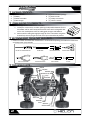
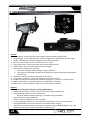
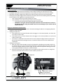
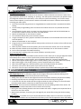
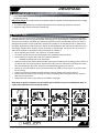
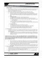
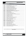
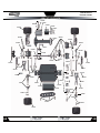
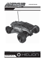
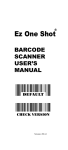
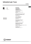
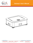
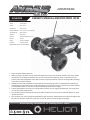
1/18th SCALE 4x4 ELECTRIC TRUGGY HLNA0038 LENGTH OWNER’S MANUAL AND EXPLODED VIEW 235mm (9.25in) WIDTH 172mm (6.8in) HEIGHT 81mm (3.2in) WHEELBASE 159mm (6.3in) WHEEL DIAMETER 42mm (1.65in) X 23mm (0.91in) TIRE DIAMETER 60mm (2.36in) WEIGHT* 540g (1.2lb) BATTERY 1,100mAh NiMH 6-CELL, 7.2v MOTOR 370 SIZE RADIO 2.4GHz 2-CHANNEL CHARGER AC WALL TRICKLE *APPROXIMATE OUT-OF-THE-BOX WEIGHT • EnƟre contents ©2011 Helion RC • Before using your product, review all documentaƟon and inspect the products carefully. If for some reason you decide it is not what you wanted, then do not conƟnue with unpacking, setup or operaƟon of your product. Your local HobbyTown USA® dealer cannot accept a product for return or exchange aŌer partaking in the afore menƟoned acƟons • Read and understand and follow all instrucƟons and accompanying material carefully before operaƟng or assembling your vehicle to prevent serious damage to your vehicle. Failure to complete these tasks properly or intenƟonal aversion to the content will be considered abuse and/or neglect • Product specicaƟons are subject to change without noƟce. Due to ongoing development, the actual product may vary from images shown • This product contains chemicals known to the State of California to cause cancer and birth defects or other reproducƟve harm • This product is not a toy! (14+) Recommended for ages 14 and up. Adult supervision required for ages under 18 years old. Contains small parts, keep out of reach of children 3 years of age and younger Exclusively Available at HobbyTown USA® # PACKAGE CONTENTS... 1. 2. 3. 4. [1] ANIMUS 18TR [1] BaƩery [1] Radio transmiƩer [1] Wall charger 5. 6. 7. 8. [1] DocumentaƟon package [1] Antenna tube [1] 4-Way cross wrench [1] 1.5mm L-wrench # ITEMS NEEDED TO COMPLETE... 1. [8] 1.5V AA type alkaline baƩeries for transmiƩer a. To help the environment, consider replacing the disposable baƩeries for this transmiƩer and for other household electronic items with rechargeable batteries. Visit a HobbyTown USA® for hobby grade chargers and baƩeries b. PaƟence while reading thoroughly through all of the instrucƟons and guides that will help ensure you get the most out of your new Helion RC product # RECOMMENDED TOOLS (NOT INCLUDED)... • Please use cauƟon and follow the manufacturer’s recommended operaƟng instrucƟons for these items and always wear eye protecƟon METRIC HEX SCREWDRIVER SET HOBBY KNIFE MINI SCREWDRIVERS CURVED HOBBY SCISSORS SIDE CUTTING PLIERS NEEDLE NOSE PLIERS BODY REAMER CA GLUE # THE ANIMUS 18TR... ANTENNA MOUNT SERVO ON/OFF MOTOR MOTOR PLUG ESC/ RECEIVER ANTENNA BATTERY PLUG 2 BATTERY GEAR COVER 1/18th SCALE 4x4 ELECTRIC TRUGGY # GETTING STARTED... 1. 2. 3. 4. 5. 6. 7. 8. 9. Carefully remove the box contents using side cuƫng pliers to cut the Ɵe straps Remove body and baƩery baƩery from vehicle to prepare for charging a. Read charging instrucƟons and understand all warnings and cauƟons before proceeding. This product is not a toy and should not be charged, operated, or maintained without supervision of an adult b. Return to this guide in the presence of the charging baƩery, remembering never to leave the battery unaƩended while charging Install antenna tube by sliding antenna into tube and inserƟng tube into mount on receiver. Be careful not to pinch the antenna during installaƟon. Install set screw verƟcally next to the antenna with included L wrench to secure the antenna in place. NOTE: Do NOT fold end of antenna over end of tube, this will reduce the range of the radio system and can cause interference when operaƟng your vehicle Install the [8] AA type alkaline baƩeries into the transmiƩer Install the fully charged baƩery into the vehicle, be sure to install the pins into the lower of the two holes in the baƩery mounƟng posts Ensure the motor is plugged into the ESC Ensure the switch is in the OFF posiƟon and connect the baƩery to the ESC Read and understand transmiƩer cauƟons and seƫng instrucƟons before use a. Conrm seƫngs for steering and throƩle trim Install body with 4 supplied clips; turn your equipment ON (radio rst!) and enjoy! # CHARGING THE BATTERY... • • • • • • Never leave the baƩery unaƩended while charging Never operate the charger without adult supervision Never charge a warm baƩery, always allow the baƩery to cool to room temperature before charging Never drop the charger or baƩery Never aƩempt to charge a damaged baƩery Inspect the baƩery and charger before use. Never charge a baƩery or charger if the wire or connector has been damaged or if the baƩery has experienced a short • Incorrect use of the baƩery, connecƟons, or charging equipment can cause personal injury or property damage • Never allow baƩeries or charger to come in contact with moisture at any Ɵme • Stop charging immediately if the baƩery or charger becomes hot or changes form during use NOTE: Only use chargers designed for use with NiMH baƩeries for the RC industry, using the supplied connector. Use of other (non-RC specic) chargers or connectors can permanently damage the baƩery and/or connected equipment. Genuine NiMH replacement baƩeries are available at your local HobbyTown USA®. 1. 2. 3. 4. 5. Plug the charger into a properly grounded standard US wall plug Plug the baƩery into the charger and place the baƩery on/in a non-ammable surface/container and away from any ammable objects A fully discharged baƩery should charge in approximately 4-5 hours a. CauƟon: Periodically monitor the temperature of the baƩery while charging, if the temperature exceeds 115°F (45°C), disconnect the baƩery from the charger and allow it to cool before reconnecƟng Unplug the baƩery from the charger when the baƩery is slightly warm to the touch, indicaƟng the battery had been fully charged a. NOTE: Using a peak detecƟon charger is recommended and will provide you with a faster and better charging experience. We recommend the Primal MulƟ-Chemistry charger by Radient RC. b. Warning: Never charge the included baƩery at a charge current exceeding 1.5A Remove charger from wall plug 3 # UNDERSTANDING YOUR TRANSMITTER... 4 8 7 5 9 1 2 10 6 3 12 11 Features: 1. Steering wheel: controls leŌ/right moƟon (designed to be operated with right hand) 2. ThroƩle trigger: controls forward/reverse moƟon (designed to be operated with leŌ index nger) 3. Handle: For holding the transmiƩer (designed to be held with leŌ hand) 4. Antenna: Transmits signal to the receiver located in the vehicle 5. Control panel cover: Covers control panel housing radio seƫng controls 6. ON/OFF Switch: Turns the power ON/OFF for the transmiƩer 7. Indicator lights: MulƟfuncƟon Green LED a. Solid Green: Adequate baƩery voltage for proper operaƟon b. Flashing Green: Low baƩery voltage warning, baƩeries should be replaced/recharged before conƟnued use 8. Bind buƩon: Used for binding the transmiƩer to the receiver 9. Steering Trim: Controls the “hands-oī ” leŌ/right direcƟon of the vehicle 10. ThroƩle Trim: Adjusts the motor speed to STOP when trigger is in “hands-oī ” (neutral) posiƟon 11. BaƩery compartment: houses [8] AA baƩeries for powering the transmiƩer 12. BoƩom cover: Closes the baƩery compartment, containing the AA baƩeries BaƩeries: WARNING: Do not aƩempt to charge non-rechargeable baƩeries • Remove the lower door from the transmiƩer to access the baƩery compartment • Install [8] AA type baƩeries into the compartment › Pay close aƩenƟon to baƩery polarity (+/-) indicators during installaƟon • Never mix brands or old/new baƩeries • Always remove dead baƩeries from the transmiƩer • If using rechargeable baƩeries, be sure to follow the manufacturer’s care and use instrucƟons • Rechargeable baƩeries must be removed from transmiƩer before charging • Always be sure to be responsible and protect the environment when disposing baƩeries. Your local HobbyTown USA® dealer provides a FREE baƩery disposal service 4 1/18th SCALE 4x4 ELECTRIC TRUGGY # ...TRANSMITTER CONTINUED... Standard operaƟon: • Turning the transmiƩer wheel to the leŌ from center makes the wheels on the vehicle turn LEFT • Turning the transmiƩer wheel to the right from center makes the wheels on the vehicle turn RIGHT • Pulling the transmiƩer trigger back towards the handle will make the vehicle accelerate forward • Pushing the transmiƩer trigger forward away from the handle will have the following aīects depending on the locaƟon of the trigger prior to pushing it forward › From a stop at neutral: the vehicle will travel in reverse › From pulled back: the vehicle will apply brakes to slow the speed » A second push forward of the trigger will apply reverse throƩle » WARNING: Causing the vehicle to make quick transiƟons from forward/reverse moƟon to the opposite direcƟon using the throƩle control can cause damage to your vehicle and will void the warranty Using your transmiƩer for the rst Ɵme: 1. Turn the transmiƩer ON and ensure the LED is lit SOLID indicaƟng the baƩeries are supplying adequate voltage for proper operaƟon 2. Seƫng the throƩle trim a. If the wheels spin in a forward direcƟon when the trigger is in the neutral posiƟon, turn down the trim unƟl the motor stops b. If the wheels spin in a reverse direcƟon when the trigger is in the neutral posiƟon, turn up the trim unƟl the motor stops c. There will be a “dead band” area where the trim can be adjusted a slight amount in either direcƟon and the wheels will not begin to move. It is ideal to have the trim set in the middle of this “dead band” 3. Seƫng the steering trim a. With your vehicle and transmiƩer turned on (and properly responding to transmiƩer inputs), set the vehicle down on the ground and slowly accelerate in a direcƟon directly away from you. If the vehicle veers slightly either to the leŌ or right, stop the vehicle and adjust the Steering Trim knob in the opposite direcƟon of the veer in small increments b. Reset the vehicle and re-test; adjust the trim as needed unƟl the vehicle travels in a straight line while the transmiƩer wheel remains at center locaƟon (“hands-oī ”) TURN LEFT [PULL] FORWARD THROTTLE TURN RIGHT [PUSH] REVERSE THROTTLE ON/OFF SWITCH LED INDICATOR BIND/ESC SET BUTTON 5 # ...TRANSMITTER CONTINUED... Binding the radio system: The process of allowing communicaƟon to occur between a 2.4GHz transmiƩer and receiver is called “binding” (someƟmes referred to as “matching” or “pairing”). The radio system included with your product comes pre-congured and bound from the factory. In the event your system loses binding, or one of the components has been replaced, you will need to re-bind the transmiƩer and receiver. Follow the below steps for re-binding your radio system 1. Ensure the transmiƩer has good (new or charged) baƩeries installed and that it is powered OFF before starƟng 2. Connect a fully charged baƩery pack to the electronics module and ensure it is powered OFF before starƟng 3. Use a toothpick (or other small, non-metal, non-sharp object) to depress and hold the bind buƩon on the electronics module and move the switch to the ON posiƟon 4. Release the bind buƩon on the electronics module 5. The red LED will ash quickly on the electronics module 6. Using the toothpick (or other), depress and hold the bind buƩon on the transmiƩer and move the switch to the ON posiƟon 7. Release the bind buƩon on the transmiƩer 8. The green LED on the transmiƩer will ash slowly and the red LED on the receiver will turn oī, then back on, ashing slowly 9. Move the power switches to the OFF posiƟon, rst on the electronics module, then on the transmiƩer 10. Move the power switches to the ON posiƟon, rst the transmiƩer, then on the electronics module 11. Ensure normal operaƟon of throƩle and steering 12. If you experience anything other than normal operaƟon, repeat the process Seƫng your ERS unit’s ESC: Properly seƫng the ESC to the transmiƩer ensures the ESC “knows” when you are trying to apply full throƩle or full brake/reverse. NOTE: It is best to perform this procedure with all baƩeries fully charged 1. With throƩle trigger in neutral posiƟon, press the Bind/Set buƩon for 3 seconds unƟl LED ashes 2. Without touching the throƩle trigger, leave in neutral posiƟon, press the Bind/Set buƩon once quickly 3. With throƩle trigger in full throƩle posiiton, press the Bind/Set buƩon once quickly 4. With the throƩle trigger set in full brake posiƟon, press the bind/set buƩon once quickly 5. Your ESC is now set, turn oī the power to your vehicle and turn it back on 6. Your ESC is now set to your transmiƩer. Always re-perform this procedure aŌer binding your radio # ADJUSTMENTS AND TUNING... The Animus 18TR has been engineered with some available tuning opƟons listed here for reference. Ride height adjustment: It is possible to adjust the ride height of your Animus 18TR by installing and or removing adjustment clips located directly above the shock springs • Adding more clips will raise the ride height of the vehicle and if done excessively may decrease stability. • Removing clips will lower the ride height and may cause the chassis to drag on the ground. • It is ideal to have the drive shaŌs level with the ground while the vehicle is siƫng on a at surface with the body installed. Add or remove clips to achieve the desired ride height Shock PosiƟon: There are two shock installaƟon locaƟons for the top mounƟng locaƟon of the shocks. The default posiƟon is inside (located closer to the centerline of the chassis) • Moving the shock mounƟng locaƟon to the outer locaƟon will result in a slightly more responsive feel on the front or rear of the vehicle • Always check and adjust, if necessary, the ride height of your vehicle aŌer moving the shock mounƟng locaƟons BaƩery posiƟon: It is possible to run your Animus 18TR with the baƩery either in a forward or rear posiƟon. • The baƩery is located in the rear posiƟon from the factory. This is ideal for opƟmum tracƟon and stability. 6 1/18th SCALE 4x4 ELECTRIC TRUGGY # ADJUSTMENTS AND TUNING CONTINUED... • If you desire more responsive steering and less stability, moving the baƩery to the forward posiƟon will provide this feeling Body Mount Height: The body mounts on the Animus 18TR are capable of verƟcal adjustment with 4 height opƟons available • The default seƫng allows for the lowest body posiƟon while maintaining component clearance • Adjust the body mounts to achieve a desired look # SAFETY TIPS... Although great for rst Ɵme users, Helion RC products are indeed advanced radio controlled vehicles with sensiƟve electronics and moving parts capable of causing injury if used improperly. Always use cauƟon and common sense as failure to operate your Helion RC product in a safe and responsible manner can result in damage to the product or other properƟes. Therefore this product is not intended for use or maintenance by children without direct adult supervision. Helion RC and HobbyTown USA® shall not be liable for any loss or damages, whether direct, indirect, special, incidental, or consequenƟal, arising from the use, misuse, or abuse of this product or any product required to operate or maintain it • Do not operate your vehicle in rain, electrical, or thunder storms • The vehicle should never be turned ON without the transmiƩer being turned ON • Never operate your vehicle when with low transmiƩer baƩeries › Indicated by ashing LED on the transmiƩer • Always check for proper radio system operaƟon (steering and throƩle) prior to leƫng go of the vehicle. If the vehicle does not respond properly to transmiƩer input, turn the vehicle OFF and inspect all connecƟons and operaƟng environment. Also see the TroubleshooƟng guide in this manual • Operate in a dry (no puddles), open environment away from traĸc, and cars (never run into the street for any reason) • Always turn oī both transmiƩer and ESC and disconnect the baƩery from the ESC aŌer use • Exercise extreme cauƟon when touching the motor immediately aŌer running your vehicle, it may be HOT and may cause a burn • Always allow the motor in your vehicle to cool before using again NOTE: Only use genuine replacement or aŌermarket parts available from your local HobbyTown USA® to ensure proper operaƟon of your Helion RC product. 7 # CARE AND MAINTENANCE... General Care: • Always use clean, dry cloth or soŌ bristle brush to clean your equipment • Never use chemical cleansers to avoid damage to the sensiƟve electronics and plasƟcs Maintenance: We want you to enjoy your product to its fullest potenƟal. For this to happen it is important to keep your product clean and properly maintained. Lack of cleaning and maintenance can cause component failure. For best and conƟnued performance from your product it is recommended to briey inspect your product for damage every few runs. Typically, a good Ɵme to do this is when changing the baƩery or while it is charging. If a problem is discovered, stop use immediately and seek repairs. ConƟnued use of failed components can cause more unnecessary damage to your product. Always remember to use genuine replacement parts from your local HobbyTown USA® dealer. Below is a list of items for inspecƟon. InspecƟon should not be limited to this list; if you noƟce any problem, listed or not, it is recommended to give it proper aƩenƟon 1. Electronics: The electronics included in your vehicle are not waterproof. It is criƟcal that they be kept away from moisture and that any moisture noƟced on or around them be immediately cleaned up a. Antenna: To achieve full operaƟng range with your radio system, it is criƟcal that the receiver antenna be installed properly and undamaged i. Inspect any exposed antenna for cuts or abrasions ii. Ensure there are no kinks in the antenna or antenna tube iii. Never fold the end of the antenna over the tube, this will reduce the range and damage the antenna 2. Gears: Periodically remove the gear cover to inspect the gears and ensure there is no debris in the gear compartment a. Proper gear mesh seƫng is crucial for proper operaƟon and life of gears in your product. It is important to have the pinion gear (aƩached to motor) as close to the spur gear (aƩached to drive shaŌ) as possible yet while providing a minimal amount of backlash. Backlash is the rotaƟon one gear has to make before contacƟng the other. Having the gear mesh set too Ɵght will cause excess load on the electrical components and may cause premature failure. Having gear mesh set too loose will cause excess wear and possible skipping of teeth during operaƟon thus causing excess wear and premature failure b. Checking the gear mesh i. Remove the spur gear cover ii. Press downward on the top deck close to the spur gear to hold in place iii. Check how much movement is allowed of the spur gear before the pinion gear moves (this is purely by feel, not visual) iv. If the spur gear is allowed to move more than a very small amount, or if it there is no backlash, the gear mesh must be adjusted v. Seƫng the gear mesh 01). Loosen the two screws on the boƩom of the chassis the hold the motor in place 02). Slide motor all the way to the spur gear, so there is no backlash 03). Move back slightly and hold the motor snugly in posiƟon while reƟghtening the bottom screws 04). Re-check the gear mesh and adjust again if necessary vi. Re-install the spur gear cover WARNING: Never operate your vehicle with the spur gear cover removed. Severe injury, damage to electrical components, and excessive wear and tear on drivetrain may result. 8 1/18th SCALE 4x4 ELECTRIC TRUGGY # ...MAINTENANCE CONTINUED... 3. 4. Shocks: Periodically inspect the shocks for smooth/free moƟon, leaking oil and dirt residue build up around the shaŌ a. Do not allow dirt to build up around the shock shaŌ and boƩom of the shock. Doing so will reduce the life of the shock and cause a shock to leak oil. Be sure to clean the shocks regularly with a clean and dry soŌ bristle brush and/or rag b. Signs to look out for determining if your shock needs to be maintained or rebuilt i. Oil around the shaŌ means the oil leaked from inside and needs to be replaced ii. Persistent oil around the shock shaŌ or lower porƟon of the shock typically points to damaged O-rings which will need replacing. See your local HobbyTown USA® for replacement parts iii. Relling your shocks: 01). Remove shock from vehicle, remove spring and top cap 02). With shock shaŌ extended, add oil to top of body (use only 100% silicone oil) 03). Slowly compress the shock shaŌ 50% of travel using a towel or paper napkin to clean up overowed oil 04). Slowly reinstall the shock cap and check for free moƟon of shock 05). It is normal for the shock to rebound (with the spring removed) aŌer full compression and release iv. Replacing the O-rings: 01). Disassemble shock and remove shaŌ from the body 02). Carefully remove lower cap by prying with a nger nail or similar object 03). Remove the O-rings and replace with genuine replacement parts 04). Re-assemble the shock following the Relling instrucƟons above Tires and wheels: a. Inspect the Ɵres to ensure they are properly glued to the wheels. The Ɵres on your vehicle come pre-glued from the factory; however aŌer running your vehicle it is possible for the glue to come loose in some areas. i. To reaƩach the Ɵre to the wheel, use hobby grade Cyanoacrylate (CA) glue and apply small amounts (one drop at a Ɵme) between the Ɵre and wheel. Allow the glue to fully dry before operaƟng your vehicle CauƟon: Be sure to use extreme care when using hobby-grade CA glue. It is specially formulated to cure quickly and create a strong bond. It will bond skin and can cause injury if used improperly. Follow manufacturer’s warnings and direcƟons when using CA glue. It is always recommended to wear eye protecƟon when maintaining your vehicle. ii. 5. When reinstalling Ɵres, use cauƟon when Ɵghtening the nuts that secure the wheels to the vehicle. Ensure they rotate freely but don’t wobble excessively. Over Ɵghtening the wheels will cause excess strain on the electrical and mechanical components of your vehicle. OperaƟng your vehicle under these condiƟons will void your warranty iii. Tire wear: Consequently running your vehicle will cause the Ɵres to eventually wear out. Be sure to obtain and use genuine replacement parts from your local HobbyTown USA® dealer General wear and tear: a. Use of your vehicle will cause general wear and tear which is not covered under warranty yet may necessitate replacement of components. ConƟnued operaƟon of your product with use of worn components may cause conƟnued damage to other components b. Be sure to regularly inspect your vehicle and accessories for excess wear and damaged components 9 # STORAGE AND DISPOSAL... Storage: • Always store all equipment in a cool dry place when not in use • Always disconnect the baƩeries before storage • Never store the baƩery, vehicle or transmiƩer in direct sunlight for extended periods of Ɵme • Never store the transmiƩer with baƩeries installed for extended periods of Ɵme. Doing so may allow the baƩeries to leak and cause permanent damage to the transmiƩer Disposal: Your product is equipped with NiMH baƩeries which are considered electronic waste and should never be discarded in standard garbage containers. Please visit your local HobbyTown USA® dealer and use the FREE baƩery disposal center for proper disposal/recycling # TROUBLESHOOTING GUIDE... Problem / Symptom Possible SoluƟon Charge baƩery Vehicle will not turn on Re/connect baƩery Replace baƩery Charge or change baƩeries TransmiƩer will not turn on Correct installaƟon Check receiver antenna for damage. Ensure Damaged or improperly installed antenna is properly installed in tube and Short radio range (Vereceiver antenna mount, extending perpendicular from the hicle stops responding ground to transmiƩer at short distances) TransmiƩer baƩery voltage too Replace baƩeries low Gear mesh too loose Tighten gear mesh for proper backlash Spur gears stripping Check for loose fasteners on spur gear cover Fasteners loose or missing and motor mount Trim not set properly Adjust steering trim Steering not responding Screws too Ɵght on steering as expected Adjust screws to allow for free moƟon components Trims not set properly Adjust throƩle and/or steering trim Vehicle not responding Radio system lost bind Re-bind radio system as expected to transmitCheck motor and baƩery plugs to ensure they ter Bad electrical connecƟons are fully connected BaƩery voltage too low Charge baƩery Drivetrain has too much fricƟon Check and slightly loosen wheel nuts Gear mesh too Ɵght Loosen gear mesh Vehicle top speed and acceleraƟon is slow Pinion gear is loose Check and Ɵghten set screw on motor pinion Check for missing wheel pins (behind wheel Drive pin missing or stripped hexes), or dogbone pins Shock O-ring seals are worn Replace O-rings and rell shock with oil Shocks and/or arms cov- Top shock cap too loose or over Check Ɵghtness (nger Ɵght), rell shock oil ered in oil Ɵghtened BoƩom shock cap dislodged Check installaƟon, rell shock oil 10 Possible Cause BaƩery voltage too low BaƩery not connected Damaged baƩery BaƩery voltage too low BaƩery/ies installed improperly 1/18th SCALE 4x4 ELECTRIC TRUGGY # SPARE PARTS LIST... HLNA0038........ANIMUS 18TR 4X4 ELECTRIC TRUGGY....................................................................................... HLNA0002........MAIN CHASSIS (ANIMUS) .......................................................................................................... HLNA0003........TOP PLATE, BATTERY STRAP, FOAM & POSTS (ANIMUS) ........................................................... HLNA0004........GEAR COVERS, GEAR BOXES (ANIMUS) .................................................................................... HLNA0005........FRONT & REAR SUSPENSION ARMS (ANIMUS) ......................................................................... HLNA0006........FRONT & REAR SHOCK TOWERS (ANIMUS) ............................................................................... HLNA0007........CASTER & STEERING BLOCKS, REAR HUBS (ANIMUS)............................................................... HLNA0008........STEERING BELL CRANKS & SERVO SAVER (ANIMUS) ................................................................ HLNA0009........DRIVE SHAFTS FRONT/REAR & CENTER (ANIMUS) ................................................................... HLNA0010........MOTOR MOUNT & INSERT (ANIMUS) ....................................................................................... HLNA0011........CAMBER, STEERING & SERVO LINKS WITH BALL STUDS (ANIMUS) .......................................... HLNA0012........FRONT & REAR SHOCK SET WITH BALL STUDS (ANIMUS) ......................................................... HLNA0013........SHOCK SEALS (ANIMUS) ............................................................................................................ HLNA0014........SHOCK SPRINGS (ANIMUS)........................................................................................................ HLNA0015........HINGE PINS AND WASHERS (ANIMUS) ...................................................................................... HLNA0016........DIFFERENTIAL OUTDRIVES & AXLES (ANIMUS) ........................................................................ HLNA0017........DRIVE PINS, WHEEL HEXES, BODY CLIPS, ANTENNA TUBES (ANIMUS) ..................................... HLNA0018........AXLE BEARING SET (ANIMUS) ................................................................................................... HLNA0019........GEARBOX BEARING SET (ANIMUS) ............................................................................................ HLNA0020........SPUR GEARS, 45T (ANIMUS)...................................................................................................... HLNA0021........PINION GEARS, 11T, 12T, 13T, 14T ............................................................................................. HLNA0022........COMPLETE DIFFERENTIAL & PINION GEAR (ANIMUS) .............................................................. HLNA0024........WHEELS & TIRES, LEFT & RIGHT (ANIMUS, SC) ......................................................................... HLNA0026........HARDWARE & SCREWS (ANIMUS)............................................................................................. HLNA0027........ESC, RECEIVER, SERVO (ERS) MODULE (ANIMUS) ..................................................................... HLNA0028........BATTERY, 7.2v 1,100mAh, NiMH ............................................................................................... HLNA0029........MOTOR, 370 4,200 RPM ........................................................................................................... HLNA0030........WALL CHARGER, TRICKLE, MICRO PLUG ................................................................................... HLNA0032........HELION 2.4GHZ 2-CHANNEL TRANSMITTER.............................................................................. HLNA0039........ANIMUS 18TR BODY, BLACK-BLUE ............................................................................................. HLNA0040........ANIMUS 18TR BODY, BLACK-RED .............................................................................................. HLNA0041........ANIMUS 18TR BODY, BLACK-YELLOW ........................................................................................ HLNA0042........ANIMUS 18TR BODY, CLEAR ...................................................................................................... HLNA0043........WHEELS & TIRES, LEFT & RIGHT (ANIMUS, TR) ......................................................................... HLNA0044........BUMPERS AND BODY MOUNTS (ANIMUS, TR).......................................................................... HLNA0045........ANIMUS 18TR OWNER’S MANUAL AND EXPLODED VIEW ........................................................ HLNA0050........REPLACMENT SERVO, ANIMUS (FS) .......................................................................................... See your local HobbyTown USA® for the latest in genuine replacement parts and accessories for your Helion RC product 11 1/18th SCALE 4x4 ELECTRIC TRUGGY ...ANIMUS 18TR EXPLODED VIEW... HLNA0050 HLNA0027 HLNA0008 HLNA0029 HLNA0043 HLNA0044 HLNA0010 HLNA0021 HLNA0003 HLNA0004 HLNA0044 HLNA0006 HLNA0006 HLNA0011 HLNA0009 HLNA0009 HLNA0008 HLNA0019 HLNA0019 HLNA0020 HLNA0044 HLNA0019 HLNA0044 HLNA0005 HLNA0012 HLNA0012 HLNA0011 HLNA0015 HLNA0011 HLNA0009 HLNA0022 HLNA0007 HLNA0015 HLNA0005 HLNA0015 HLNA0015 HLNA0002 HLNA0028 HLNA0019 HLNA0016 HLNA0017 HLNA0015 HLNA0007 HLNA0018 HLNA0003 HLNA0017 HLNA0043 12 13 # SHOCKS EXPLODED VIEW... HLNA0013 HLNA0012 HLNA0014 # DIFFERENTIAL EXPLODED VIEW... HLNA0022 HLNA0019 HLNA0019 HLNA0016 HLNA0022 14 HLNA0016 HLNA0026 1/18th SCALE 4x4 ELECTRIC TRUGGY # NOTES... 15 1/18th SCALE 4x4 ELECTRIC TRUGGY Exclusively Available at HobbyTown USA® HLNA0045 [REV A]