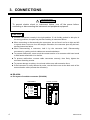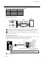
1
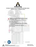
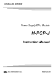
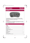
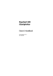
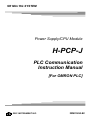
SR Mini HG SYSTEM Power Supply/CPU Module H-PCP-J PLC Communication Instruction Manual [For OMRON PLC] ® RKC INSTRUMENT INC. IMS01J04-E2 Modbus is a registered trademark of Schneider Electric. The name of each programmable controller (PLC) means the products of each manufacturer. Company names and product names used in this manual are the trademarks or registered trademarks of the respective companies. All Rights Reserved, Copyright 2004, RKC INSTRUMENT INC. Thank you for purchasing this RKC product. In order to achieve maximum performance and ensure proper operation of your new instrument, carefully read all the instructions in this manual. Please place the manual in a convenient location for easy reference. SYMBOLS WARNING : This mark indicates precautions that must be taken if there is danger of electric shock, fire, etc., which could result in loss of life or injury. CAUTION : This mark indicates that if these precautions and operating procedures are not taken, damage to the instrument may result. ! : This mark indicates that all precautions should be taken for safe usage. : This mark indicates important information on installation, handling and operating procedures. : This mark indicates supplemental information on installation, handling and operating procedures. : This mark indicates where additional information may be located. ! WARNING To prevent injury to persons, damage to instrument and equipment, a suitable external protection device shall be required. All wiring must be completed before power is turned on to prevent electric shock, fire or damage to instrument and equipment. This instrument must be used in accordance with the specifications to prevent fire or damage to instrument and equipment. This instrument is not intended for use in locations subject to flammable or explosive gases. Do not touch high-voltage connections such as power supply terminals, etc. to avoid electric shock. RKC is not responsible if this instrument is repaired, modified or disassembled by other than factory-approved personnel. Malfunction can occur and warranty is void under these conditions. IMS01J04-E2 i-1 CAUTION This product is intended for use with industrial machines, test and measuring equipment. (It is not designed for use with medical equipment and nuclear energy.) This is a Class A instrument. In a domestic environment, this instrument may cause radio interference, in which case the user may be required to take additional measures. This instrument is protected from electric shock by reinforced insulation. Provide reinforced insulation between the wire for the input signal and the wires for instrument power supply, source of power and loads. Be sure to provide an appropriate surge control circuit respectively for the following: - If input/output or signal lines within the building are longer than 30 meters. - If input/output or signal lines leave the building, regardless the length. This instrument is designed for installation in an enclosed instrumentation panel. All high-voltage connections such as power supply terminals must be enclosed in the instrumentation panel to avoid electric shock by operating personnel. All precautions described in this manual should be taken to avoid damage to the instrument or equipment. All wiring must be in accordance with local codes and regulations. All wiring must be completed before power is turned on to prevent electric shock, instrument failure, or incorrect action. The power must be turned off before repairing work for input break and output failure including replacement of sensor, contactor or SSR, and all wiring must be completed before power is turned on again. To prevent instrument damage as a result of failure, protect the power line and the input/output lines from high currents with a suitable overcurrent protection device with adequate breaking capacity such as fuse, circuit breaker, etc. Prevent metal fragments or lead wire scraps from falling inside instrument case to avoid electric shock, fire or malfunction. Tighten each terminal screw to the specified torque found in the manual to avoid electric shock, fire or malfunction. For proper operation of this instrument, provide adequate ventilation for heat dispensation. Do not connect wires to unused terminals as this will interfere with proper operation of the instrument. Turn off the power supply before cleaning the instrument. Do not use a volatile solvent such as paint thinner to clean the instrument. Deformation or discoloration will occur. Use a soft, dry cloth to remove stains from the instrument. To avoid damage to instrument display, do not rub with an abrasive material or push front panel with a hard object. Do not connect modular connectors to telephone line. When high alarm with hold action/re-hold action is used for Alarm function, alarm does not turn on while hold action is in operation. Take measures to prevent overheating which may occur if the control device fails. NOTICE This manual assumes that the reader has a fundamental knowledge of the principles of electricity, process control, computer technology and communications. The figures, diagrams and numeric values used in this manual are only for purpose of illustration. RKC is not responsible for any damage or injury that is caused as a result of using this instrument, instrument failure or indirect damage. RKC is not responsible for any damage and/or injury resulting from the use of instruments made by imitating this instrument. Periodic maintenance is required for safe and proper operation of this instrument. Some components have a limited service life, or characteristics that change over time. Every effort has been made to ensure accuracy of all information contained herein. RKC makes no warranty expressed or implied, with respect to the accuracy of the information. The information in this manual is subject to change without prior notice. No portion of this document may be reprinted, modified, copied, transmitted, digitized, stored, processed or retrieved through any mechanical, electronic, optical or other means without prior written approval from RKC. i-2 IMS01J04-E2 CONTENTS Page 1. OUTLINE ............................................................................... 1 2. COMMUNICATION SPECIFICATIONS ................................ 3 3. CONNECTIONS .................................................................... 4 4. SETTING ON THE H-PCP-J MODULE SIDE ....................... 6 4.1 PLC Data Memory Address Setting ................................................................. 6 4.2 Protocol Selection and Communication Setting ............................................... 8 4.3 PLC Scanning Time Setting............................................................................. 9 5. SETTING ON THE PLC SIDE ............................................. 10 6. COMMUNICATION DATA .................................................. 11 6.1 Request Command and Data Transfer .......................................................... 11 6.2 Data Processing Precautions ........................................................................ 15 6.3 Communication Data List............................................................................... 17 7. DATA MAP.......................................................................... 24 7.1 Reference to Data Map ................................................................................. 24 7.2 Data Map List ................................................................................................ 25 8. CURRENT TRANSFORMER (CT) MONITOR .................... 31 8.1 Setting on The H-PCP-J Module Side ........................................................... 33 8.2 Setting on The PLC Side ............................................................................... 37 8.3 Communication Data List............................................................................... 38 IMS01J04-E2 i-3 MEMO i-4 IMS01J04-E2 1. OUTLINE This manual describes the communication function of the SR Mini HG SYSTEM and the OMRON programmable controller (hereafter called PLC). This manual is attached when the model code of H-PCP-J module is H-PCP-J--D -03E. For details of the H-PCP-J module, see the Power Supply/CPU Module H-PCP-J Instruction Manual (IMS01J02-E). This manual should be used in conjunction with Hardware Quick Manual (IMS01V01-E). The SR Mini HG SYSTEM can be connected to the OMRON SYSMAC series without using any program. The SR Mini HG SYSTEM occupies the fixed area in the PLC data memory for each unit address. The control unit for SR Mini HG SYSTEM consists of the H-PCP-J module and temperature control function modules. RS-422A PLC OMRON SYSMAC series SR Mini HG SYSTEM control unit or RS-232C Converter RS-422A SR Mini HG SYSTEM control unit RS-422A SR Mini HG SYSTEM control unit RS-422A SR Mini HG SYSTEM control unit (Up to 4 units) In addition, the SR Mini HG SYSTEM can be monitored only current transformer (CT) input. For the data, see the 8. CURRENT TRANSFORMER (CT) MONITOR (P. 31). IMS01J04-E2 1 1. OUTLINE Usable units (OMRON SYSMAC series) Name Type High-order link unit C200H-LK202-V1, C500-LK203, C120-LK202-V1 (SYSMAC C series), etc. CPU unit with a built in communication port CPU unit of SYSMAC CS1 series Serial communication board CS1W-SCB41 (SYSMAC CS1 series), etc. Usable modules (SR Mini HG SYSTEM) The following function module data can be used in PLC communication (see “Data map” on page 24). In addition, data on other modules connected (TI, AI, AO, etc.) can be used on one more communication port (RKC communication or Modbus). Function module Type Temperature control module H-TIO-A H-TIO-B H-TIO-C H-TIO-D H-TIO-E H-TIO-F H-TIO-G H-TIO-H H-TIO-J H-TIO-P H-TIO-R Position proportioning control module * H-TIO-K Speed control module * H-SIO-A Cascade control module * H-CIO-A Current transformer input module H-CT-A (Up to 20 points/control unit are available) * There is restriction on usable data. Only data described in 6.3 Communication Data List (P. 17) can be used. For the function modules, see the Hardware Quick Manual (IMS01V01-E) or Hardware Instruction Manual (IMSRM15-E). 2 IMS01J04-E2 2. COMMUNICATION SPECIFICATIONS Interface: Based on RS-422A, EIA standard Connection method: RS-422A: 4-wire system, multi-drop connection Synchronous method: Start/stop synchronous type Communication speed: 9600 bps, 19200 bps, 38400 bps Communication speed can be selected with switch Data bit configuration: Start bit: Data bit: Parity bit: Stop bit: Protocol: OMRON SYSMAC C mode command protocol Unit number (Model number) 00 Usable command: C mode command RD: Word device read for each word WD: Word device write for each word CPU operation mode: Program mode or monitor mode Change it to monitor mode automatically when started with RUN mode. Maximum connections: 4 control units per communication port of PLC For the current transformer (CT) monitor function, 16 control units per communication port of PLC IMS01J04-E2 1 7 Even 2 3 3. CONNECTIONS ! WARNING To prevent electric shock or instrument failure, turn off the power before connecting or disconnecting the instrument and peripheral equipment. CAUTION Connect connectors correctly in the right position. If it is forcibly pushed in with pins in the wrong positions, the pins may be bent resulting in instrument failure. When connecting or disconnecting the connectors, do not force it too far to right and left or up and down, but move it on the straight. Otherwise, the connector pins may be bent, causing instrument failure. When disconnecting a connector, hold it by the connector itself. Disconnecting connectors by yanking on their cables can cause breakdowns. To prevent malfunction, never touch the contact section of a connector with bare hands or with hands soiled with oil or the like. To prevent malfunction, connect cable connectors securely, then firmly tighten the connector fastening screws. To prevent damage to cables, do not bend cables over with excessive force. If the instrument is easily affected by noise, use the ferrite core at the both ends of the communication cable (nearest the connector). RS-422A Pin layout of modular connector (RS-422A) COM.PORT1 1 2 3 4 5 6 4 H-PCP-J module R (A) R (B) SG T (B) T (A) SG IMS01J04-E2 3. CONNECTIONS Connector pin number and signal details (RS-422A) Pin No. 1 2 3 4 5 6 Signal name Receive data Receive data Signal ground Send data Send data Signal ground Symbol R (A) R (B) SG T (B) T (A) SG Diagram of RS-422A wiring Pair wire H-PCP-J () (+) () PLC OMRON SYSMAC series T (A) 5 SDA T (B) 4 SDB SG 3 SG R (A) 1 RDA R (B) 2 RDB SG 6 (+) Shielded twisted pair wire The 6-pin type modular connector should be used for the connection to the H-PCP-J module. Recommended model: TM4P-66P (Manufactured by HIROSE ELECTRIC CO., LTD.,) Because there is not SG, in case of SYSMAC CS1 series, electric wiring is unnecessary. Customer is requested to prepare a communication cable fit for the control unit to be connected by the PLC. Connection using our cable Connection cable W-BF-01 * (RKC product) can be used to connect the PLC. If noise is a factor, customer should use a twisted pair cable (not included) or something to that effect. * Shields of the cable are connected to SG (No. 6 pin) of the H-PCP-J connector. H-PCP-J Label symbol Red W-BF-01 RS-422A SG Blue T (A) Black SG SDA White R (A) SDB RDA Orange R (B) RDB T (B) Connect to the COM. PORT1 PLC OMRON SYSMAC series Cable type: W-BF-01-3000 (RKC product, Sold separately) [Standard cable length: 3 m] When wiring is to be made with W-BF-01 cable, connect as instructed in the above picture. (Just use the label symbol for leadwire identification and ignore the contents.) The details of the connectable connector for the PLC please also read the instruction manual for the used PLC. IMS01J04-E2 5 4. SETTING ON THE H-PCP-J MODULE SIDE 4.1 PLC Data Memory Address Setting Set the data memory address of each control unit using the unit address setting switch at the front of the H-PCP-J module. For this setting, use a small blade screwdriver. Unit address setting switch 456 CD AB E 23 F01 7 89 Setting range: 0 to 15 (0 to F: hexadecimal) H-PCP-J module Up to 4 SR Mini HG SYSTEMs can be connected to a PLC communication port. Therefore the data memory address uses the 4 SR Mini HG SYSTEMs as a group. The SR Mini HG SYSTEMs connected to the same PLC communication port sets the address in the same group. Set unit address of each group including 0, 4, 8 and C by all means. 0, 4, 8 and C work as a master of communication transfer. Set unit address within address range of PLC (CPU unit) to use. Group Group 1 Group 2 Group 3 Group 4 6 Unit address setting switch PLC data memory address 0 1 2 3 4 5 6 7 8 9 A B C D E F D1000 to D1499 D1500 to D1999 D2000 to D2499 D2500 to D2999 D3000 to D3499 D3500 to D3999 D4000 to D4499 D4500 to D4999 D5000 to D5499 D5500 to D5999 D6000 to D6499 D6500 to D6999 D7000 to D7499 D7500 to D7999 D8000 to D8499 D8500 to D8999 IMS01J04-E2 4. SETTING ON THE H-PCP-J MODULE SIDE Setting example: PLC When group 2 is used Unit address 4 SR Mini HG SYSTEM control unit Data memory address: D3000 to D3499 Unit address 5 SR Mini HG SYSTEM control unit Data memory address: D3500 to D3999 Address in the same group is set Unit address 6 SR Mini HG SYSTEM control unit Data memory address: D4000 to D4499 Unit address 7 SR Mini HG SYSTEM control unit IMS01J04-E2 Data memory address: D4500 to D4999 7 4. SETTING ON THE H-PCP-J MODULE SIDE 4.2 Protocol Selection and Communication Setting Match the setting of data bit configuration, communication speed and communication protocol with the PLC communication specification by COM.PORT1/COM.PORT2 setting switch (SW2). Setting example to recommend is shown in the following. COM.PORT1/COM.PORT2 setting switch (SW2) H-PCP-J module ON 1 2 3 4 5 6 7 8 Data bit configuration Communication speed (Set the same as PLC.) Communication protocol Factory set value: All OFF Right side view Data bit configuration SW2 Data bit configuration 1 2 ON ON Data 7-bit, Even parity, Stop 2-bit Communication speed SW2 Set the same as PLC. Communication speed 3 4 OFF OFF 9600 bps ON OFF 19200 bps OFF ON 38400 bps ON ON Don't set this one Protocol SW2 8 5 6 7 8 ON OFF ON OFF Protocol OMRON SYSMAC series special protocol IMS01J04-E2 4. SETTING ON THE H-PCP-J MODULE SIDE 4.3 PLC Scanning Time Setting Set the PLC scanning time (time of waiting for a response from the PLC) so as to adapt to the environment used. The PLC scanning time is set via host communication (RKC communication or Modbus). PLC scanning time setting Setting range: 0 to 3000 ms (Factory set value: 10 ms) [Setting example] Set PLC scanning time to any value more than twice as long as the maximum scanning time of PLC. If PLC scanning time is extremely short (When at a factory set value of 10 ms as an example), the SR Mini HG SYSTEM may detect the time-out not conducting normal communication processing. The maximum scanning time of PLC differs depending on the CPU processing speed, I/O unit configuration and the user program capacity of the PLC. For the PLC scanning time setting (Identifier ST), see the Power Supply/CPU Module H-PCP-J Instruction Manual (IMS01J02-E). IMS01J04-E2 9 5. SETTING ON THE PLC SIDE Set the PLC as follows. (Recommend setting example) Item Description Serial communication mode High-order link Unit number (Model number) 0 Start bit 1 Data bit 7 Stop bit 2 Parity bit Even Transmission speed Set the same as SR Mini HG SYSTEM I/O port selection RS-422A Synchronization selection Internal synchronization CTS selection 0 V (always ON) 5 V supply OFF Termination resistor Termination resistor is inserted The setting item varies depending on the PLC. The details of the setting procedure for the PLC please also read the instruction manual for the used PLC. 10 IMS01J04-E2 6. COMMUNICATION DATA 6.1 Request Command and Data Transfer Data transfer between PLC and SR Mini HG SYSTEM are executed by request command. Request command “0: Monitor (PLC SR Mini HG SYSTEM)” Command which status requests the SR Mini HG SYSTEM to write data such as temperature measured values, etc. (attribute: RO) to the PLC side. The SR Mini HG SYSTEM always repeats data writing until “1: Setting” or “2: Set value monitor” is set to the request command. The PCP communication is set to “1: Writing on monitor data” during data transfer. Request command “1: Setting (PLC SR Mini HG SYSTEM)” Command which requests the SR Mini HG SYSTEM to read data such as temperature set values, etc. (attribute: R/W or WO) from the PLC side. Just when “1: Setting” is set to the request command, the SR Mini HG SYSTEM starts reading the data from the PLC side. The PCP communication status is set to “2: Reading out setting data” during data transfer. After the data is transferred, the request command and PCP communication status returns to “0: Monitor” and “1: Writing on monitor data,” respectively. Request command “2: Set value monitor (PLC SR Mini HG SYSTEM)” Command which requests the SR Mini HG SYSTEM to write data such as temperature set values, etc. (attribute: R/W) to the PLC side. Just when “2: Set value monitor” is set to the request command, the SR Mini HG SYSTEM starts writing the data to the PLC side. The PCP communication status is set to “3: Writing on setting data” during data transfer. After the data is transferred, the request command and PCP communication status returns to “0: Monitor” and “1: Writing on monitor data,” respectively. IMS01J04-E2 11 6. COMMUNICATION DATA Data transfer procedures Change each set value of SR Mini HG SYSTEM from the PLC after the initial settings are made. If each set value of SR Mini HG SYSTEM is changed from the PLC without setting the initial values, it is re-written to 0 with each set value of the PLC at that time set to 0. Initial Setting (When transmit data of temperature setting values from SR Mini HG SYSTEM to PLC) Start Turn on power of each instrument Set “2” to the request command NO PCP communication state = 3 ? When 2 (Set value monitor) is set to request command, the SR Mini HG SYSTEM starts writing the data items such as temperature set value, etc. (attribute: R/W) to the PLC side. If 3 (Writing on setting data) is set to PCP communication state in the PLC, this indicates that SR Mini HG SYSTEM data items such as temperature set value, etc. (attribute: R/W) are being written into the PLC. YES Wait time NO PCP communication state = 1 ? YES Reserve data write time as wait time. In addition, process data in each item as indefinite during this period. Waiting time (for 38400 bps): Approx. 1 second/control unit If 1 (Writing on monitor data) is set to PCP communication state in the PLC, this indicates that SRV data items such as temperature set value, etc. (attribute: R/W) have been written to start writing SR Mini HG SYSTEM data items such as temperature measured values (PV), etc. (attribute: RO) into the PLC. End 12 IMS01J04-E2 6. COMMUNICATION DATA Data setting (When transmit data of temperature setting values from PLC to SR Mini HG SYSTEM) Start Set temperature set value (SV) and other setting data to each register (memory) in the PLC. Set “1” to the request command [Data setting] When 1 (Setting) is set to request command, the SR Mini HG SYSTEM starts reading the temperature set value data set to the register (memory) on the PLC side. NO PCP communication state = 2 ? If 2 (Reading out setting data) is set to PCP communication state in the PLC, this indicates that temperature set values data are being read from the PLC. YES Wait time NO PCP communication state = 1 ? YES Reserve data read time as wait time. In addition, process data in each item as indefinite during this period. Waiting time (for 38400 bps): Approx. 2 seconds/control unit If 1 (Writing on monitor data) is set to PCP communication state in the PLC, this indicates that temperature set value data have been read to start writing SR Mini HG SYSTEM data items such as temperature measured values (PV) etc. (attribute: RO) into the PLC. A Continued on the next page. IMS01J04-E2 13 6. COMMUNICATION DATA Continued from the previous page. A Set “2” to the request command NO PCP communication state = 3 ? [Confirmation of setting data] When 2 (Set value monitor) is set to request command, the SR Mini HG SYSTEM starts writing the temperature set value data set to the PLC side. If 3 (Writing on setting data) is set to PCP communication state in the PLC, this indicates that SR Mini HG SYSTEM temperature set value data are being written into the PLC. YES Wait time NO PCP communication state = 1 ? YES Reserve data write time as wait time. In addition, process data in each item as indefinite during this period. Waiting time (for 38400 bps): Approx. 1 second/control unit If 1 (Writing on monitor data) is set to PCP communication state in the PLC, this indicates that temperature set values have been written to start writing SR Mini HG SYSTEM data items such as temperature measured values (PV), etc. (attribute: RO) into the PLC. End 14 IMS01J04-E2 6. COMMUNICATION DATA 6.2 Data Processing Precautions With PLC communication, the maximum number of channels per unit address is 20. Read data of unused channel and undefined address is 0. The data type is treated as binary data with a sign and without a decimal point. For this reason, carefully express and set the data. (excluding the TIO status) [Example] Heat-side proportional band Initial value of internal data: 3.0 Communication data: 30 If the data range error occurs during data setting, “Setting error” (bit 8 in the TIO status) is set to ON in the channel where the error occurs. The SR Mini HG SYSTEM continues operation at the present set value without updating the data. Any attempt to write to an unused channel is not processed as an error. The autotuning (AT) function starts its execution with PID/AT transfer and the request command set to “1: AT operation” and “1: Setting,” respectively. After the autotuning function finishes its execution, PID/AT transfer returns to “0: PID control operation” and thus the PID constants are updated. When the PLC communication status is selected by selecting the H-PCP-J module DO type (Identifier VU), the digital output (DO) is turned on or off according to the status of communication between the H-PCP-J module and PLC. Communication error PLC communication status (H-PCP-J module DO) Operation mode When the communication is error after the power ON immediately OFF “1: Monitor” When the communication is error during operation OFF Same as mode before the communication error If communication between the H-PCP-J module and PLC is ready, the PLC communication status (H-PCP-J module DO) is turned on to enable operation to continue. The H-PCP-J module DO type selection (Identifier VU) is set by host communication. For the host communication, see the Power Supply/CPU Module H-PCP-J Instruction Manual (IMS01J02-E). IMS01J04-E2 15 6. COMMUNICATION DATA Some communication data may become invalid depending on the module selection or the configuration of the SR Mini HG System control unit. If any one of the conditions listed below occurs and data items written are within the setting range, read data becomes 0. Under these conditions, no error response message will occur. When heat/cool control, manual output value and auto/manual transfer are invalid. When heat control, cool-side manipulated output, cool-side proportional band and overlap/deadband are invalid. When ON/OFF control, cool-side manipulated output, heat-side and cool-side proportional band, integral time, derivative time and overlap/deadband are invalid. When the H-CT-A module is not provided, current transformer input measured value and heater break alarm set value are invalid. 16 IMS01J04-E2 6. COMMUNICATION DATA 6.3 Communication Data List Name : Item stored in the memory area. [ ]: The functional module name that data becomes valid is written. Attributes RO: At the time of request command “0: Monitor,” SR Mini HG SYSTEM writes in data. (SR Mini HG SYSTEM PLC) R/W: At the time of request command “1: Setting,” SR Mini HG SYSTEM read out data. At the time of request command “2: Set value monitor,” SR Mini HG SYSTEM writes in data. (SR Mini HG SYSTEM PLC) WO: At the time of request command “1: Setting,” SR Mini HG SYSTEM read out data. (SR Mini HG SYSTEM PLC) Structure C: Data for each channel U: Data for each unit address Name Temperature set value (SV) [H-TIO-, H-CIO-A] Attri- Strucbute ture R/W C Motor speed set value [H-SIO-A] Factory set value Data range TC/RTD input: Within input range (Within setting limiter) Current/voltage input: Within display scale range (Within setting limiter) Within display scale range (Within setting limiter) Alarm 1 set value [H-TIO-, H-CIO-A, H-SIO-A] R/W C Alarm 2 set value [H-TIO-, H-CIO-A, H-SIO-A] R/W C TC/RTD input: Within input range or span range Current/voltage input, H-SIO-A: Within display scale range or span range 0 The position of the decimal point differs depending on the input range. See Factory set value table of Alarm 1/ Alarm 2 set value * * Factory set value table of Alarm 1/Alarm 2 set value Input type TC/RTD input Current/voltage input H-SIO-A 1 Alarm type Process high alarm Process low alarm Deviation high alarm, Deviation high/low alarm, Band alarm Deviation low alarm No alarm function Process high alarm Process low alarm Deviation high alarm, Deviation high/low alarm, Band alarm Deviation low alarm No alarm function Alarm 1 set value Input range (high limit) Input range (low limit) 50 C 1 Alarm 2 set value Input range (high limit) Input range (low limit) 50 C 1 50 C 1 Input range (high limit) 100 (100.0) % 0 (0.0) % 50 (50.0) % 50 C 1 Input range (low limit) 100 (100.0) % 0 (0.0) % 50 (50.0) % 50 (50.0) % 100 (100.0) % 50 (50.0) % 100 (100.0) % The position of the decimal point differs depending on the input range. Continued on the next page. IMS01J04-E2 17 6. COMMUNICATION DATA Continued from the previous page. Attribute Structure Heater break alarm set value [H-CT-A] R/W C 0.0 to 100.0 A or 0.0 to 30.0 A For the current transformer (CT) input of the H-CT-A module. Allocates the channels for H-TIO- module to the input channels of H-CT-A module by CT channel setting. For the CT channel setting, see the Power Supply/CPU Module H-PCP-J Instruction Manual (IMS01J02-E). 0.0 Operation mode transfer [H-TIO-, H-CIO-A, H-SIO-A] R/W C 0: Unused If set to “Unused,” no control, monitor or alarm monitor is performed. 1: Monitor If set to “Monitor,” only the monitor is performed. No control or alarm monitor is performed. 2: Alarm If set to “Alarm,” monitor or alarm monitor is performed. No control is performed. 3: Normal Selected to normal mode to perform control, monitor or alarm monitor. 3 Auto/Manual transfer [H-TIO-, H-CIO-A] R/W C 0: Auto 1: Manual Setting will be invalid in ON/OFF control and heat/cool control. 0 Manual output value [H-TIO-, H-CIO-A] R/W C 5.0 to 105.0 % Setting will be invalid in ON/OFF control and heat/cool control. 0.0 Overlap/deadband [H-TIO-, H-CIO-A] R/W C 10.0 to 10.0 % of span 0.0 Heat-side proportional band [H-TIO-, H-CIO-A, H-SIO-A] R/W C 0.1 to 1000.0 % of span H-TIO-, H-CIO-A: 3.0 H-SIO-A: 300.0 Cool-side proportional band [H-TIO-, H-CIO-A] R/W C 0.1 to 1000.0 % of span 3.0 Name Factory set value Data range Continued on the next page. 18 IMS01J04-E2 6. COMMUNICATION DATA Continued from the previous page. Attribute Structure Integral time [H-TIO-, H-CIO-A, H-SIO-A] R/W C 1 to 3600 seconds H-TIO-, H-CIO-A: 240 H-SIO-A: 2 Derivative time [H-TIO-, H-CIO-A, H-SIO-A] R/W C 0 to 3600 seconds (0: PI action) H-TIO-, H-CIO-A: 60 H-SIO-A: 0 PID/AT transfer * [H-TIO-, H-CIO-A, H-SIO-A] R/W C 0: PID control operation 1: AT (Autotuning) operation Name Factory set value Data range 0 The autotuning (AT) function starts its execution with PID/AT transfer and the request command set to “1: AT operation” and “1: Setting,” respectively. After the autotuning function finishes its execution, PID/AT transfer returns to “0: PID control operation.” * Autotuning (AT) is the function which automatically measures, calculates and sets the optimum PID constants according to the set temperature. Caution for using the Autotuning (AT) When a temperature change (UP and/or Down) is 1C or less per minute during Autotuning, Autotuning may be cancelled before calculating PID values. In that case, adjust the PID values manually. It is possible to happen when the set value is around the ambient temperature or is close to the maximum temperature achieved by the load. The following is the conditions necessary to carry out autotuning and the conditions which will cause the autotuning to stop. Conditions necessary for autotuning: The autotuning should be executed after satisfying all of the following conditions: Operation mode conditions: Auto/Manual transfer Auto mode PID/AT transfer PID control mode Control RUN/STOP transfer Control RUN mode The measured value (PV) is without input error range [Input error determination point (high) Measured value (PV) Input error determination point (low)]. The output limiter high limit should be more than 0.1 % and the output limiter low limit should be less than 99.9 %. When operation mode is set to “Normal (Can be controlled ).” When the autotuning is finished, the display of each channel automatically returns to “0: PID control operation.” Continued on the next page. IMS01J04-E2 19 6. COMMUNICATION DATA Continued from the previous page. Conditions which will cause the autotuning to stop: When the temperature set value (SV) is changed. When the memory area is changed. When the PV bias value is changed. When the AT bias value is changed. When transfer to Manual mode using the Auto/Manual transfer. When the measured value (PV) goes to input error range [Measured value (PV) Input error determination point (high) or Input error determination point (low) Measured value (PV)]. When the power is cut off. When FAIL occurs in the module whose channel is under the autotuning. Otherwise, when FAIL occurs in the H-PCP-J module. When transfer to the PID control mode by the PID/AT transfer. When operation mode is set to “Unused,” “Monitor” or “Alarm.” When the Control RUN/STOP function is changed to the “Control STOP” function. When the above-mentioned conditions to stop the autotuning occurs, the autotuning is immediately stopped and switch over to the PID control mode. The PID constants return to the values at the start of the autotuning. Continued on the next page. 20 IMS01J04-E2 6. COMMUNICATION DATA Continued from the previous page. Name Temperature measured value (PV) [H-TIO-, H-CIO-A] Attribute Structure RO C Motor speed measured value [H-SIO-A] Data range Factory set value TC/RTD input: Within input range Current/voltage input: Within display scale range Within display scale range Heat-side manipulated output value [H-TIO-, H-CIO-A] RO C 0.5 to 105.0 % Cool-side manipulated output value [H-TIO-, H-CIO-A] RO C 0.5 to 105.0 % Current transformer input measured value [H-CT-A] RO C 0.0 to 100.0 A or 0.0 to 30.0 A Current transformer (CT) input measured value of the H-CT-A module. Allocates the channels for H-TIO- module to the input channels of H-CT-A module by CT channel setting. For the CT channel setting, see the Power Supply/CPU Module H-PCP-J Instruction Manual (IMS01J02-E). TIO status [H-TIO-, H-CIO-A, H-SIO-A] RO C Each operation status is assigned as a bit image in binary numbers. Bit data bit 0: Heat-side manipulated output status bit 1: Unused bit 2: Alarm 1 status bit 3: Alarm 2 status bit 4: Burnout status bit 5: Heater break alarm status bit 6: Control loop break alarm (LBA) status bit 7: Temperature rise completion status bit 8: Setting error bit 9 to 15: Unused Data 0: OFF 1: ON bit 15 ·························· bit 0 Bit image: 0000000000000000 [Decimal number: 0 to 509] Set value monitor [H-TIO-, H-CIO-A, H-SIO-A] RO C TC/RTD input: Within input range Current/voltage input, H-SIO-A: Within display scale range Continued on the next page. IMS01J04-E2 21 6. COMMUNICATION DATA Continued from the previous page. Attribute Structure Request command [H-PCP-J] R/W U 0: Monitor Command which requests the SR Mini HG SYSTEM to write data such as temperature measured values, etc. (attribute: RO) to the PLC side. The SR Mini HG SYSTEM always repeats data writing until “1: Setting” or “2: Set value monitor” is set to the request command. The PCP communication status is set to “1: Writing on monitor data” during data transfer. 1: Setting Command which requests the SR Mini HG SYSTEM to read data such as temperature set values, etc. (attribute: R/W or WO) from the PLC side. Just when “1: Setting” is set to the request command, the SR Mini HG SYSTEM starts reading the data from the PLC side. The PCP communication status is set to “2: Reading out setting data” during data transfer. After the data is transferred, the request command and PCP communication status returns to “0: Monitor” and “1: Writing on monitor data,” respectively. 2: Set value monitor Command which requests the SR Mini HG SYSTEM to write data such as temperature set values, etc. (attribute: R/W) to the PLC side. Just when “2: Set value monitor” is set to the request command, the SR Mini HG SYSTEM starts writing the data to the PLC side. The PCP communication status is set to “3: Writing on setting data” during data transfer. After the data is transferred, the request command and PCP communication status returns to “0: Monitor” and “1: Writing on monitor data,” respectively. 0 PCP communication status [H-PCP-J] RO U 1: Writing on monitor data During monitor data of attribute RO is written to PLC 2: Reading out setting data During setting data of attribute R/W or WO is read from PLC 3: Writing on setting data During setting data of attribute R/W is written to PLC Name Factory set value Data range Continued on the next page. 22 IMS01J04-E2 6. COMMUNICATION DATA Continued from the previous page. Name Attribute StrucData range ture U The numbers 0 and then 1 are repeated in every communication period. The SR Mini HG SYSTEM rewrites 0 and 1 in this area alternately like 0 1 0 in every communication period. It is possible to determine whether or not the SR Mini HG SYSTEM makes communication by monitoring this area periodically using the PLC program. Factory set value PCP normal communication flag [H-PCP-J] RO Memory area number [H-TIO-, H-CIO-A, H-SIO-A] WO U 1 to 8 Data reading is always made from the PLC regardless of the request command. Any numeric value other than 1 to 8 becomes invalid. Changing the memory area automatically writes each set value to the PLC. Control RUN/STOP transfer * [H-PCP-J] WO U 0: Control STOP 1: Control RUN PV bias [H-TIO-, H-CIO-A, H-SIO-A] R/W C 5.00 to 5.00 % of span ZK-1103 specification: Input span to Input span Setting change rate limiter [H-TIO-, H-CIO-A, H-SIO-A] R/W C 0.0 to 100.0 % of span/minute 0.00 ZK-1103: 0a 0.0 * When the control RUN/STOP holding setting is set to “Not hold” or “Hold”: The control RUN/STOP transfer setting is always read from the PLC regardless of the request command. Any numeric value other than 0 and 1 becomes invalid. When the control RUN/STOP holding setting is set to “Start-up from control RUN status”: As the control RUN/STOP transfer setting is always set to “1: Control RUN,” any value set to the control RUN/STOP transfer becomes invalid. The Control RUN/STOP holding (Identifier X1) is set by host communication. For the host communication, see the Power Supply/CPU Module H-PCP-J Instruction Manual (IMS01J02-E). a Unit (C, F, etc.) and decimal point position (No decimal place, One decimal place, Two decimal places or Three decimal places) depends on input range type. IMS01J04-E2 23 7. DATA MAP 7.1 Reference to Data Map This data map summarizes the data (data memory) addresses, channels and names that can be used with PLC. For details on each data range, see the 6.3 Communication Data List (P. 17). (b) (a) (c) Unit address 0 Unit address 1 Unit address 2 Unit address 3 D1000 to D1019 D1500 to D1519 D2000 to D2019 D2500 to D2519 Temperature set value (SV) D1020 to D1039 D1520 to D1539 D2020 to D2039 D2520 to D2539 Alarm 1 set value Name CH1 to CH20 CH1 to CH20 (a) Unit address: Unit address of SR Mini HG SYSTEM 24 (b) Name: Data names (c) Address: Data (data memory) addresses Data memory address is expressed in decimal number IMS01J04-E2 7. DATA MAP 7.2 Data Map List Unit address 0 to 3 (Group 1) Unit address 0 Unit address 1 Unit address 2 Unit address 3 D1000 to D1019 D1020 to D1039 D1040 to D1059 D1060 to D1079 D1080 to D1099 D1100 to D1119 D1120 to D1139 D1140 to D1159 D1160 to D1179 D1180 to D1199 D1200 to D1219 D1220 to D1239 D1240 to D1259 D1260 to D1279 D1280 to D1299 D1300 to D1319 D1320 to D1339 D1340 to D1359 D1360 to D1379 D1380 D1500 to D1519 D1520 to D1539 D1540 to D1559 D1560 to D1579 D1580 to D1599 D1600 to D1619 D1620 to D1639 D1640 to D1659 D1660 to D1679 D1680 to D1699 D1700 to D1719 D1720 to D1739 D1740 to D1759 D1760 to D1779 D1780 to D1799 D1800 to D1819 D1820 to D1839 D1840 to D1859 D1860 to D1879 D1880 D2000 to D2019 D2020 to D2039 D2040 to D2059 D2060 to D2079 D2080 to D2099 D2100 to D2119 D2120 to D2139 D2140 to D2159 D2160 to D2179 D2180 to D2199 D2200 to D2219 D2220 to D2239 D2240 to D2259 D2260 to D2279 D2280 to D2299 D2300 to D2319 D2320 to D2339 D2340 to D2359 D2360 to D2379 D2380 D2500 to D2519 D2520 to D2539 D2540 to D2559 D2560 to D2579 D2580 to D2599 D2600 to D2619 D2620 to D2639 D2640 to D2659 D2660 to D2679 D2680 to D2699 D2700 to D2719 D2720 to D2739 D2740 to D2759 D2760 to D2779 D2780 to D2799 D2800 to D2819 D2820 to D2839 D2840 to D2859 D2860 to D2879 D2880 Request command D1381 D1881 D2381 D2881 PCP communication status D1382 D1882 D2382 D2882 PCP normal communication flag Name Temperature set value (SV) CH1 to CH20 Alarm 1 set value CH1 to CH20 Alarm 2 set value CH1 to CH20 Heater break alarm set value (H-CT-A module) CH1 to CH20 Operation mode transfer CH1 to CH20 Auto/Manual transfer CH1 to CH20 Manual output value CH1 to CH20 Overlap/deadband CH1 to CH20 Heat-side proportional band CH1 to CH20 Cool-side proportional band CH1 to CH20 Integral time CH1 to CH20 Derivative time CH1 to CH20 PID/AT transfer CH1 to CH20 Temperature measured value (PV) CH1 to CH20 Heat-side manipulated output value CH1 to CH20 Cool-side manipulated output value CH1 to CH20 Current transformer input measured value (H-CT-A module) CH1 to CH20 TIO status CH1 to CH20 Set value monitor CH1 to CH20 Continued on the next page. IMS01J04-E2 25 7. DATA MAP Continued from the previous page. Unit address 0 Unit address 1 Unit address 2 Unit address 3 D1383 to D1389 D1390 D1883 to D1889 D1890 D2383 to D2389 D2390 D2883 to D2889 D2890 D1391 D1392 to D1399 D1400 to D1419 D1420 to D1439 D1440 to D1499 D1891 D1892 to D1899 D1900 to D1919 D1920 to D1939 D1940 to D1999 D2391 D2392 to D2399 D2400 to D2419 D2420 to D2439 D2440 to D2499 D2891 D2892 to D2899 D2900 to D2919 D2920 to D2939 D2940 to D2999 Name Do not use this address range Memory area number Control RUN/STOP transfer Do not use this address range PV bias CH1 to CH20 Setting change rate limiter CH1 to CH20 Do not use this address range Unit address 4 to 7 (Group 2) Unit address 4 Unit address 5 Unit address 6 Unit address 7 D3000 to D3019 D3020 to D3039 D3040 to D3059 D3060 to D3079 D3080 to D3099 D3100 to D3119 D3120 to D3139 D3140 to D3159 D3160 to D3179 D3180 to D3199 D3200 to D3219 D3220 to D3239 D3500 to D3519 D3520 to D3539 D3540 to D3559 D3560 to D3579 D3580 to D3599 D3600 to D3619 D3620 to D3639 D3640 to D3659 D3660 to D3679 D3680 to D3699 D3700 to D3719 D3720 to D3739 D4000 to D4019 D4020 to D4039 D4040 to D4059 D4060 to D4079 D4080 to D4099 D4100 to D4119 D4120 to D4139 D4140 to D4159 D4160 to D4179 D4180 to D4199 D4200 to D4219 D4220 to D4239 D4500 to D4519 D4520 to D4539 D4540 to D4559 D4560 to D4579 D4580 to D4599 D4600 to D4619 D4620 to D4639 D4640 to D4659 D4660 to D4679 D4680 to D4699 D4700 to D4719 D4720 to D4739 Name Temperature set value (SV) CH1 to CH20 Alarm 1 set value CH1 to CH20 Alarm 2 set value CH1 to CH20 Heater break alarm set value (H-CT-A module) CH1 to CH20 Operation mode transfer CH1 to CH20 Auto/Manual transfer CH1 to CH20 Manual output value CH1 to CH20 Overlap/deadband CH1 to CH20 Heat-side proportional band CH1 to CH20 Cool-side proportional band CH1 to CH20 Integral time CH1 to CH20 Derivative time CH1 to CH20 Continued on the next page. 26 IMS01J04-E2 7. DATA MAP Continued from the previous page. Unit address 4 Unit address 5 Unit address 6 Unit address 7 D3240 to D3259 D3260 to D3279 D3280 to D3299 D3300 to D3319 D3320 to D3339 D3340 to D3359 D3360 to D3379 D3380 D3740 to D3759 D3760 to D3779 D3780 to D3799 D3800 to D3819 D3820 to D3839 D3840 to D3859 D3860 to D3879 D3880 D4240 to D4259 D4260 to D4279 D4280 to D4299 D4300 to D4319 D4320 to D4339 D4340 to D4359 D4360 to D4379 D4380 D4740 to D4759 D4760 to D4779 D4780 to D4799 D4800 to D4819 D4820 to D4839 D4840 to D4859 D4860 to D4879 D4880 Request command D3381 D3881 D4381 D4881 PCP communication status D3382 D3383 to D3389 D3390 D3882 D3883 to D3889 D3890 D4382 D4383 to D4389 D4390 D4882 D4883 to D4889 D4890 PCP normal communication flag D3391 D3392 to D3399 D3400 to D3419 D3420 to D3439 D3440 to D3499 D3891 D3892 to D3899 D3900 to D3919 D3920 to D3939 D3940 to D3999 D4391 D4392 to D4399 D4400 to D4419 D4420 to D4439 D4440 to D4499 D4891 D4892 to D4899 D4900 to D4919 D4920 to D4939 D4940 to D4999 Name PID/AT transfer CH1 to CH20 Temperature measured value (PV) CH1 to CH20 Heat-side manipulated output value CH1 to CH20 Cool-side manipulated output value CH1 to CH20 Current transformer input measured value (H-CT-A module) CH1 to CH20 TIO status CH1 to CH20 Set value monitor CH1 to CH20 Do not use this address range Memory area number Control RUN/STOP transfer Do not use this address range PV bias CH1 to CH20 Setting change rate limiter CH1 to CH20 Do not use this address range Unit address 8 to B (Group 3) Unit address 8 Unit address 9 Unit address A Unit address B D5000 to D5019 D5020 to D5039 D5040 to D5059 D5060 to D5079 D5500 to D5519 D5520 to D5539 D5540 to D5559 D5560 to D5579 D6000 to D6019 D6020 to D6039 D6040 to D6059 D6060 to D6079 D6500 to D6519 D6520 to D6539 D6540 to D6559 D6560 to D6579 Name Temperature set value (SV) CH1 to CH20 Alarm 1 set value CH1 to CH20 Alarm 2 set value CH1 to CH20 Heater break alarm set value (H-CT-A module) CH1 to CH20 Continued on the next page. IMS01J04-E2 27 7. DATA MAP Continued from the previous page. 28 Unit address 8 Unit address 9 Unit address A Unit address B D5080 to D5099 D5100 to D5119 D5120 to D5139 D5140 to D5159 D5160 to D5179 D5180 to D5199 D5200 to D5219 D5220 to D5239 D5240 to D5259 D5260 to D5279 D5280 to D5299 D5300 to D5319 D5320 to D5339 D5340 to D5359 D5360 to D5379 D5380 D5580 to D5599 D5600 to D5619 D5620 to D5639 D5640 to D5659 D5660 to D5679 D5680 to D5699 D5700 to D5719 D5720 to D5739 D5740 to D5759 D5760 to D5779 D5780 to D5799 D5800 to D5819 D5820 to D5839 D5840 to D5859 D5860 to D5879 D5880 D6080 to D6099 D6100 to D6119 D6120 to D6139 D6140 to D6159 D6160 to D6179 D6180 to D6199 D6200 to D6219 D6220 to D6239 D6240 to D6259 D6260 to D6279 D6280 to D6299 D6300 to D6319 D6320 to D6339 D6340 to D6359 D6360 to D6379 D6380 D6580 to D6599 D6600 to D6619 D6620 to D6639 D6640 to D6659 D6660 to D6679 D6680 to D6699 D6700 to D6719 D6720 to D6739 D6740 to D6759 D6760 to D6779 D6780 to D6799 D6800 to D6819 D6820 to D6839 D6840 to D6859 D6860 to D6879 D6880 Request command D5381 D5881 D6381 D6881 PCP communication status D5382 D5383 to D5389 D5390 D5882 D5883 to D5889 D5890 D6382 D6383 to D6389 D6390 D6882 D6883 to D6889 D6890 PCP normal communication flag D5391 D5392 to D5399 D5400 to D5419 D5420 to D5439 D5440 to D5499 D5891 D5892 to D5899 D5900 to D5919 D5920 to D5939 D5940 to D5999 D6391 D6392 to D6399 D6400 to D6419 D6420 to D6439 D6440 to D6499 D6891 D6892 to D6899 D6900 to D6919 D6920 to D6939 D6940 to D6999 Name Operation mode transfer CH1 to CH20 Auto/Manual transfer CH1 to CH20 Manual output value CH1 to CH20 Overlap/deadband CH1 to CH20 Heat-side proportional band CH1 to CH20 Cool-side proportional band CH1 to CH20 Integral time CH1 to CH20 Derivative time CH1 to CH20 PID/AT transfer CH1 to CH20 Temperature measured value (PV) CH1 to CH20 Heat-side manipulated output value CH1 to CH20 Cool-side manipulated output value CH1 to CH20 Current transformer input measured value (H-CT-A module) CH1 to CH20 TIO status CH1 to CH20 Set value monitor CH1 to CH20 Do not use this address range Memory area number Control RUN/STOP transfer Do not use this address range PV bias CH1 to CH20 Setting change rate limiter CH1 to CH20 Do not use this address range IMS01J04-E2 7. DATA MAP Unit address C to F (Group 4) Unit address C Unit address D Unit address E Unit address F D7000 to D7019 D7020 to D7039 D7040 to D7059 D7060 to D7079 D7080 to D7099 D7100 to D7119 D7120 to D7139 D7140 to D7159 D7160 to D7179 D7180 to D7199 D7200 to D7219 D7220 to D7239 D7240 to D7259 D7260 to D7279 D7280 to D7299 D7300 to D7319 D7320 to D7339 D7340 to D7359 D7360 to D7379 D7380 D7500 to D7519 D7520 to D7539 D7540 to D7559 D7560 to D7579 D7580 to D7599 D7600 to D7619 D7620 to D7639 D7640 to D7659 D7660 to D7679 D7680 to D7699 D7700 to D7719 D7720 to D7739 D7740 to D7759 D7760 to D7779 D7780 to D7799 D7800 to D7819 D7820 to D7839 D7840 to D7859 D7860 to D7879 D7880 D8000 to D8019 D8020 to D8039 D8040 to D8059 D8060 to D8079 D8080 to D8099 D8100 to D8119 D8120 to D8139 D8140 to D8159 D8160 to D8179 D8180 to D8199 D8200 to D8219 D8220 to D8239 D8240 to D8259 D8260 to D8279 D8280 to D8299 D8300 to D8319 D8320 to D8339 D8340 to D8359 D8360 to D8379 D8380 D8500 to D8519 D8520 to D8539 D8540 to D8559 D8560 to D8579 D8580 to D8599 D8600 to D8619 D8620 to D8639 D8640 to D8659 D8660 to D8679 D8680 to D8699 D8700 to D8719 D8720 to D8739 D8740 to D8759 D8760 to D8779 D8780 to D8799 D8800 to D8819 D8820 to D8839 D8840 to D8859 D8860 to D8879 D8880 Request command D7381 D7881 D8381 D8881 PCP communication status D7382 D7383 to D7389 D7882 D7883 to D7889 D8382 D8383 to D8389 D8882 D8883 to D8889 PCP normal communication flag Name Temperature set value (SV) CH1 to CH20 Alarm 1 set value CH1 to CH20 Alarm 2 set value CH1 to CH20 Heater break alarm set value (H-CT-A module) CH1 to CH20 Operation mode transfer CH1 to CH20 Auto/Manual transfer CH1 to CH20 Manual output value CH1 to CH20 Overlap/deadband CH1 to CH20 Heat-side proportional band CH1 to CH20 Cool-side proportional band CH1 to CH20 Integral time CH1 to CH20 Derivative time CH1 to CH20 PID/AT transfer CH1 to CH20 Temperature measured value (PV) CH1 to CH20 Heat-side manipulated output value CH1 to CH20 Cool-side manipulated output value CH1 to CH20 Current transformer input measured value (H-CT-A module) CH1 to CH20 TIO status CH1 to CH20 Set value monitor CH1 to CH20 Do not use this address range Continued on the next page. IMS01J04-E2 29 7. DATA MAP Continued from the previous page. 30 Unit address C Unit address D Unit address E Unit address F D7390 D7890 D8390 D8890 Memory area number D7391 D7392 to D7399 D7400 to D7419 D7420 to D7439 D7440 to D7499 D7891 D7892 to D7899 D7900 to D7919 D7920 to D7939 D7940 to D7999 D8391 D8392 to D8399 D8400 to D8419 D8420 to D8439 D8440 to D8499 D8891 D8892 to D8899 D8900 to D8919 D8920 to D8939 D8940 to D8999 Control RUN/STOP transfer Name Do not use this address range PV bias CH1 to CH20 Setting change rate limiter CH1 to CH20 Do not use this address range IMS01J04-E2 8. CURRENT TRANSFORMER (CT) MONITOR Current transformer (CT) monitor function monitors only current transformer input. Control unit is configured with H-PCP-J module and H-CT-A module to do current transformer (CT) monitor. Data of functional module other than the H-CT-A module cannot be used. In addition, set the communication protocol to “OMRON SYSMAC series special protocol [Current transformer (CT) monitor].” Maximum number of current transformer input points Maximum 60 points/control unit Maximum 960 points/communication port of PLC This section describes the system configuration, switch setting and communication data of current transformer (CT) monitor. For the communication specifications and connections, see the following section. For the communication specifications, see the 2. COMMUNICATION SPECIFICATIONS (P. 3). For the connections, see the 3. CONNECTIONS (P. 4). IMS01J04-E2 31 8. CURRENT TRANSFORMER (CT) MONITOR Current transformer (CT) monitor dedicated system configuration SR Mini HG SYSTEM control unit H-CT-A module H-PCP-J (10 modules max.) module PLC OMRON SYSMAC series RS-422A RS-422A SR Mini HG SYSTEM control unit H-CT-A module H-PCP-J (10 modules max.) module RS-422A Up to 16 control units per communication port of PLC Maximum number of H-CT-A modules that can be connected to one control unit: 10 modules/control unit Maximum number of control units that can be connected to one communication port of PLC: 16 control units/communication port of PLC Usable units (OMRON SYSMAC series) Name 32 Type High-order link unit C200H-LK202-V1, C500-LK203, C120-LK202-V1 (SYSMAC C series), etc. CPU unit with a built in communication port CPU unit of SYSMAC CS1 series Serial communication board CS1W-SCB41 (SYSMAC CS1 series), etc. IMS01J04-E2 8. CURRENT TRANSFORMER (CT) MONITOR 8.1 Setting on The H-PCP-J Module Side PLC data memory address setting Set the data memory address of each control unit using the unit address setting switch at the front of the H-PCP-J module. For this setting, use a small blade screwdriver. Unit address setting switch 456 CD AB E 23 F01 7 89 Setting range: 0 to 15 (0 to F: hexadecimal) H-PCP-J module Up to 16 SR Mini HG SYSTEMs can be connected to a PLC communication port. Set unit address within address range of PLC (CPU unit) to use. Unit address setting switch 0 1 2 3 4 5 PLC data memory address D9000 to D9059 D9961 D9060 to D9119 D9962 D9120 to D9179 D9963 D9180 to D9239 D9964 D9240 to D9299 D9965 D9300 to D9359 D9966 Communication item Unit address 0 Unit address 0 Unit address 1 Unit address 1 Unit address 2 Unit address 2 Unit address 3 Unit address 3 Unit address 4 Unit address 4 Unit address 5 Unit address 5 Current transformer input measured value CT1 to CT60 PCP normal communication flag Current transformer input measured value CT1 to CT60 PCP normal communication flag Current transformer input measured value CT1 to CT60 PCP normal communication flag Current transformer input measured value CT1 to CT60 PCP normal communication flag Current transformer input measured value CT1 to CT60 PCP normal communication flag Current transformer input measured value CT1 to CT60 PCP normal communication flag Continued on the next page. IMS01J04-E2 33 8. CURRENT TRANSFORMER (CT) MONITOR Continued from the previous page. Unit address setting switch 6 7 8 9 A B C D E F PLC data memory address D9360 to D9419 D9967 D9420 to D9479 D9968 D9480 to D9539 D9969 D9540 to D9599 D9970 D9600 to D9659 D9971 D9660 to D9719 D9972 D9720 to D9779 D9973 D9780 to D9839 D9974 D9840 to D9899 D9975 D9900 to D9959 D9976 Communication item Unit address 6 Unit address 6 Unit address 7 Unit address 7 Unit address 8 Unit address 8 Unit address 9 Unit address 9 Unit address A Unit address A Unit address B Unit address B Unit address C Unit address C Unit address D Unit address D Unit address E Unit address E Unit address F Unit address F Current transformer input measured value CT1 to CT60 PCP normal communication flag Current transformer input measured value CT1 to CT60 PCP normal communication flag Current transformer input measured value CT1 to CT60 PCP normal communication flag Current transformer input measured value CT1 to CT60 PCP normal communication flag Current transformer input measured value CT1 to CT60 PCP normal communication flag Current transformer input measured value CT1 to CT60 PCP normal communication flag Current transformer input measured value CT1 to CT60 PCP normal communication flag Current transformer input measured value CT1 to CT60 PCP normal communication flag Current transformer input measured value CT1 to CT60 PCP normal communication flag Current transformer input measured value CT1 to CT60 PCP normal communication flag Data memory address D9960, D9977 to D9999: Do not use this address range 34 IMS01J04-E2 8. CURRENT TRANSFORMER (CT) MONITOR Protocol selection and communication setting Match the setting of data bit configuration, communication speed and communication protocol with the PLC communication specification by COM.PORT1/COM.PORT2 setting switch (SW2). Setting example to recommend is shown in the following. COM.PORT1/COM.PORT2 setting switch (SW2) H-PCP-J module ON 1 2 3 4 5 6 7 8 Data bit configuration Communication speed (Set the same as PLC.) Communication protocol Factory set value: All OFF Right side view Data bit configuration SW2 Data bit configuration 1 2 ON ON Data 7-bit, Even parity, Stop 2-bit Communication speed SW2 Set the same as PLC. Communication speed 3 4 OFF OFF 9600 bps ON OFF 19200 bps OFF ON 38400 bps ON ON Don't set this one Protocol SW2 5 6 7 8 OFF ON ON OFF IMS01J04-E2 Protocol OMRON SYSMAC series special protocol [Current transformer (CT) monitor] 35 8. CURRENT TRANSFORMER (CT) MONITOR PLC scanning time setting Set the PLC scanning time (time of waiting for a response from the PLC) so as to adapt to the environment used. The PLC scanning time is set via host communication (RKC communication or Modbus). PLC scanning time setting Setting range: 0 to 3000 ms (Factory set value: 10 ms) [Setting example] Set PLC scanning time to any value more than twice as long as the maximum scanning time of PLC. If PLC scanning time is extremely short (When at a factory set value of 10 ms as an example), the SR Mini HG SYSTEM may detect the time-out not conducting normal communication processing. The maximum scanning time of PLC differs depending on the CPU processing speed, I/O unit configuration and the user program capacity of the PLC. For the PLC scanning time setting (Identifier ST), see the Power Supply/CPU Module H-PCP-J Instruction Manual (IMS01J02-E). 36 IMS01J04-E2 8. CURRENT TRANSFORMER (CT) MONITOR 8.2 Setting on The PLC Side Set the PLC as follows. (Recommend setting example) Item Description Serial communication mode High-order link Unit number (Model number) 0 Start bit 1 Data bit 7 Stop bit 2 Parity bit Even Transmission speed Set the same as SR Mini HG SYSTEM I/O port selection RS-422A Synchronization selection Internal synchronization CTS selection 0 V (always ON) 5 V supply OFF Termination resistor Termination resistor is inserted The setting item varies depending on the PLC. The details of the setting procedure for the PLC please also read the instruction manual for the used PLC. IMS01J04-E2 37 8. CURRENT TRANSFORMER (CT) MONITOR 8.3 Communication Data List Attributes RO: SR Mini HG SYSTEM writes in data. (SR Mini HG SYSTEM PLC) If the power is turned on, SR Mini HG SYSTEM always writes data to PLC. As for the setting of request command from PLC, there is not requirement. The data type is treated as binary data with a sign and without a decimal point. [Example] Current transformer input measured value Initial value of internal data: 12.3 Communication data: 123 Attribute Structure Current transformer input measured value RO C PCP normal communication flag RO Name 38 Data range 0.0 to 100.0 A or 0.0 to 30.0 A Factory set value Current transformer (CT) input measured value of the H-CT-A module. U The numbers 0 and then 1 are repeated. The SR Mini HG SYSTEM rewrites 0 and 1 in this area alternately like 0 1 0. It is possible to determine whether or not the SR Mini HG SYSTEM makes communication by monitoring this area periodically using the PLC program. When SR Mini HG SYSTEM did not communicate, flag does not change. IMS01J04-E2 The first edition: SEP. 2004 [IMQ00] The second edition: FEB. 2013 [IMQ00] R RKC INSTRUMENT INC. HEADQUARTERS: 16-6, KUGAHARA 5-CHOME, OHTA-KU TOKYO 146-8515 JAPAN PHONE: 03-3751-9799 (+81 3 3751 9799) FAX: 03-3751-8585 (+81 3 3751 8585) E-mail: [email protected] Website: http://www.rkcinst.com/ IMS01J04-E2 FEB. 2013