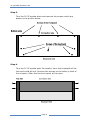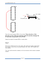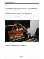
1
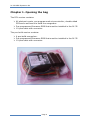
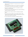
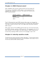
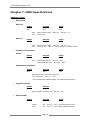
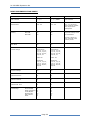
JX-3P MIDI Expansion Kit
Owners manual and installation instructions
Language: English
Manual Version: 2.01
Date: 5 june 2010
Website: http://organix.inque.org
Email: [email protected]
* Roland is a registered trademark of Roland Corp. US
JX-3P MIDI Expansion Kit
Introduction
Thank you for choosing the JX-3P MIDI Expansion Kit from Inque.
The JX-3P MIDI Expansion kit adds more MIDI functionality to the JX-3P
Synthesizer. When you do not have a PG-200 programmer, you can:
Control the JX-3P realtime with standard MIDI-Control messages.
These messages can be sent from a sequencer or a “MIDI-knobbox”.
Load new patches in the JX-3P using a MIDI-file containing MIDIControl messages.
Set the MIDI receive channel to 1, 2, 3 or OMNI.
velocity sensitivity (MIDI input only, not the keyboard)
When you have a PG-200 programmer, you can also:
Use the MIDI input and PG-200 simultaneously.
Use the PG-200 programmer to send out MIDI-Control messages
and record it with a sequencer, or to control another MIDI device.
The ROM firmware that comes with the kit is based on the original
firmware. Therefore the well-beloved authentic sound of your JX-3P will be
still the same after installation and the JX-3P still has all the original
functionalities. The user memory patches will be retained after
installation.*
* Unless you short the backup battery or RAM IC during installation.
Page 2
JX-3P MIDI Expansion Kit
Precautions
Please read the manual carefully before installing the kit!
Caution
The installation of the kit requires opening the JX-3P synthesizer case.
Some knowledge about electronics and soldering is required.
If you don’t have this knowledge and skills, please let a competent person
do the installation for you.
There are high and dangerous voltages inside the JX-3P, please follow the
general safety precautions.
Look out with static electricity. Static electricity could damage the kit and
the JX-3P!
Inque is not responsible for, but not limited to, personal injury, injury of
other people, damage or loss of data caused by the use of the JX-3P MIDI
Expansion kit!
Inque is not associated to Roland Corp. US
Installing and using the kit means that you accept and understand
all of these terms.
Page 3
JX-3P MIDI Expansion Kit
Chapter 1. Opening the bag
The DIY version contains:
All electronic parts, pre-programmed microcontroller, double-sided
PCB and a enclosure to build the mergerbox.
Pre-programmed firmware ROM that must be installed in the JX-3P.
10-pins cable with connector.
The pre-build version contains:
A pre-build mergerbox.
Pre-programmed firmware ROM that must be installed in the JX-3P.
10-pins cable with connector.
Page 4
JX-3P MIDI Expansion Kit
Chapter 2. Assembling the DIY version
This chapter only applies to the DIY version. If you have the prebuild version, you should proceed with chapter 3.
If you have the DIY version then the PCB of the mergerbox needs to be
assembled by you.
Assembling the PCB requires suitable soldering equipment and tools. The
holes and pads on the mergerboard PCB are much smaller than those
used on the DIN Board in the JX-3P. If you do not have experience with
assembling PCBs, please let a competent person do the assembling for
you. Damaged PCB and parts due to incorrect handling cannot be returned
or exchanged.
Always mount the smallest parts first. Do not use too much solder. Never
use aggressive solder liquids like S-39.
Consider the following PCB layout:
Page 5
JX-3P MIDI Expansion Kit
Please follow the following steps:
Mount the resistors:
R1 and R4: 220 Ohm. (Red – Red – Black – Black)
R2 and R3: 1K. (Brown – Black – Black – Brown)
Mount the IC socket (U1). Pay attention to which direction the
socket must mounted. If you mount it the wrong way, it can be
confusing how the IC must be inserted, resulting inserting the wrong
way and a damaged IC.
Mount the LED (D1). Pay attention to which way the anode ‘A’ /
cathode ‘K’ is pointing. The longest leg on the led is the anode. If
you mount it the wrong way, the LED will not work.
Mount the two ceramic capacitors 22 pF (22J) on location C1 and
C2.
Mount the capacitor 100 nF (104R) on location C4.
Mount the crystal 16 MHz on X1. Put the small plastic isolator
between the crystal and the PCB.
Mount the connector P1. Pay attention to how it must be mounted.
Refer to the wire that must be connected to this connector. The
Page 6
JX-3P MIDI Expansion Kit
black wire must correspond to ‘A’, the brown wire to ‘B’… and the
white wire to ‘J’.
Mount the electrolytic capacitor 10 uF on location C3. Pay attention
to the polarity!!! If you mount it the wrong way, it can explode.
Insert the IC ‘Atmega8’ into socket U1. Pay attention to which
direction it must be inserted.
You could use some special PCB Cleaner spray to clean the PCB from
solder flux, and give it a clean look.
Double check your soldering contacts for accidentally unwanted
shorts.
There are six screws provided: two short screws, and four longer
screws. Use the four longer to mount the PCB inside the box. Use to
other two short screws to close the box.
You are finished with the assembling. Proceed with chapter 3.
Page 7
JX-3P MIDI Expansion Kit
Chapter 3. Installation in the JX-3P
This chapter applies to both the DIY and pre-build version and describes
the following actions:
Opening the case of the JX-3P Synthesizer.
Installation of the new firmware ROM.
Modification of the DIN board.
Installation of the mergerbox.
The following things are needed for the installation:
The firmware ROM.
The mergerbox
The 10-pins cable with connector.
Also needed (not included with the kit):
A soldering iron.
Sharp object such as a knife, for removing some PCB connections on
the DIN board.
Other general tools such as screwdrivers and pliers.
An Ohmmeter, to inspect the removed PCB connections for unseen
and unwanted shorts.
Installation steps:
Step 1.
Disconnect the power plug!!
Step 2.
Place the JX-3P on a soft background to be sure that the front panel
will not get scratched when the synthesizer is lying upside down.
Page 8
JX-3P MIDI Expansion Kit
Step 3.
Turn the JX-3P upside down and remove the screws which are
drawn in the picture below.
Step 4.
Turn the JX-3P upside back. Be careful, since the keyboard will be
lose and could fall out. Remove the screws on the sides (a total of
four screws). After this the front panel will be open.
Page 9
JX-3P MIDI Expansion Kit
Step 5.
Rotate the front panel to the rear side. Make sure that there will
be no cable damages.
Remove the keyboard. You do not have to unplug the cables
coming from the keyboard.
From this step there are three actions that should be completed:
Change the firmware ROM.
Modify the DIN board and attach some cables to it.
Install the mergerbox
Page 10
JX-3P MIDI Expansion Kit
Step 6.
You can find the firmware ROM at the lower left side of the mainboard (IC52). The type will be 2764 or 2365 (sometimes with a label on it).
If the firmware ROM is soldered on the mainboard, you need to desolder it
and solder a IC-socked at the location. This action is not described further
in this document.
Carefully remove the old firmware ROM.
Because the new firmware ROM has an larger chip capacity, an extra
(address) line must be added from the CPU to the ROM. This must be
done with pin 26 on both IC’s. Lift up pin 26 from each IC to make it ‘bend
over’ the socket.
Make sure that the bended pin 26 is not making contact again with the
socket or with the metal frame of the keyboard when you put the IC back
into the socket.
Solder a wire on both pins so both IC’s are connected to each other. Make
sure you do not keep the wire too long since it may pick up unwanted
interference.
In some cases the CPU is soldered into the circuitboard. Luckily, it’s not
needed to solder out the CPU or pin since pin 26 is not connected on the
circuitboard. Just solder the wire directly to pin 26 of the CPU on the
circuit board. If the CPU is socketed, take out the CPU from the socket and
bend over pin 26.
Page 11
JX-3P MIDI Expansion Kit
Place the new firmware ROM in the socked. Take attention of the
direction of pin 1! Wrong inserting of the IC could be damage the
IC and other components in the JX-3P!
Keep the original firmware ROM in a safe place.
Step 7.
Remove the DIN board from the upper side of the front panel. Remember
the location of the three connected cables (CN1 JACK, CN2 POWER and
CN3 MAIN).
Tip: you could write the numbers on the connectors with a water-resistant
marker.
Page 12
JX-3P MIDI Expansion Kit
Step 8.
This step describes how to modify the DIN-board. There are two versions:
one with MIDI-Thru and one without MIDI-Thru. Both PCB layouts are
given on the following pages.
The modifications on both boards are the same, only the locations are
different.
Cut the PCB connection at point 1 and 2. Scrap off a small portion of
the coating using a screwdriver or a knife, until you see some
copper. Use an Ohmmeter to make sure that to PCB connection is
really cut in two.
Remove resistor R4 at point 3. Remove also the connection (a wire
bridge) W6 at point 4.
Solder the wires of the 10-pins cable on the PCB at the given
locations in the following PCB layouts. (wires A to J). Some points
require soldering on the PCB wires. Scrap off a small portion of the
coating when needed.
Page 13
JX-3P MIDI Expansion Kit
DIN-Board without MIDI-Thru output
Page 14
JX-3P MIDI Expansion Kit
DIN-Board with MIDI-Thru output
Page 15
JX-3P MIDI Expansion Kit
Step 9.
Verify that all the connections are done correctly. You can bind the wires
together with tape. Place the DIN-board back into the front panel and
attach the three connectors to it.
Connect the 10-pins cable connector to the small plastic box.
Mount the plastic box with double sided tape on the backside of the front
panel, next to the DIN-board. Take attention that the electronics box will
not collide with the power supply when the case is closed.
Close the case and put all screws back in place.
That’s it! You are finished with the installation!
Page 16
JX-3P MIDI Expansion Kit
Chapter 4. MIDI Channel select
After installation the memory protect function will be always off.
The function of the PG200 / MIDI switch on the backside will be
changed after installation of the kit. The switch will function as a
MIDI channel selector.
Switch position
PG200
MIDI channel
1
PG200 protect
MIDI
2
3
The JX-3P selects the (new) MIDI channel after power up. Varying the
setting of the switch while powered up does not change the MIDI channel.
You need to power off and on the JX-3P again after choosing a different
MIDI channel.
After power up the JX-3P, OMNI modus will be off. You can set the JX-3P
into OMNI modus by sending a MIDI controller 125 message to the JX-3P.
After that the JX-3P will listen to all MIDI channels. OMNI modus can be
turned off by sending a MIDI controller 124 message to the JX-3P.
Chapter 5. Velocity sensitive mode
To get into the velocity sensitive mode, hold down ‘7’ while power up the
JX-3P. The keyboard and sequencer will be disabled in this mode. The JX3P will now receive MIDI velocity values.
Page 17
JX-3P MIDI Expansion Kit
Chapter 6. Troubleshooting and FAQ
Q: How do I know that the JX-3P will work in my JX-3P version?
A: Generally, there are two versions of the JX-3P: The non-MIDI-Thru and
the MIDI-Thru version. Both versions are supported by the JX-3P MIDI
expansion kit. The kit has been installed in a variety of JX-3P's in the past,
in all cases without problems.
Q: Is it possible to install this kit in a MKS-30 - since it is the
rackmount module of the JX-3P?
A: No, the kit can be only installed in a JX-3P. There is a MIDI upgrade for
the MKS-30 available at http://analog.no
Q: After installing the JX-3P MIDI Expansion kit, it is possible to
use Sysex to control the JX-3P?
A: No, the JX-3P MIDI Expansion kit uses standard MIDI CC messages
rather than Sysex. Realtime control with CC is MUCH easier to use for
realtime control, and CC is most of the time better implemented in MIDI
Knobboxes and sequencers than Sysex.
Q: Unfortunately I do not have the PG200 programmer. Is it
possible to only install the EPROM with new firmware, instead of
installing both the EPROM and Mergerbox?
A: All of the features of the JX-3P MIDI Expansion kit are implemented in
the mergerbox. Just installing the EPROM will not work, they must both be
installed.
Q: I have a non-working JX-3P, will this kit bring new life in it?
A: No, the kit will not 'resurrect' a non-working JX-3P. It must be installed
in a working-condition JX-3P.
Page 18
JX-3P MIDI Expansion Kit
Q: Why is the LFO Delay not working when I play a note through
MIDI?
A: This is a classic bug from Roland in the original JX-3P firmware. There
is nothing I can do about it, I'm afraid. Fortunately the bug was fixed in
the velocity mode. But in the normal mode, it is still there...
Q: I know that the resolution of the parameters on the PG200 are
8-bit. Since MIDI has only 7-bit, will the resolution of my PG200
also be reduced after installation of the JX-3P MIDI Expansion kit?
A: No, the PG200 still sends 8-bit resolution to the JX-3P. Only the PG200
to MIDI and MIDI to JX-3P signals are 7-bit.
Q: Help!! I have installed the kit and my JX-3P randomly hangs
and after that the LED's are flickering and there is no sound.
A: This is caused due to an incorrectly installed firmware ROM (or a bad
ROM, but this occurs less often). Check if you have bended PIN 26 too far,
resulting in a electrical contact with the metal frame of the keyboard. It is
also possible that PIN 26 is bended not far enough, resulting in a contact
with GND of the socket. It is also possible that the wire between the
EPROM and the CPU is not making a clean contact or causing a short with
some other pin. All such situations will cause problems, and random
behaviors.
Q: My JUNO-106, MKS-30 and GR-700 have had voice-problems
due to a faulty 80017A VCF/VCA module (a.k.a. 'Voicechip').
Should I expect the same troubles with the JX-3P?
A: Fortunately the JX-3P does NOT contain this notorious 80017A module.
The JX-3P uses the IR3109 instead of the 80017A. This is the same filter
chip as found in the JUNO-6/60 and Jupiter synthesizers. Unlike the
80017A, there are no known problems for this chip.
Page 19
JX-3P MIDI Expansion Kit
Chapter 7. MIDI Specifications
MESSAGE TYPES
Note event
Note off
Status
8nH
9nH
kkH:
vvH:
Second
kkH
kkH
Third
vvH
00H
Note number 24H – 60H (36 – 96) C2 – C7
Don’t care
Note on
Status
9nH
kkH:
vvH:
Second
kkH
Third
vvH
Note number 24H – 60H (36 – 96) C2 – C7
Velocity 1H – 7FH (1 – 127). (Only in velocity mode.)
Continuous Controller
Hold 1
Status
BnH
vvH:
Second
40H
Third
vvH
Hold Pedal Off 0H – 3FH (0 – 63)
Hold Pedal On 40H – 7FH (64 – 127)
Synthesizer parameter
Status
BnH
Second
ppH
Third
vvH
ppH: Parameter controller number *
vvH: Value 0H – 7FH (0 – 127)
* see “Parameter address table” for detailed information.
Program change
Status
CnH
Second
ppH
ppH: Program number 0H – 40H (0 – 64)
Pitch bender
Status
EnH
mmH:
nnH:
Second
mmH
Third
nnH
0H – 7FH (0 – 127) Least significant byte
0H – 7FH (0 – 127) Most significant byte
Page 20
JX-3P MIDI Expansion Kit
PARAMETER ADDRESS TABLE
Parameters
CC number
Description
Value – Dec (Hex)
12
(0CH)
Fine Tune
0 – 127 (00H – 7FH)
13
(0DH)
Tune
0 – 127 (00H – 7FH)
14
(0EH)
DCO Envelope Mod.
0 – 127 (00H – 7FH)
15
(0FH)
DCO LFO Mod.
0 – 127 (00H – 7FH)
16
(10H)
Source Mix
0 – 127 (00H – 7FH)
17
(11H)
High Pass
0 – 127 (00H – 7FH)
18
(12H)
Resonance
0 – 127 (00H – 7FH)
19
(13H)
Cutoff Frequency
0 – 127 (00H – 7FH)
20
(14H)
VCF Envelope Mod.
0 – 127 (00H – 7FH)
21
(15H)
VCF LFO Mod.
0 – 127 (00H – 7FH)
22
(16H)
Pitch Follow
0 – 127 (00H – 7FH)
23
(17H)
VCA Level
0 – 127 (00H – 7FH)
24
(18H)
LFO Rate
0 – 127 (00H – 7FH)
25
(19H)
LFO Delay
0 – 127 (00H – 7FH)
26
(1AH)
Attack
0 – 127 (00H – 7FH)
27
(1BH)
Decay
0 – 127 (00H – 7FH)
28
(1CH)
Sustain
0 – 127 (00H – 7FH)
29
(1DH)
Release
0 – 127 (00H – 7FH)
CC number
Description
Value – Dec (Hex)
72
(48H)
DCO-1 Range
0 (00H) 16’, 32 (20H) 8’, 64 (40H) 4’
73
(49H)
DCO-1 Wave
0 (00H) ramp, 32 (20H) pulse, 64 (40H) square
74
(4AH)
DCO-2 Range
0 (00H) 16’, 32 (20H) 8’, 64 (40H) 4’
75
(4BH)
DCO-2 Wave
0 (00H) ramp, 32 (20H) pulse, 64 (40H)
square, 96 (60H) noise
76
(4CH)
DCO-2 Cross Mod.
0 (00H) off, 32 (20H) sync, 64 (40H) metal
77
(4DH)
VCF Envelope Polarity
0 (00H) inverted, 64 (40H) normal
78
(4EH)
VCA Mode
0 (00H) gate, 64 (40H) envelope
79
(4FH)
DCO-2 Envelope Mod.
0 (00H) off, 64 (40H) on
80
(50H)
DCO-2 LFO Mod.
0 (00H) off, 64 (40H) on
81
(51H)
DCO-1 Envelope Mod.
0 (00H) off, 64 (40H) on
82
(52H)
DCO-1 LFO Mod.
0 (00H) off, 64 (40H) on
83
(53H)
LFO Wave
0 (00H) triangle, 32 (20H) square, 64 (40H)
random, 96 (60H) fast random
84
(54H)
DCO Envelope Polarity
0 (00H) inverted, 64 (40H) normal
85
(55H)
Chorus
0 (00H) chorus off, 64 (40H) chorus on
Switches
Page 21
JX-3P MIDI Expansion Kit
MIDI IMPLEMENTATION CHART
Function
Transmitted
Received
Comments
Basic Channel
1, 2, 3
1, 2, 3, OMNI
User defined
Note Number
36 – 96
36 – 96
C2 – C7. Received
note numbers outside
the range will be
transposed.
O
O
O
O
A preset velocity of 64
is transmitted.
Velocity
Note ON
Note OFF
Velocity values are
only received in the
velocity mode.
Pitch Bend
O
O
Control Change
Parameters:
13, 14, 15, 16,
17, 18, 19, 20,
21, 22, 23, 24,
25, 26, 27
Parameters:
13, 14, 15, 16,
17, 18, 19, 20,
21, 22, 23, 24,
25, 26, 27
Hold: 64
Hold: 64
Switches:
72, 73, 74, 75,
76, 77, 78, 79,
80, 81, 82, 83,
84, 85
Switches:
72, 73, 74, 75,
76, 77, 78, 79,
80, 81, 82, 83,
84, 85
Program Change
O
O
System Exclusive
X
X
System Common
X
X
System Real Time
X
X
X
X
X
O
X
X
X
X
X
O
X
X
Aux Message
All Sound Off
Reset Controllers
Local ON/OFF
All Notes Off
Active Sense
Reset
Page 22