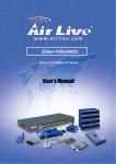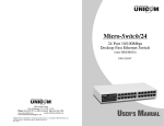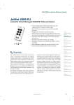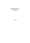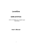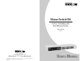
1
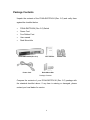
Dyna-Switch/24
24 Port 10/100Base-TX
Fast Ethernet Switch
FEP-31024T-2
rev. 2
908 Canada Court
City of Industry, CA 91748 U.S.A.
Phone: 626.964.7873 or 800.346.6668 Fax: 626.964.7880
www.unicomlink.com
e-mail: [email protected]
©UNICOM 2005. UNICOM and “A Network Systems Solution” are trademarks of UNICOM Electric, Inc.
All rights reserved. Specifications subject to change without notice.
Rev: 09.05
USER’S MANUAL
Introduction
UNICOM’s DYNA-SWITCH/24 (Rev. 2.0) is a 24-port 10/100BASE-TX
Switch that can be used to build high-performance switched workgroup
networks. This switch is a store-and-forward device that offers low latency for
high-speed networking and is targeted at workgroup, department or
backbone computing environments in SME (small, medium enterprise)
businesses.
The DYNA-SWITCH/24 (Rev. 2.0) Switch features a “store-and-forward
“ switching scheme. This allows the switch to auto-learn and store source
address on a 4K-entry MAC address table. It also supports Class of Service
functions. No manual configuration is necessary. The CoS function is
included in the switch firmware and will operate automatically when the
switch is on.
Features
ν
Conforms to IEEE 802.3, 802.3u, and 802.3x
ν
24-port 10/100Base-TX Switch with Auto-MDIX
ν
IEEE 802.3x flow control support
¬
Flow control on full-duplex
¬
Back pressure on half-duplex
ν
N-Way Auto-Negotiation supported
ν
Store-and-Forward switching architecture
ν
No-blocking full wire speed
ν
Embedded 1.25Mbits memory buffer
ν
Support IEEE802.1p Class of Service
ν
4K-entry MAC address table
ν
4.8 Gbps switch back-plane
ν
19” standard size
1
Package Contents
Unpack the contents of the DYNA-SWITCH/24 (Rev. 2.0) and verify them
against the checklist below.
ν
DYNA-SWITCH/24 (Rev. 2.0) Switch
ν
Power Cord
ν
Four Rubber Feet
ν
User manual
ν
Rack Mount kits
DYNA-SWITCH/24 (Rev. 2.0)
Power Cord
User manual
Rubber Feet
Rack-Mount Kits
Package Contents
Compare the contents of your DYNA-SWITCH/24 (Rev. 2.0) package with
the standard checklist above. If any item is missing or damaged, please
contact your local dealer for service.
2
Ethernet Switching Technology
Ethernet Switching Technology has dramatically boosted the total bandwidth
of networks, eliminated congestion problems inherent with Carrier Sense
multiple access with Collision Detection (CSMA/CD) protocol, and greatly
reduced unnecessary transmissions.
This revolutionized networking. First, by allowing two-way, simultaneous
transmissions over the same port (Full-duplex), which essentially doubled the
bandwidth. Second, by reducing the collision domain to a single switch-port,
which eliminated the need for carrier sensing. Third, by using the
store-and-forward technology’s approach of inspecting each packet to
intercept corrupt or redundant data, switching eliminated unnecessary
transmissions that slow a network. This is accomplished by employing
address learning which replaced the inefficient receiving port.
Auto-negotiation regulates the speed and duplex of each port, based on the
capability of both devices. Flow-control allows transmission from a 100Mbps
node to a 10Mbps node without loss of data. Auto-negotiation and
flow-control may require the disabling of some networking operations
involving legacy equipment. Disabling the auto-negotiation is accomplished
by fixing the speed or duplex of a port.
Ethernet Switching Technology has supplied higher performance at costs
lower than other solutions. Wider bandwidth, no congestion, and the
reduction in traffic is why switching is replacing expensive routers and
inefficient hubs as the ultimate networking solution. Switching brings a whole
new way of thinking to networking.
3
Hardware Description
This section describes the hardware of the DYNA-SWITCH/24 and gives a
physical and functional overview of this Switch.
Physical Dimension
The physical dimension of the DYNA-SWITCH/24 is 440mmx 120 mm x
44mm (L x W x H)
Front Panel
The front panel of the DYNA-SWITCH/24 consists of (24) 10/100Base-TX
RJ-45 ports. The LED Indicators are also located on the front panel of the
Switch.
Front panel of the DYNA-SWITCH/24 (Rev. 2.0)
RJ-45 ports (Auto MDI/MDIX): (24) 10/100Mbps auto-sensing ports for
10Base-T or 100Base-TX device connections.
MDI (Medium Dependent Interface) ports are also called "uplink ports”.
The MDI ports do not cross transmit and receive lines, which is done by the
regular ports (MDI-X ports) that connect to end stations. MDI means
connecting to another Hub or Switch while MDIX means connecting to a
workstation or PC. Therefore, Auto MDI/MDIX means that you can connect
to another Switch or workstation with either crossover or non-crossover
cabling.
4
LED Indicators
The LED Indicators gives real-time information of systematic operation status.
The following table provides descriptions of the LED status.
LED
Status
Description
Powe
Green
Power On
Off
Power is not connected
Green
The port is connecting with the device.
Blinks
The port is receiving or transmitting data.
Off
No device attached.
Orange
The port is operating in Full-duplex mode.
Blinks
Collision of Packets occurs in the port.
r
LK/A
CT
FD/C
OL
Off
No device attached or in half-duplex
mode.
The Descriptions of LED Indicators
5
Rear Panel
The 3-pronged power plug is located at the rear panel of the
DYNA-SWITCH/24 as shown in the figure. The switch will work with AC in the
100-240V AC, 50-60Hz range.
The rear panel of the DYNA-SWITCH/24
Desktop Installation
Set the switch on a sufficiently large flat space with a power outlet nearby.
The surface should be clean, smooth, level and sturdy. Make sure there is
enough clearance around the Switch to allow air circulation and the
attachment of cables and the power cord.
Attaching Rubber Feet
1. Make sure mounting surface on the bottom of the Switch is grease and
dust free.
2. Remove adhesive backing from your Rubber Feet.
3. Apply the Rubber Feet to each corner on the bottom of the Switch. These
footpads can protect the Switch from shock and vibration.
6
Rack-mounted Installation
The DYNA-SWITCH/24 comes with a rack-mounting kit (not a standard
option for this switch) and can be mounted in any EIA standard sized, 19"
rack. The Switch can then be placed in a wiring closet with other equipment.
Perform the following steps to rack mount the switch:
1. Position one bracket to align with the holes on one side of the switch and
secure it with the smaller bracket screws. Then attach the remaining
bracket to the other side of the Switch.
Attach mounting brackets with screws
2. After attached both mounting brackets, position the DYNA-SWITCH/24 in
the rack by lining up the holes in the brackets with the appropriate holes
on the rack. Secure the switch to the rack with a screwdriver and the
rack-mounting screws.
Power On
Connect the power cord to the power socket on the rear panel of the Switch.
The other side of power cord connects to the power outlet. The external
power supplies AC in the 100-240VAC voltage range, frequency 50~60Hz.
Check the power indicator on the front panel to ensure power is properly
supplied.
7
Network Application
This section provides a few samples of network topology in which the switch
is used. The DYNA-SWITCH/24 (Rev. 2.0) is designed to be used as a
segment switch. With its large address table (4K MAC address) and high
performance, it is ideal for interconnecting networking segments.
PC, workstations, and servers can communicate with each other by directly
connecting with the DYNA-SWITCH/24. The switch automatically learns
nodes address, which are subsequently used to filter and forward all traffic
based on the destination address.
By using any port as an Uplink port, the Switch can connect with another
switch or hub. This connects each of your small-switched workgroups to form
a larger switched network.
8
Small Workgroup
The DYNA-SWITCH/24 can be used as a standalone switch to which
personal computers, servers, or a printer server are directly connected to
form a small workgroup.
Small Workgroup Application
9
Segment Bridge
In enterprise networks where large data broadcasts are constantly processed,
this switch is an ideal way for departmental users to connect to the corporate
backbone.
In the illustration below, two Ethernet switches, with PCs, a print server, and
a local server attached, are connected to the DYNA-SWITCH/24. Each
device in this network can communicate with the others through the
DYNA-SWITCH/24. Connecting servers to the Switch allows other users to
access the server’s data.
Department Bridge Application
10
Technical Specifications
This section provides the specifications of the DYNA-SWITCH/24.
IEEE 802.3 10Base-T Ethernet,
IEEE 802.3u 100Base-TX Fast Ethernet
Standard
IEEE802.3x Flow Control and
Back-pressure
IEEE802.1p Class of Service
Technology
Store and Forward switching architecture
Protocol
CSMA/CD
Transfer Rate
14,880 pps per Ethernet port
148,800 pps per Fast Ethernet port
MAC address
4K Mac address table
LED Indicators
Per port: Link/Activity, Full duplex/Collision
Per unit: Power
10Base-T: 2-pair UTP/STP Cat. 3, 4, 5
cable
Network Cable
EIA/TIA-568 100-ohm (100m)
100Base-TX: 2-pair UTP/STP Cat. 5 cable
EIA/TIA-568 100-ohm (100m)
Back-plane
Transfer packet
size
Dimension
Memory Buffer
4.8Gbps
64 to 1536Bytes
440mmx 120 mm x 44mm (L x W x H)
19" size
1.5Mbits
2 Queues per port for IEEE 802.1p class of
service and support for IEEE802.1Q VLAN
Class of Service
tag based priority rule. It will recognize 3
bits of precedence carried by the VLAN tag
and map it to the specified priority queue.
11
The packet with a 0~3 precedence value
will flow to the low queue and 4~7 valued
packets will flow to the high queue. It also
supports weight round ration for high and
low queue. The rate is 4:1 (4 high queue
packets then 1 low queue packet)
[Note] The CoS function is included in the
switch firmware and will operate
automatically when the switch is on.
Storage Temp.
-10ºC to 70ºC (-40ºF to 158ºF)
Operational
0ºC to 45ºC (32ºF to 113ºF)
Temp.
Operational
Humidity
10% to 90% (Non-condensing)
Power Supply
100-240 VAC, 50~60Hz
Power
Consumption
10.3 Watts (maximum)
EMI & Safety
FCC Class A, CE, UL& cUL, CE/EN60950
12
Dyna-Switch/24
24 Port 10/100Base-TX
Fast Ethernet Switch
FEP-31024T-2
rev. 2
908 Canada Court
City of Industry, CA 91748 U.S.A.
Phone: 626.964.7873 or 800.346.6668 Fax: 626.964.7880
www.unicomlink.com
e-mail: [email protected]
©UNICOM 2005. UNICOM and “A Network Systems Solution” are trademarks of UNICOM Electric, Inc.
All rights reserved. Specifications subject to change without notice.
Rev: 09.05
USER’S MANUAL