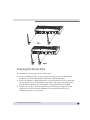
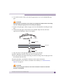
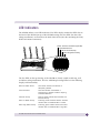
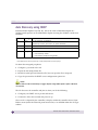
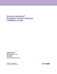
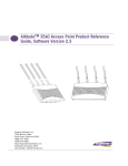
1
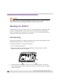
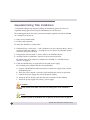
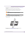
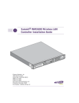
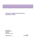
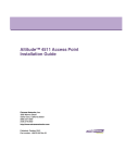
Altitude™ 3510 Access Point
Installation Guide
Extreme Networks, Inc.
3585 Monroe Street
Santa Clara, California 95051
(888) 257-3000
(408) 579-2800
http://www.extremenetworks.com
Published: December 2009
Part Number: 100348-00 Rev 01
AccessAdapt, Alpine, Altitude, BlackDiamond, EPICenter, ExtremeWorks Essentials, Ethernet
Everywhere, Extreme Enabled, Extreme Ethernet Everywhere, Extreme Networks, Extreme
Standby Router Protocol, Extreme Turbodrive, Extreme Velocity, ExtremeWare, ExtremeWorks,
ExtremeXOS, Go Purple Extreme Solution, ExtremeXOS ScreenPlay, ReachNXT, Sentriant,
ServiceWatch, Summit, SummitStack, Triumph, Unified Access Architecture, Unified Access RF
Manager, UniStack, the Extreme Networks logo, the Alpine logo, the BlackDiamond logo, the
Extreme Turbodrive logo, the Summit logos, and the Powered by ExtremeXOS logo are
trademarks or registered trademarks of Extreme Networks, Inc. or its subsidiaries in the United
States and/or other countries.
sFlow is a registered trademark of InMon Corporation.
Specifications are subject to change without notice.
All other registered trademarks, trademarks, and service marks are property of their respective
owners.
© 2009 Extreme Networks, Inc. All Rights Reserved.
2
2
Altitude 3510 Access Point Installation Guide
Altitude 3510 Access Point Installation Guide
Table of Contents
Chapter 1: Introduction............................................................................................. 5
Document Conventions ........................................................................................ 6
Warnings............................................................................................................ 6
Site Preparation.................................................................................................. 7
Chapter 2: AP3510 Specifications ............................................................................ 9
Physical Characteristics....................................................................................... 9
Electrical Characteristics ..................................................................................... 9
Radio Characteristics ........................................................................................ 10
Chapter 3: Hardware Installation............................................................................. 11
Precautions ...................................................................................................... 11
Package Contents ............................................................................................. 11
AP3510 Placement........................................................................................... 12
AP3510 Antenna Options ............................................................................ 12
Powering the Access Point ........................................................................... 13
Mounting the AP3510....................................................................................... 14
Desk Mounting ........................................................................................... 14
Wall Mounting ............................................................................................ 16
Suspended Ceiling T-Bar Installations ........................................................... 18
Above the Ceiling (Plenum) Installations ....................................................... 20
LED Indicators.................................................................................................. 23
Chapter 4: Basic AP3510 Configuration .................................................................. 25
Configuring Initial Settings ................................................................................ 25
Establishing Basic AP Connectivity ..................................................................... 25
Auto Discovery using DHCP.......................................................................... 26
Where to Go From Here?.................................................................................... 27
Chapter 5: Regulatory Compliance .......................................................................... 29
Country Approvals ............................................................................................. 29
Health and Safety Recommendations.................................................................. 29
Warnings for the use of Wireless Devices ....................................................... 29
Potentially Hazardous Atmospheres .............................................................. 30
Altitude 3510 Access Point Installation Guide
3
Safety in Hospitals ...................................................................................... 30
RF Exposure Guidelines..................................................................................... 30
Safety Information ...................................................................................... 30
Reducing RF Exposure—Use Properly ........................................................... 30
Remote and Standalone Antenna Configurations ............................................ 30
Power Supply ................................................................................................... 31
Wireless Devices - Countries .............................................................................. 31
Country Selection........................................................................................ 31
United States ................................................................................................... 32
FCC ........................................................................................................... 33
Radio Frequency Interference Statements................................................ 33
Radio Transmitters (Part 15) .................................................................. 33
Canada ............................................................................................................ 34
Radio Frequency Interference Statement ....................................................... 34
Radio Transmitters ...................................................................................... 34
European Economic Area (EEA).......................................................................... 35
CE Marking ................................................................................................ 35
Statement of Compliance............................................................................. 36
Declaration of Conformity in Languages of the European Community................ 37
New Member States requirements of Declaration of Conformity ....................... 38
RF safety distance ...................................................................................... 38
Conditions of use in the European community ............................................... 38
Israel ............................................................................................................... 40
Other Countries ................................................................................................ 40
Optional 3rd party external antennas............................................................. 41
Chapter 6: Waste Electrical and Electronic Equipment (WEEE) ................................. 43
Chapter 7: Customer Support .................................................................................. 45
Registration...................................................................................................... 45
Documentation ................................................................................................. 45
4
Altitude 3510 Access Point Installation Guide
1
Introduction
The Extreme Networks® Altitude™ 3510 Access Point (AP) provides a bridge between
Ethernet wired LANs or WANs and wireless networks. It provides connectivity between
Ethernet wired networks and radio-equipped mobile units (MUs).
The AP3510 provides a maximum 54Mbps data transfer rate via each radio. It monitors
Ethernet traffic and forwards appropriate Ethernet messages to MUs over the network.
It also monitors MU radio traffic and forwards MU packets to the Ethernet LAN.
An AP3510 can be adopted, configured and managed from a wireless controller. The
management of the AP3510 is conducted by a controller, only after the AP3510 connects
to a Summit® WM3600 or Summit WM3700 model controller and receives its
configuration.
The Extreme Networks AP3510 Access Point comes with a dual 802.11a+g radio and
external antenna. The AP model number is based on the regulatory domain which is
determined by the country of use:
Part Number
Model Number
Regulatory Domain
15720
AP3510-US
For use in the US only
15721
AP3510-ROW
For use in Europe & Rest of World (RoW)
15723
AP3510-IL
For use in Israel only
The following power adapters must be used with the above access points if PoE is not
chosen as the power source:
Part Number
Model
15728
Power Supply-Altitude 3510 (for use only with AP3510 access point)
If new to the AP3510 and access point technology, refer to the Altitude 35x0 Access Point
Product Reference Guide to familiarize yourself with access point technology and the
feature set exclusive to the Extreme Networks AP3510. The guide is available, at
http://www.extremenetworks.com/go/documentation.
Altitude 3510 Access Point Installation Guide
5
Introduction
Document Conventions
The following graphical alerts are used in this document to indicate notable situations
NOTE
Tips, hints, or special requirements that you should take note of.
CAUTION
Care is required. Disregarding a caution can result in data loss or equipment malfunction.
WARNING!
Indicates a condition or procedure that could result in personal injury or equipment damage.
Warnings
6
●
Read all installation instructions and site survey reports, and verify correct
equipment installation before connecting the AP3510 to its power source.
●
Remove jewelry and watches before installing this equipment.
●
Verify that the unit is grounded before connecting it to the power source.
●
Verify that any device connected to this unit is properly wired and grounded.
●
Connect all power cords to a properly wired and grounded electrical circuit.
●
Verify that the electrical circuits have appropriate overload protection.
●
Attach only approved power cords to the device.
●
Verify that the power connector and socket are accessible at all times during the
operation of the equipment.
●
Do not work with power circuits in dimly lit spaces.
●
Do not install this equipment or work with its power circuits during thunderstorms
or other weather conditions that could cause a power surge.
●
Verify there is adequate ventilation around the device, and that ambient
temperatures meet equipment operation specifications.
Altitude 3510 Access Point Installation Guide
Site Preparation
●
Consult your site survey and network analysis reports to determine specific
equipment placement, power drops, and so on.
●
Assign installation responsibility to the appropriate personnel.
●
Identify and document where all installed components are located.
●
Provide a sufficient number of power drops for your equipment.
●
Ensure adequate, dust-free ventilation to all installed equipment.
●
Identify and prepare Ethernet and console port connections.
●
Verify that cable lengths are within the maximum allowable distances for optimal
signal transmission.
Altitude 3510 Access Point Installation Guide
7
Introduction
8
Altitude 3510 Access Point Installation Guide
2
AP3510 Specifications
Physical Characteristics
The AP3510 has the following physical characteristics:
Dimensions
5.32 inches long x 9.45 inches wide x 1.77 inches thick.
135 mm long x 240 mm wide x 45 mm thick.
Housing
Metal, plenum-rated housing (UL2043)
Weight
1.95 lbs/0.88 Kg
Operating
Temperature
-4°F to 122°F / -20°C to 50°C
Storage
Temperature
-40°F to 158°F / -40°C to 70°C
Altitude
8,000 feet/2438m @ 28°F / 28°C (operating)
15,000 feet/4572m @ 53°F / 12°C (storage)
Vibration
Vibration to withstand .02g/Hz, random, sine, 20-2k Hz
Humidity
5 to 95% (operating) 5 to 85% (storage)
Electrostatic
Discharge
15kV (air)
8kV (contact)
Drop
Bench drop 36 inches to concrete (excluding side with connectors)
Electrical Characteristics
The AP3510 has the following input power requirements:
Nominal Operating Voltage
48V DC (Nom)
Nominal Operating Current
250mA @ 48V DC PoE (802.3af compatible)
Altitude 3510 Access Point Installation Guide
9
AP3510 Specifications
Radio Characteristics
The AP3510 has the following radio characteristics. See the datasheet for additional
radio details. The following are radio capabilities. Actual operating power, channels /
frequencies are determined by unique regulatory rules for each country certified. See
http://www.extremenetworks.com/go/rfcertification.htm for a list of countries certified. See
“Regulatory Compliance” on page 29 for additional regulatory information.
Transmit Power
Operating
Channels
802.11b/g
19 dBm +/19 dBm +/18 dBm +/17 dBm +/16 dBm +/-
1
1
1
1
1
dBm
dBm
dBm
dBm
dBm
@
@
@
@
@
1, 2, 5.5, 11 Mbps
6 and 9 Mbps
12 and 18 Mbps
24 and 36 Mbps
48 and 54 Mbps
802.11a
17 dBm +/16 dBm +/15 dBm +/14 dBm +/-
1
1
1
1
dBm
dBm
dBm
dBm
@
@
@
@
6 and 9 Mbps
12 and 18 Mbps
24 and 36 Mbps
48 and 54 Mbps
802.11a radio - Channels 35-165 (4920-5850 MHz)
802.11b/g radio - Channels 1-13 (2412-2472 MHz)
802.11b/g radio - Channel 14 (2484 MHz Japan only)
Actual operating frequencies depend on regulatory rules
and certification agencies.
Radio Data Rates
802.11a radio 6, 9, 12, 18, 24, 36, 48, and 54 Mbit/Sec
802.11g radio 6, 9, 12, 18, 24, 36, 48, and 54 Mbit/Sec
802.11b radio 1, 2, 5.5, 11 Mbps
Wireless Medium
10
Direct Sequence Spread Spectrum (DSSS)
Orthogonal Frequency Division Multiplexing (OFDM)
Altitude 3510 Access Point Installation Guide
3
Hardware Installation
An AP3510 installation includes mounting the AP3510 on a table-top, wall, ceiling T-bar
or above the ceiling orientation, connecting the AP3510 to the network (LAN or WAN
port connection), connecting antennas and applying power. Installation procedures vary
for different environments.
Precautions
Before installing the AP3510 verify the following:
●
Do not install in wet or dusty areas without additional protection. Contact an
Extreme Networks representative for more information.
●
Verify the environment has a continuous temperature range between -20° C to 50° C.
Package Contents
Check package contents for the correct model AP3510 depending on your country of
application and applicable AP3510 accessories. Each available configuration (at a
minimum), contains:
●
AP3510 Dual 802.11a+g radio, external antenna. The part number is dependent on
the regulatory domain:
Part Number
Model Number
Regulatory Domain
15720
AP3510-US
For use in the US only
15721
AP3510-ROW
For use in Europe & Rest of World (RoW)
15723
AP3510-IL
For use in Israel only
●
Altitude 3510 Access Point Installation Guide
●
Accessories Bag (4 rubber feet for desk mounting and an LED light pipe and badge
with label for above the ceiling installations)
Verify the model indicated on the bottom of the AP3510 is correct. Contact the Extreme
Networks Support Center to report missing or improperly functioning items.
Altitude 3510 Access Point Installation Guide
11
Hardware Installation
AP3510 Placement
For optimal performance, install the AP3510 away from transformers, heavy-duty
motors, fluorescent lights, microwave ovens, refrigerators and other industrial
equipment. Signal loss can occur when metal, concrete, walls or floors block
transmission. Install the AP3510 in open areas or add access points as needed to
improve coverage.
Place the AP3510 using the following guidelines:
●
Install the AP3510 at an ideal height of 10 feet from the ground.
●
Orient the AP3510 antenna vertically for best reception.
●
Point the AP3510 antenna(s) downward if attaching to the ceiling.
Extreme Networks recommends conducting a site survey to define and document radio
interference obstacles before installing the AP3510 to maximize its radio coverage area.
AP3510 Antenna Options
Both Radio 1 and Radio 2 require one antenna and can optimally use two antennas per
radio. Two antennas per radio provides diversity that can improve performance and
signal reception. The AP3510 is shipped with four dualband, omnidriectional paddle
antennas for indoor use. The nominal net gain for the antenna is 3.0dBi on a 2.4 GHz
radio and 4.0dBi on a 5GHz radio. For more information on the antenna options
available to the AP3510, refer to the Altitude™ 35xx/45xx AP Antenna Selection Guide
available from http://www.extremenetworks.com/go/documentation.
NOTE
On an AP3510, Radio 1 refers to the AP3510’s 2.4 GHz radio and Radio 2 refers to the AP3510
5.2 GHz radio. However, there could be some cases where an AP3510 is performing a Rogue AP
detector function. In this scenario, the AP3510 is receiving in either 2.4 GHz or 5.2 GHz over the
Radio 1 or Radio 2 antennas depending on which radio is selected for the scan.
Antenna connectors for Radio 1 are located in a different location from the Radio 2
antenna connectors.
12
Altitude 3510 Access Point Installation Guide
Powering the Access Point
The AP3510 can receive power in one of three ways:
●
Power over Ethernet (PoE) - If your network is already set up with PoE (802.3af
compliant), attach the LAN Ethernet cable to the AP3510’s LAN port.
●
Power over Ethernet: Adding PoE injector - If your network is not set up with PoE,
you can provide power to the Ethernet cable with a PoE injector. The PoE injector
must be 802.3af compliant. The PoE injector is not provided with the AP3510.
●
Power by AC adaptor - Extreme Network's 48V AC-DC power supply (Part No.
15728) can be used to power the AP3510. It is not included in the kit and is
orderable separately as an accessory.
Altitude 3510 Access Point Installation Guide
13
Hardware Installation
CAUTION
The AP3510 supports any standards-based 802.3af compliant power source. However, using the
wrong solution could severely damage the AP3510 and void the product warranty.
Mounting the AP3510
The AP3510 can rest on a flat surface, attach to a wall, mount under a suspended T-Bar
or above a ceiling (plenum or attic). Choose one of the following mounting options
based on the physical environment of the coverage area. Do not mount the AP3510 in a
location that has not been approved in a site survey.
Desk Mounting
The desk mount option uses rubber feet (found in the accessories bag shipped with the
AP3510) allowing the unit to sit on most flat surfaces.
To install the AP3510 in a desk mount orientation:
1 Turn the AP3510 upside down.
2 Remove the backings from the four (4) rubber feet and attach them to the four
rubber feet recess areas on the AP3510.
3 Attach the Radio 1 and Radio 2 antennas to their correct connectors. The antenna
covers will most likely need to be removed to orient the antenna upward in a typical
desktop installation.
14
Altitude 3510 Access Point Installation Guide
For more information on the antenna options available to the AP3510, refer to the
Altitude™ 35xx/45xx AP Antenna Selection Guide available from
http://www.extremenetworks.com/go/documentation.
CAUTION
Ensure you are placing the antennas on the correct connectors to ensure the successful operation
of the AP3510.
4 Cable the AP3510 using either an 802.3af standard power source or an approved line
cord and power supply.
For standard power adapter and line cord installations:
a Connect an RJ-45 Ethernet cable between the network data supply (host) and the
AP3510 LAN port.
b Verify the power adapter is correctly rated according the country of operation.
c
Connect the power supply line cord to the power adapter.
d Attach the power adapter cable into the power connector on the AP3510.
e Attach the power supply line cord to a power supply
CAUTION
Do not actually connect to the power source until the cabling portion of the installation is
complete.
NOTE
For other options to power up the AP3510, refer to “Powering the Access Point” on page 13.
5 Verify the behavior of the AP3510 LEDs. For more information, see “LED Indicators”
on page 23.
6 Return the AP3510 to an upright position and place it in the location you wish it to
operate. Ensure the AP3510 is sitting evenly on all four rubber feet.
7 The AP3510 is ready to configure. For information on basic AP3510 device
configuration, see “Basic AP3510 Configuration” on page 25.
Altitude 3510 Access Point Installation Guide
15
Hardware Installation
Wall Mounting
Wall mounting requires hanging the AP3510 along its width (or length) using the pair
of slots on the bottom of the unit and using the AP3510 itself as a mounting template
for the screws.
CAUTION
An AP3510 should be wall mounted to concrete or plaster-wall-board (dry wall) only. Do not wall
mount an AP3510 to combustible surfaces.
●
The mounting hardware and tools (customer provided) required to install the
AP3510 on a wall consists of:
●
Two Phillips pan head self-tapping screws
(ANSI Standard) #6-18 X 0.875in. Type A or AB Self-Tapping screw, or
(ANSI Standard Metric) M3.5 X 0.6 X 20mm Type D Self-Tapping screw
●
Two wall anchors
●
Security cable (optional)
To mount the AP3510 on a wall:
1 Orient the AP3510 on the or ceiling by its width or length.
2 Using the arrows on one edge of the case as guides, move the edge to the midline of
the mounting area and mark points on the midline for the screws.
3 At each point, drill a hole in the wall, insert an anchor, screw into the anchor the
wall mounting screw and stop when there is 1mm between the screw head and the
wall.
If pre-drilling a hole, the recommended hole size is 2.8mm (0.11in.) if the screws are
going directly into the wall and 6mm (0.23in.) if wall anchors are being used.
4 If required, install and attach a security cable to the AP3510 lock port.
5 Attach the Radio 1 and Radio 2 antennas to their correct connectors.
6 For information on the antennas available to the AP3510, see “AP3510 Antenna
Options” on page 12.
7 Place the large corner of each of the mount slots over the screw heads.
8 Slide the AP3510 down along the mounting surface to hang the mount slots on the
screw heads.
16
Altitude 3510 Access Point Installation Guide
CAUTION
Ensure you are placing the antennas on the correct connectors to ensure the successful
operation of the AP3510.
NOTE
The AP3510 must be mounted with the RJ45 cable connector oriented upwards to ensure
proper operation.
9 Cable the AP3510 using an approved line cord and power supply.
For standard power adapter and line cord installations:
a Connect a RJ-45 Ethernet cable between the network data supply (host) and the
AP3510 LAN port.
b Verify the power adapter is correctly rated according the country of operation.
c
Connect the power supply line cord to the power adapter.
d Attach the power adapter cable into the power connector on the AP3510.
e Attach the power supply line cord to a power supply.
CAUTION
Do not actually connect to the power source until the cabling portion of the installation is
complete.
NOTE
For other options to power up the AP3510, refer to “Powering the Access Point” on page 13.
10 Verify the behavior of the AP3510 LEDs. For more information, see “LED Indicators”
on page 23.
11 The AP3510 is ready to configure. For information on basic AP3510 device
configuration, see “Basic AP3510 Configuration” on page 25.
Altitude 3510 Access Point Installation Guide
17
Hardware Installation
Suspended Ceiling T-Bar Installations
A suspended ceiling mount requires holding the AP3510 up against the T-bar of a
suspended ceiling grid and twisting the AP3510 chassis onto the T-bar.
The mounting hardware and tools (customer provided) required to install the AP3510
on a ceiling T-bar consists of:
●
Safety wire (recommended)
●
Security cable (optional)
To install the AP3510 on a ceiling T-bar:
1 If required, loop a safety wire — with a diameter of at least 1.01 mm (.04 in.), but no
more than 0.158 mm (.0625 in.) — through the tie post (above the AP3510’s console
connector) and secure the loop.
2 If required, install and attach a security cable to the AP3510 lock port.
3 Attach the Radio 1 and Radio 2 antennas to their correct connectors.
For information on the antennas available to the AP3510, see “AP3510 Antenna
Options” on page 12.
4 Cable the AP3510 using an approved line cord and power supply.
For standard power adapter and line cord installations:
a Connect a RJ-45 Ethernet cable between the network data supply (host) and the
AP3510 LAN port.
b Verify the power adapter is correctly rated according the country of operation.
c
Connect the power supply line cord to the power adapter.
d Attach the power adapter cable into the power connector on the AP3510.
e Attach the power supply line cord to a power supply.
CAUTION
Do not actually connect to the power source until the cabling portion of the installation is
complete.
NOTE
For other options to power up the AP3510, refer to “Powering the Access Point” on page 13.
18
Altitude 3510 Access Point Installation Guide
5 Verify the behavior of the AP3510 LEDs. For more information, see “LED Indicators”
on page 23.
6 Align the bottom of the ceiling T-bar with the back of the AP3510.
7 Orient the AP3510 chassis by its length and the length of the ceiling T-bar.
8 Rotate the AP3510 chassis 45 degrees clockwise, or about 10 o’clock.
CAUTION
Push the back of the AP3510 chassis on to the bottom of the ceiling T-bar.
CAUTION
Ensure the safety wire and cabling used in the T-Bar AP3510 installation is securely fastened
to the building structure in order to provide a safe operating environment.
9 Rotate the AP3510 chassis 45 degrees counter-clockwise. The clips click as they
fasten to the T-bar.
10 The AP3510 is ready to configure. For information on basic AP3510 device
configuration, see “Basic AP3510 Configuration” on page 25.
Altitude 3510 Access Point Installation Guide
19
Hardware Installation
Above the Ceiling (Plenum) Installations
An AP3510 above the ceiling installation requires placing the AP3510 above a
suspended ceiling and installing the provided light pipe under the ceiling tile for
viewing the rear panel status LEDs of the unit. An above the ceiling AP3510 installation
enables installations compliant with drop ceilings, suspended ceilings and industry
standard tiles from .625 to .75 inches thick.
NOTE
The AP3510 is Plenum rated to UL2043 and NEC1999 for above the ceiling installations.
CAUTION
Extreme Networks does not recommend mounting the AP3510 directly to any suspended ceiling
tile with a thickness less than 12.7mm (0.5in.) or a suspended ceiling tile with an unsupported
span greater than 660mm (26in.). Extreme Networks strongly recommends fitting the AP3510
with a safety wire suitable for supporting the weight of the device. The safety wire should be a
standard ceiling suspension cable or equivalent steel wire between 1.59mm (.062in.) and 2.5mm
(.10in.) in diameter.
The mounting hardware required to install the AP3510 above a ceiling consists of:
●
Light pipe
●
Badge for light pipe
●
Decal for badge
●
Safety wire (strongly recommended)
●
Security cable (optional)
To install the AP3510 above a ceiling:
1 If possible, remove the adjacent ceiling tile from its frame and place it aside.
2 If required, install a safety wire, between 1.5mm (.06in.) and 2.5mm (.10in.) in
diameter, in the ceiling space.
3 If required, install and attach a security cable to the AP3510’s lock port.
4 Mark a point on the finished side of the tile where the light pipe is to be located.
5 Create a light pipe path hole in the target position on the ceiling tile.
20
Altitude 3510 Access Point Installation Guide
6 Use a drill to make a hole in the tile the approximate size of the AP3510 LED light
pipe.
CAUTION
Extreme Networks recommends care be taken not to damage the finished surface of the ceiling
tile when creating the light pipe hole and installing the light pipe.
7 Remove the light pipe’s rubber stopper (from the AP3510) before installing the light
pipe.
8 Connect the light pipe to the bottom of the AP3510. Align the tabs and rotate
approximately 90 degrees. Do not over tighten.
.
Light Pipe
Ceiling Tile
Decal
Badge
9 Snap the clips on the light pipe into the bottom of the AP3510.
10 Fit the light pipe into hole in the tile from its unfinished side.
11 Place the decal on the back of the badge and slide the badge onto the light pipe from
the finished side of the tile.
12 Attach the Radio 1 and Radio 2 antennas to their correct connectors.
13 For information on the antennas available to the AP3510, see “AP3510 Antenna
Options” on page 12.
CAUTION
Ensure you are placing the antennas on the correct connectors to ensure the successful
operation of the AP3510.
Altitude 3510 Access Point Installation Guide
21
Hardware Installation
14 Attach safety wire (if used) to the AP3510 safety wire tie point or security cable (if
used) to the AP3510’s lock port.
15 Align the ceiling tile into its former ceiling space.
16 Cable the AP3510 using an approved line cord and power supply.
For standard power adapter and line cord installations:
a Connect an RJ-45 Ethernet cable between the network data supply (host) and the
AP3510 LAN port.
b Verify the power adapter is correctly rated according the country of operation.
c
Connect the power supply line cord to the power adapter.
d Attach the power adapter cable into the power connector on the AP3510.
e Attach the power supply line cord to a power supply.
CAUTION
Do not actually connect to the power source until the cabling portion of the installation is
complete.
NOTE
For other options to power up the AP3510, refer to “Powering the Access Point” on page 13.
17 Verify the behavior of the AP3510 LED light pipe. For more information, see
“LED Indicators” on page 23.
18 Place the ceiling tile back in its frame and verify it is secure.
19 The AP3510 is ready to configure. For information on basic AP3510 device
configuration, see “Basic AP3510 Configuration” on page 25.
22
Altitude 3510 Access Point Installation Guide
LED Indicators
The AP3510 utilizes seven LED indicators. Five LEDs display within four LED slots on
the front of the AP3510 (on top of the AP3510 housing) and two LEDs (for above the
ceiling installations) are located on the back of the device (the side containing the LAN,
WAN and antenna connectors).
0OWERAND%RROR#ONDITIONS3PLIT,%$
$ATA/VER%THERNET
A2ADIO!CTIVITY
BG2ADIO!CTIVITY
The five LEDs on the top housing of the AP3510 are clearly visible in table-top, wall
and below ceiling installations. The five AP3510 top housing LEDs have the following
display and functionality:
Boot and Power Status
Solid white indicates the AP3510 is
adequately powered.
Error Conditions
Solid red indicates the AP3510 is
experiencing a problem condition requiring
immediate attention.
Ethernet Activity
Flashing white indicates data transfers and
Ethernet activity.
802.11a Radio Activity
Flickering amber indicates beacons and data
transfers over the AP3510 802.11a radio.
802.11b/g Radio Activity
Flickering green indicates beacons and data
transfers over the AP3510 802.11b/g radio.
Altitude 3510 Access Point Installation Guide
23
Hardware Installation
The LEDs on the rear of the AP3510 are viewed using a single (customer installed)
extended light pipe, adjusted as required to suit above the ceiling installations. The
LEDs displayed using the light pipe have the following color display and functionality:
Boot and Power Status
Solid white indicates the AP3510 is adequately
powered.
Error Conditions
Solid red indicates the AP3510 is experiencing a
problem condition requiring immediate attention.
Blinking red indicates the AP3510 Rogue AP
Detection feature has located a rogue device.
24
Altitude 3510 Access Point Installation Guide
4
Basic AP3510 Configuration
Configuring Initial Settings
An AP3510 needs settings defined to discover an available controller and register with
it. It is through this controller registration that the AP3510 receives its configuration. If
the AP’s link to the controller fails, the AP continues to operate using the last valid
configuration until its link is reestablished and a new configuration is pushed down
from the controller.
Only WLAN, VLAN extension and radio configuration items are defined for the AP by
its connected controller. None of the other AP3510 configuration items (RADIUS, DHCP,
NAT, Firewall, and so forth) are configurable from the connected controller. See the
Altitude 35x0 Access Point Product Reference Guide for further configuration of these
parameters.
Ensure that the AP image and the controller image are compatible. Refer to release
notes for the AP firmware compatibility matrix. Refer to product documentation for
how to upgrade the AP firmware.
Establishing Basic AP Connectivity
This section defines the steps required to establish basic AP connectivity with an
Extreme Networks Summit WM3x00 model controller.
Prerequisites for connecting an AP3510 to a controller include:
●
Ensure that your controller has an appropriate AP capacity license.
●
Ensure that the controller is up and running on the network and is reachable from
the network on which the AP is installed.
●
Refer to the controller installation guide and Summit WM3000 Series Controller System
Reference Guide for details.
Altitude 3510 Access Point Installation Guide
25
Basic AP3510 Configuration
Auto Discovery using DHCP
Extended Global Options 189, 190, 191, 192 can be used or Embedded Option 43 Vendor Specific options can be embedded in Option 43 using the AP3510’s vendor class
identifier:
Option
Data Type Value
189
String
190
String
191
String
AP3510 Encryption IPSec Passphrase (Hashed) **
192
String
AP3510 controller discovery mode
List of Controller IP addresses
(separate by comma, semi-colon, or space delimited)
<FQDN (Fully Qualified Domain Name) of the Wireless Controller>
1 = auto discovery enable
2 = auto discover enabled (using IPSec)
** The AP3510 uses an encryption key to hash passphrases and security keys.
To obtain the encrypted passphrase:
1 Configure a password in the AP.
2 Export the AP configuration file.
3 Read the hashed password from the file (You can open the file in notepad).
4 Copy the password to the DHCP server configuration option 191.
NOTE
Options 189 and 192 are mandatory to trigger adoption using DHCP options. Option 189 alone
will not work.
The AP discovers the controller and joins it when you do the following:
1 Configure your DHCP server per the table above.
2 Connect the AP to the network and power it up.
Once an AP is adopted by the controller, it displays within the controller Access Point
Radios screen (under the Network parent menu item) as an AP3510 within the AP Type
column.
26
Altitude 3510 Access Point Installation Guide
Where to Go From Here?
Once basic connectivity has been verified, the AP3510 can be fully configured to meet
the needs of the network and the users it supports. For more details refer to the AP35x0 Access Point Product Reference Guide. The guide is available on the Extreme
Networks Web site, at http://www.extremenetworks.com/go/documentation.
Altitude 3510 Access Point Installation Guide
27
Basic AP3510 Configuration
28
Altitude 3510 Access Point Installation Guide
5
Regulatory Compliance
All Extreme Networks devices are designed to be compliant with rules and regulations
in locations of intended sale and are labeled as required by the authorizing agency. Any
changes or modifications to Extreme Networks equipment, not expressly approved by
Extreme Networks, could void the user's authority to operate the equipment.
The Radio Frequency Output Power will not exceed the maximum allowable limit for
the country of operation when properly installed.
Antennas: Use only the supplied or an approved replacement antenna. Unauthorized
antennas, modifications, or attachments could cause damage and may violate
regulations.
Country Approvals
Regulatory markings and ID numbers have been applied to the device label signifying
the radio (s) are approved for use in the country list located at
http://www.extremenetworks.com/go/rfcertification.htm This list of countries is extensive and
includes but is not limited to: United States, Canada, Australia, Japan, Europe and
China.
Operation of the device without regulatory approval is illegal.
Health and Safety Recommendations
Warnings for the use of Wireless Devices
Please observe all warning notices with regard to the usage of wireless devices.
Altitude 3510 Access Point Installation Guide
29
Regulatory Compliance
Potentially Hazardous Atmospheres
You are reminded of the need to observe restrictions on the use of radio devices in fuel
depots, chemical plants etc. and areas where the air contains chemicals or particles
(such as grain, dust, or metal powders).
Safety in Hospitals
Wireless devices transmit radio frequency energy and may affect medical electrical
equipment. When installed adjacent to other equipment, it is advised to verify that the
adjacent equipment is not adversely affected.
RF Exposure Guidelines
Safety Information
The device complies with Internationally recognized standards covering human
exposure to electromagnetic fields from radio devices.
Reducing RF Exposure—Use Properly
Only operate the device in accordance with the instructions supplied.
Remote and Standalone Antenna Configurations
To comply with FCC RF exposure requirements, antennas that are mounted externally
at remote locations or operating near users at stand-alone desktop of similar
configurations must operate with a minimum separation distance of 20 cm from all
persons.
30
Altitude 3510 Access Point Installation Guide
Power Supply
The AP3510 can receive power in one of three ways:
1 Power over Ethernet (PoE) - If your network is already set up with PoE (802.3af
compliant), attach the LAN Ethernet cable to the AP3510’s LAN port.
2 Power over Ethernet: Adding PoE injector - If your network is not set up with PoE,
you can provide power to the Ethernet cable with a PoE injector. The PoE injector
must be 802.3af compliant. The PoE injector is not provided with the AP3510.
3 Power by AC adaptor - Extreme Networks 48V AC-DC power supply (Model No.
15728) can be used to power the AP3510. It is not included in the kit and is orderable
separately as an accessory.
If option number 3 is chosen, use only the Extreme Networks 15728 Power SupplyAltitude 3510 adapter. It is pre-approved for use in multiple countries similar to
AP3510. See http://www.extremenetworks.com/go/rfcertification/htm for approved country list.
If the country is not listed Option number 2 should be used.
Option number 2 suggests a pre-approved power injector certified as a 802.3af
compliant PoE injector is used certified for Safety & EMC within country of interest. It
shall have a minimum output power rating of 48V DC, 250mA and have appropriate
power input cord & plug.
NOTE
Use only an Extreme Networks approved power supply. Use of alternative power supply may
invalidate any approval given to this device and may be dangerous if not properly tested and
approved by a local agency.
Wireless Devices - Countries
Country Selection
The Extreme Networks AP3510 Access Point comes with a dual 802.11a+g radio and is
manufactured in 3 different model numbers. The location of installation will determine
the appropriate model number to choose. Due to unique regulatory requirements of
United States and Israel only that country will appear in the country list upon set-up
Altitude 3510 Access Point Installation Guide
31
Regulatory Compliance
for these models. The AP3510-ROW 11abg will list many countries where it is the
professional installer and end users responsibility to properly follow these instructions
to set-up AP.
Part Number
Model Number
Regulatory Domain
15720
AP3510-US
For use in the US only
15721
AP3510-ROW
For use in Europe & Rest of World (RoW)
15723
AP3510-IL
For use in Israel only
Although outdoor use may be allowed and may be restricted to certain frequencies
and/or may require a license for operation, the Altitude AP3510 is intended for indoor
use and must be installed in a proper indoor location. Use the installation utility
provided with the controller software to ensure proper set-up in accordance with all
European spectrum usage rules. Contact local Authority for procedure to follow and
regulatory information. For more details on legal combinations of frequencies, power
levels see http://www.extremenetworks.com/go/rfcertification.htm or contact Extreme Networks.
WARNING!
Select only the country in which you are using the device. Any other selection will make the
operation of this device illegal. The professional installer and end user are responsible to properly
follow all instructions and warning when installing this device.
United States
The Extreme Networks 15720 AP3510-US Access Point is dedicated for use in the
United States under rules of the FCC. Other countries may also use the model if they
agree with FCC operating frequencies and powers applicable to this model.
The use on UNII (Unlicensed National Information Infrastructure) Band 1 5150-5250
MHz is restricted to indoor use only. Any other use will make the operation of this
device illegal. The available channels for 802.11 b/g operation in the US are Channels 1
to 11. The range of channels is limited by firmware.
32
Altitude 3510 Access Point Installation Guide
FCC
Radio Frequency Interference Statements
This equipment has been tested and found to comply with the limits for a Class
B digital device, pursuant to Part 15 of the FCC rules. These limits are designed
to provide reasonable protection against harmful interference in a residential
installation. This equipment generates, uses and can radiate radio frequency
energy and, if not installed and used in accordance with the instructions, may
cause harmful interference to radio communications. However there is no guarantee that
interference will not occur in a particular installation. If this equipment does cause harmful
interference to radio or television reception, which can be determined by turning the equipment
off and on, the user is encouraged to try to correct the interference by one or more of the
following measures:
●
Reorient or relocate the receiving antenna
●
Increase the separation between the equipment and receiver
●
Connect the equipment into an outlet on a circuit different from that to which the
receiver is connected
●
Consult the dealer or an experienced radio/TV technician for help.
Radio Transmitters (Part 15)
This device complies with Part 15 of the FCC Rules. Operation is subject to the
following two conditions: (1) this device may not cause harmful interference, and (2)
this device must accept any interference received, including interference that may cause
undesired operation.
Altitude 3510 Access Point Installation Guide
33
Regulatory Compliance
Canada
Radio Frequency Interference Statement
This Class B digital apparatus complies with Canadian ICES-003.
Cet appareil numérique de la classe B est conforme à la norme NMB-003 du Canada.
Radio Transmitters
This device complies with RSS 210 of Industry & Science Canada. Operation is subject
to the following two conditions: (1) this device may not cause harmful interference and
(2) this device must accept any interference received, including interference that may
cause undesired operation.
To reduce potential radio interference to other users, the antenna type and its gain
should be so chosen that the equivalent isotropically radiated power (EIRP) is not more
than that permitted for successful communication.
This device has been designed to operate with the antennas listed in the Altitude 35xx/
45xx AP Antenna Selection Guide available from
http://www.extremenetworks.com/go/documentation. Antennas not included in this list or
having a gain greater than 13.9dBi (2.4GHz) and 13dBi (5GHz) are strictly prohibited for
use with this device. The required antenna impedance is 50 ohms.
Label Marking: The Term "IC:" before the radio certification signifies that Industry
Canada technical specifications were met.
34
Altitude 3510 Access Point Installation Guide
European Economic Area (EEA)
CE Marking
The Altitude APs are designed for use in the European Union and other countries with
similar regulatory restrictions where the end user or installer is allowed to configure the
Altitude AP for operation by selecting a specific country from a list of countries. Upon
connection to the controller, the software will prompt the user to select a country. After
the country is selected, the controller will set up the Altitude AP with the proper
frequencies and power outputs for that country as required by authorities.
Although outdoor use may be allowed and may be restricted to certain frequencies
and/or may require a license for operation, the Altitude AP3510 is intended for indoor
use and must be installed in a proper indoor location. Use the installation utility
provided with the controller software to ensure proper set-up in accordance with all
European spectrum usage rules. Contact local Authority for procedure to follow and
regulatory information. For more details on legal combinations of frequencies, power
levels see
http://www.extremenetworks.com/go/rfcertification.htm or contact Extreme Networks.
The use of 2.4GHz RLAN’s, for use throughout the EEA includes the following
countries and have the following restrictions:
Europe includes, Austria, Belgium, Bulgaria, Czech Republic, Cyprus, Denmark,
Estonia, Finland, France, Germany, Greece, Hungary, Iceland, Ireland, Italy, Latvia,
Liechtenstein, Lithuania, Luxembourg, Malta, Netherlands, Norway, Poland, Portugal,
Romania, Slovak Republic, Slovenia, Spain, Sweden, Switzerland and the United
Kingdom.
●
Maximum radiated transmit power of 100 mW EIRP in the frequency range 2.400 2.4835 GHz (Channels 1-13).
●
5GHz operation is limited to 5.15 to 5.25 GHz (Channels 36 40, 44 & 48) indoor use
only. The AP3510 does not support ETSI 301 893 V 1.3.1.
●
Antenna use is restricted to those antennas listed in the Altitude 35xx/45xx AP
Antenna Selection Guide.
●
France outside usage, the equipment is restricted to 2.400-2.45 GHz frequency range.
●
Italy & Greece require a user license for outside usage.
Altitude 3510 Access Point Installation Guide
35
Regulatory Compliance
●
Belgium requires notifying the spectrum agency if deploying > 300 meter wireless
links in outdoor public areas and outdoor operation is only permitted using the
2.46 - 2.4835 GHz band: Channel 13.
●
In France, outdoor operation is only permitted using the 2.4 - 2.454 GHz band:
Channels 1 - 7.
Statement of Compliance
Extreme Networks hereby, declares that this device is in compliance
with the essential requirements and other relevant provisions of
Directive 1999/5/EC. A Declaration of Conformity may be obtained from
http://www.extremenetworks.com/go/rfcertification/htm.
NOTE
The Altitude AP3510 is in compliance with the European Directive 2002/95/EC on the restriction
of the use of certain hazardous substances (RoHS) in electrical and electronic equipment and the
European Directive 2002/96/EC (WEEE) on waste electrical and electronic equipment.
36
Altitude 3510 Access Point Installation Guide
Declaration of Conformity in Languages of the European
Community
Altitude 3510 Access Point Installation Guide
37
Regulatory Compliance
New Member States requirements of Declaration of
Conformity
RF safety distance
This access point must be installed to provide a separation distance of at least 25cm
from all persons and must not be co-located or operating in conjunction with another
antenna or transmitter.
Conditions of use in the European community
The Altitude APs with internal and external antennas are designed and intended to be
used indoors. Some EU countries allow outdoor operation with limitations and
restrictions, which are described in this section. It is the responsibility of the end user to
ensure operation in accordance with these rules, frequencies, and transmitter power
output. The Altitude AP must not be operated until properly configured for the
customer's geographic location.
38
Altitude 3510 Access Point Installation Guide
CAUTION
The professional user or installer is responsible to ensure that the Altitude AP is operated
according to channel limitations, indoor / outdoor restrictions, license requirements, and within
power level limits for the current country of operation in accordance with the spectrum usage rules
for compliance with the European R&TTE directive 1999/5/EC.
CAUTION
The Altitude APs with internal and external antennas are designed to be operated only indoors
within all countries of the European Community. Some countries require limited channels of
operation. These restrictions are described in this section.
CAUTION
The Altitude AP is completely configured and managed by the Summit WM Controller connected
to the network. Please follow the instructions in this user guide to properly configure the Altitude
APs.
CAUTION
The Altitude APs require the end user or installer to ensure that they have a valid license prior to
operating the Altitude AP. The license contains the region and the region exposes the country
codes which allow for proper configuration in conformance with European National spectrum usage
laws
CAUTION
There is a default group of settings that each Altitude AP receives when it connects to the
controller. There is the ability to change these settings. The user or installer is responsible to
ensure that each Altitude AP is properly configured.
Altitude 3510 Access Point Installation Guide
39
Regulatory Compliance
CAUTION
The software within the controller will automatically limit the allowable channels and output power
determined by the selected country code. Selecting the incorrect country of operation or
identifying the proper antenna used, may result in illegal operation and may cause harmful
interference to other systems.
CAUTION
This device does not employ a radar detection feature. This device is not compliant with ETSI 301
893 V 1.3.1as a result 5GHz operation is limited to only 5.15 to 5.25 GHz.
Israel
The Extreme Networks 15723 AP3510-IL Access Point is dedicated for use in Israel only.
Other countries may also use the model if they agree with the operating frequencies
and powers applicable to this model.
Israel Type Approval ID# MOC 63-63960
Other Countries
The Altitude APs have been certified for use in various other countries. When the
Altitude AP is connected to the Extreme Networks Summit WM controller, the user is
prompted to select a country. Once the correct country is selected, the controller
automatically sets up the Altitude AP with the proper frequencies and power outputs
for that country code.
NOTE
It is the responsibility of the end user to select the proper country code for the country the device
will be operated within or run the risk violating local laws and regulations.
40
Altitude 3510 Access Point Installation Guide
NOTE
Operation in the rest of the world may be dependant on securing local licenses, type approvals or
certifications. See http://www.extremenetworks.com/go/rfcertification/htm for a complete list of
certified countries.
Optional 3rd party external antennas
The external antenna Altitude APs can also be used with optional certified 3rd party
antennas. However, in order to comply with the local laws and regulations, an approval
may be required by the local regulatory authorities. See the Altitude 35xx/45xx AP
Antenna Selection Guide available from http://www.extremenetworks.com/go/documentation for
details.
Mexico (Cofetel) - Restrict Frequency Range to: 2.450 - 2.4835 GHz.
Sri Lanka - Restrict Frequency Range to: 2.400 – 2.430 GHz.
Brazil (ANATEL)
This equipment operates in secondary character, this is, does not have right to
protection against harmful interference, even of stations of the same kind, and cannot
cause interference to systems operating in primary character.
Este equipamento opera em caráter secundário, isto é, não tem direito a proteção contra
interferência prejudicial, mesmo de estações do mesmo tipo, e não pode causar
interferência a sistemas operando em caráter primário.
Taiwan (DGT)
NOTICE!
According to: Administrative Regulations on Low Power Radio Waves Radiated
Devices
Article 12
Without permission granted by the DGT, any company, enterprise, or user is not
allowed to change frequency, enhance transmitting power or alter original characteristic
as well as performance to a approved low power radio-frequency devices.Article 14
The low power radio-frequency devices shall not influence aircraft security and
interfere with legal communications; If found, the user shall cease operating
Altitude 3510 Access Point Installation Guide
41
Regulatory Compliance
immediately until no interference is achieved.The said legal communications means
radio communications are operated in compliance with the Telecommunications
Act.The low power radio-frequency devices must be susceptible with the interference
from legal communications or ISM radio wave radiated devices.
Japan (TELEC)
42
Altitude 3510 Access Point Installation Guide
6
Waste Electrical and Electronic
Equipment (WEEE)
English: For EU Customers: All products at the end of their life must be returned to Extreme
Networks for recycling. For information on how to return product, please go to:
http://www.extremenetworks.com/go/eu-weee.
http://www.extremenetworks.com/go/eu-weee
Dansk: Til kunder i EU: Alle produkter skal returneres til Extreme Networks til recirkulering, når
de er udtjent. Læs oplysningerne om returnering af produkter på:
http://www.extremenetworks.com/go/eu-weee.
Deutsch: Für Kunden innerhalb der EU: Alle Produkte müssen am Ende ihrer Lebensdauer zum
Recycling an Extreme Networks zurückgesandt werden. Informationen zur Rücksendung von
Produkten finden Sie unter http://www.extremenetworks.com/go/eu-weee.
Eesti: EL klientidele: kõik tooted tuleb nende eluea lõppedes tagastada taaskasutamise
eesmärgil Extreme Networks'ile. Lisainformatsiooni saamiseks toote tagastamise kohta
külastage palun aadressi: http://www.extremenetworks.com/go/eu-weee.
Español: Para clientes en la Unión Europea: todos los productos deberán entregarse a Extreme
Networks al final de su ciclo de vida para que sean reciclados. Si desea más información sobre
cómo devolver un producto, visite: http://www.extremenetworks.com/go/eu-weee.
http://www.extremenetworks.com/go/eu-weee
Français : Clients de l'Union Européenne : Tous les produits en fin de cycle de vie doivent être
retournés à Extreme Networks pour recyclage. Pour de plus amples informations sur le retour
de produits, consultez : http://www.extremenetworks.com/go/eu-weee.
Italiano: per i clienti dell'UE: tutti i prodotti che sono giunti al termine del rispettivo ciclo di
vita devono essere restituiti a Extreme Networks al fine di consentirne il riciclaggio. Per
informazioni sulle modalità di restituzione, visitare il seguente sito Web:
http://www.extremenetworks.com/go/eu-weee.
http://www.extremenetworks.com/go/eu-weee
http://www.extremenetworks.com/go/eu-weee
Magyar: Az EU-ban vásárlóknak: Minden tönkrement terméket a Extreme Networks
vállalathoz kell eljuttatni újrahasznosítás céljából. A termék visszajuttatásának módjával
kapcsolatos tudnivalókért látogasson el a http://www.extremenetworks.com/go/eu-weee
weboldalra
Altitude 3510 Access Point Installation Guide
43
Waste Electrical and Electronic Equipment (WEEE)
http://www.extremenetworks.com/go/eu-weee
Nederlands: Voor klanten in de EU: alle producten dienen aan het einde van hun levensduur
naar Extreme Networks te worden teruggezonden voor recycling. Raadpleeg
http://www.extremenetworks.com/go/eu-weee voor meer informatie over het terugzenden
van producten.
http://www.extremenetworks.com/go/eu-weee
Português: Para clientes da UE: todos os produtos no fim de vida devem ser devolvidos à
Extreme Networks para reciclagem. Para obter informações sobre como devolver o produto,
visite: http://www.extremenetworks.com/go/eu-weee.
Slovenski: Za kupce v EU: vsi izdelki se morajo po poteku življenjske dobe vrniti podjetju
Extreme Networks za reciklažo. Za informacije o vraèilu izdelka obišèite:
http://www.extremenetworks.com/go/eu-weee.
http://www.extremenetworks.com/go/eu-weee
Suomi: Asiakkaat Euroopan unionin alueella: Kaikki tuotteet on palautettava kierrätettäväksi
Extreme Networks-yhtiöön, kun tuotetta ei enää käytetä. Lisätietoja tuotteen palauttamisesta
on osoitteessa http://www.extremenetworks.com/go/eu-weee.
44
Altitude 3510 Access Point Installation Guide
7
Customer Support
NOTE
Services can be purchased from Extreme Networks or through one of its channel partners. If you
are an end-user who has purchased service through an Extreme Networks channel partner, please
contact your partner first for support.
Extreme Networks Technical Assistance Centers (TAC) provide 24x7x365 worldwide coverage.
These centers are the focal point of contact for post-sales technical and network-related questions
or issues. TAC will create a Service Request (SR) number and manage all aspects of the SR until
it is resolved. For a complete guide to customer support, see the Technical Assistance Center
User Guide at:
http://www.extremenetworks.com/go/TACUserGuide
The Extreme Networks eSupport website provides the latest information on Extreme
Networks products, including the latest Release Notes, troubleshooting, downloadable
updates or patches as appropriate, and other useful information and resources.
Directions for contacting the Extreme Networks Technical Assistance Centers are also
available from the eSupport website at:
https://esupport.extremenetworks.com
Registration
If you have not already registered with Extreme Networks using a registration card
supplied with your product, you can register on the Extreme Networks website at:
http://www.extremenetworks.com/go/productregistration.
Documentation
Check for the latest versions of documentation on the Extreme Networks
documentation website at:
http://www.extremenetworks.com/go/documentation
Altitude 3510 Access Point Installation Guide
45