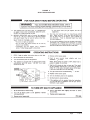
1
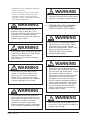
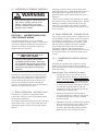
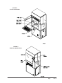
Manual:
Supersedes:
File:
Date:
Bard Manufacturing Company, Inc.
Bryan, Ohio 43506
Since 1914...Moving ahead, just as planned.
2100-502A
2100-502
Vol. I, Tab 20
09-05-08
USER'S INFORMATION MANUAL
WG3S, 4S & 5S - Series Combination Gas/Electric Wall-Mount™
We're pleased you've chosen our air conditioner/gas furnace to supply your cooling/heating needs. Please
keep this manual in a safe, yet readily available place. It contains important and useful information.
ATTENTION, INSTALLER: After installing air conditioner/gas furnace, give the user:
• User's Information Manual
• Installation Instructions
• Parts List
• Warranty Information
ATTENTION, USER! Your installer should give you the above four important documents relating to your
air conditioner/gas furnace. Keep these as long as you do your equipment. Pass these documents on to later
purchasers or furnace users. If any of the four documents are missing or damaged, contact your installer or
manufacturer for replacement. For efficient service, please give your unit model and serial number, from
Section 1 or from your serial rating plate.
WARNING
If the information in this manual is not followed exactly, a fire or explosion
may result causing property damage, personal injury or loss of life.
• Do not store or use gasoline or other flammable vapors and liquids in the vicinity of
this or any other appliance.
• WHAT TO DO IF YOU SMELL GAS
• Do not try to light any appliance.
• Do not touch any electrical switch; do not use any phone in your building.
• Immediately call your gas supplier from a neighbor's phone. Follow the gas
supplier's instructions.
• If you cannot reach your gas supplier, call the fire department.
• Installation and service must be performed by a qualified installer or the gas supplier.
WARNING
Read and follow all safety information in this manual, operating instructions and furnace safety
labels. Failure to follow safety precautions could result in damage, injury or death.
IMPORTANT SAFETY NOTE: You must know how to turn off gas and electricity to air conditioner/gas furnace.
Your qualified installer, service agency or gas supplier can teach you to use controls and switches.
WARNING
Do not use this air conditioner/gas furnace if any part has been under water. Immediately call a
qualified service technician to inspect the unit and to replace any part of the control system
and any gas control which has been underwater.
Thank you for reading these safety statements.
Please read on so you will know how to maintain your air conditioner/gas furnace for years of dependable service.
Manual 2100-502A
Page
1 of 15
CONTENTS
Section 1
Rating Plate Information .............................................. 3
Section 2
Important Safety Precautions ................................ 3 & 4
Section 3
Understanding How Your Furnace and
Air Conditioner Works ........................................... 5 & 6
Section 4
Turning Off Furnace in an Emergency ............... 6, 7 & 9
Figures
Figure 1
Typical Gas Piping ..................................... 8
Figure 2
Step-by-Step Instructions
on Lighting Burners .................................. 11
Figure 3
Filter Locations ....................................... 13
Figure 4
Periodic Inspections ............................... 13
Location of Access Panels
Figure 5
Start Up Procedures ................................ 14
Section 5
Operating Your Furnace ............................................. 10
Section 6
Proper Maintenance of Your Furnace
and Air Conditioner ...................................... 10, 12 & 14
Section 7
Air Conditioning Start Up Procedure
Crankcase Heater ...................................................... 14
Section 8
Ventilation Options ..................................................... 15
Section 9
Replacement Parts .................................................... 15
Section 10
Outdoor Coil .............................................................. 15
Manufactured under the following U.S. Patent Numbers:
5,485,878; 5,022,116; 4,924,934;
4,875,520; 4,825,936
COPYRIGHT DECEMBER 2007
BARD MANUFACTURING COMPANY, INC.
BRYAN, OHIO USA 43506
Manual 2100-502A
Page
2 of 15
SECTION 1 • RATING PLATE INFORMATION
Record the manufacturer’s name, unit model number and serial number below. These are your furnace
rating plate. Record installation date which is important for warranty purposes.
YOUR FURNACE INFORMATION
Furnace Type ________________________________________________________________
Manufacturer’s Name __________________________________________________________
Model Number _______________________________________________________________
Serial Number _______________________________________________________________
Date Installed ________________________________________________________________
Installer/Servicer _____________________________________________________________
Address _____________________________________________________________________
City/State/Zip Code ___________________________________________________________
Telephone Number _____________________________________________________
SECTION 2 • IMPORTANT SAFETY
PRECAUTIONS
2.A HAZARD ALERT SYMBOL
An exclamation point surrounded by a triangle.
2.B SIGNAL WORDS
Years of safe, dependable service are assured
when you understand and follow all safety
precautions.
Signal words “WARNING” and “CAUTION”
alert you to potential hazards.
“WARNING” indicates a potentially hazardous
situation which, if not avoided, could result in
death or serious injury.
“CAUTION” indicates a potentially hazardous
situation which, if not avoided, may result in
minor or moderate injury. It may also be used to
alert against unsafe practices. It can also be used
to signal property damage only potential.
2.C. SAFETY PRECAUTIONS
These are some of our most important safety
precautions; others are throughout this manual.
Please read and follow them.
THIS PRODUCT MUST BE GAS PIPED BY
A LICENSED PLUMBER OR GAS FITTER
IN THE COMMONWEALTH OF
MASSACHUSETTS.
2.1 GAS AND COMBUSTION PRODUCTS
WARNING
Any condition that will allow gas or
combustion products to enter furnace area
can cause nausea, asphyxiation or fire
resulting in damage, injury or death.
Natural gas and propane (LP) gas have
characteristic odors. When your furnace is
operating correctly, you should not smell any
unfamiliar odor. Normally, burning gas with air
produces combustion products which contain
carbon dioxide, oxygen and water vapor. Under
abnormal conditions, combustion products can
contain aldehydes and carbon monoxide.
Manual 2100-502A
Page
3 of 15
• Aldehydes have a strong pungent, acrid smell
that can cause nausea.
• Carbon monoxide is tasteless, colorless and
odorless. It can cause headaches, flu-like
symptoms or nausea. We refer to all these
symptoms as nausea in this manual. It can also
cause death by asphyxiation.
WARNING
Any unfamiliar smell can alert you to
presence of gas or aldehydes. If you
detect any unfamiliar odor follow instruction
in Section 4.B.1. Otherwise, nausea,
asphyxiation or fire could occur resulting in
damage, injury or death.
WARNING
Do not block or cover combustion openings
in the furnace. Blocking or covering these
openings could cause nausea,
asphyxiation or fire resulting in damage,
injury or death.
WARNING
A loud noise may mean faulty burner
ignition. If your furnace makes a loud
noise, turn it off. Follow instructions in
Section 4.B.2. If you don’t turn off your
furnace, it could cause fire or an explosion
resulting in damage, injury or death.
WARNING
Do not operate furnace with blower door
open or removed. Do not alter furnace to
allow operation with blower door removed.
Doing either could allow combustion
products to circulate throughout the
furnace area causing nausea, asphyxiation
or fire resulting in damage, injury or death.
Manual 2100-502A
Page
4 of 15
WARNING
Front door must be in place during furnace
operation. Hot surfaces behind front door.
2.2 STORAGE AND USE OF FLAMMABLE,
CORROSIVE AND COMBUSTIBLE
PRODUCTS NEAR YOUR FURNACE
WARNING
Never store or use flammable liquids or
vapors near or on your furnace. These
include gasoline, kerosene, cigarette
lighter fluid, cleaning fluids, solvents, paint
thinners or painting compounds.
Flammable vapors can travel great
distances before igniting.
WARNING
Never store or use anything near or on
your furnace that can produce vapors that
are corrosive to gas-fired furnaces. Vapors
from products containing chlorines,
fluorines, bromines and iodines can cause
vent system or heat exchanger failure.
Examples of such products are spray or
aerosol containers, detergents, bleaches,
cat litter, waxes, adhesives, solvents and
other cleaning compounds. Vent system
or heat exchanger failure could cause
nausea, asphyxiation or fire resulting in
damage, injury or death.
WARNING
Never store anything combustible near or
on your unit. A fire could occur resulting in
damage, injury or death.
2.3 ALTERATION OF FURNACE CONTROLS
WARNING
Do not alter any gas or electrical controls
(gas control or safety controls) in any
manner. Altering them could cause
furnace to operate unsafely resulting in
damage, injury or death.
SECTION 3 • UNDERSTANDING HOW
YOUR FURNACE WORKS
Your installer should have given you a detailed
explanation of how the furnace operates. Shown below
are the basic operation characteristics and sequence of
operation. If you have any questions consult your
installer and/or service agency.
* * IMPORTANT * *
There are many types of thermostats
compatible with this furnace. Make sure
you understand the specific type installed.
Ask installer for detailed explanation, and
retain thermostat instruction manual for
reference.
The ignition system consists of a direct spark igniter
(DSI) and remote sensor. When the thermostat calls for
heat the DSI sparks to light main burner gas. Once
ignited the remote sensor confirms flame carry over to
all burners.
There is a 60-second delay after main burner is on until
the comfort air blower starts on heating speed. After the
thermostat is satisfied, the burners will go off as gas
valve closes. The inducer will continue to run for 30
seconds, and the comfort air blower will continue to run
for 2-1/2 minutes.
3.2 BASIC OPERATION – COOLING CYCLE
On a call for cool the compressor and condenser fan will
start immediately, and the comfort air blower will start 7
seconds later on cooling speed. Note: Some models
may be equipped with optional Low Ambient Control
that will cycle the condenser fan motor to maintain
proper refrigerant pressures under lower outdoor
temperature conditions. When the thermostat is
satisfied the compressor and condenser fan will stop and
the comfort air blower will continue to operate for 60
seconds.
3.2.1
COMPRESSOR CONTROL MODULE
(CCM)
All models are equipped with a compressor control
module. This control is an anti-short cycle/lockout
timer with high and low pressure switch monitoring and
alarm relay output.
Delay on Make Timer and Break Time Delay
This furnace is equipped with a vent shut-off system
which monitors the combustion air into the burners by
means of a pressure sensing device. When the vent
becomes blocked, this device turns off the gas valve
circuit to prevent flue products from entering the
structure. In the event that this occurs, shut off furnace
and contact a qualified service agency.
3.1 BASIC OPERATION – HEATING CYCLE
This furnace is operated by an Integrated Furnace
Control (IFC) and a gas control system which controls
all functions of the furnace.
On a call for heat from the thermostat, the IFC first turns
on the inducer motor. The pressure switch then closes
signaling the ignition control to proceed with ignition
function.
• On initial power up, or any time the power is
interrupted to the unit, the delay on make period
begins. This delay will be 2 minutes plus 10% of
the delay on break setting. This feature assures
that pressures will be equalized for normal start
up if there are brief power interruptions, and can
accommodate staggered starts for dual unit
installations as long as the off delay periods are
set differently for the two units.
• During routine operation of the unit with no
power interruptions the compressor will operate
on demand with no delay as long as off delay
time has been met.
• Adjustable 30-second to 5-minute delay on break
timer assures that pressures can equalize if units
are short cycled by the operating controls or
personnel. Recommended settings would be 2
minutes for unit 1 and 3 minutes for Unit 2.
Manual 2100-502A
Page
5 of 15
High Pressure Switch and Lockout Sequence
• If the high pressure switch opens, the compressor
contactor will de-energize immediately. The
lockout time in the CCM will go into a soft
lockout and stay locked out until the high
pressure switch closes and the delay on break has
expired.
• If the high pressure switch opens again during
the same operating cycle the CCM will go into a
manual lockout condition.
• Recycling the wall thermostat resets the manual
lockout.
Low Pressure Switch, Bypass and Lockout
Sequence (Optional)
• If the low pressure switch opens for more than
120 seconds the compressor contactor will deenergize and the CCM will go into soft lockout.
• Regardless of the state of the low pressure switch
the compressor contactor will reenergize after
the delay on break time has expired.
• If the low pressure switch remains open, or opens
again for longer than 120 seconds, the CCM will
go into a manual lockout and the alarm relay
circuit will energize.
• Recycling the wall thermostat resets the manual
lockout.
NOTE: Both high and low pressure switch controls
are inherently automatic reset devices. The
high pressure switch opens at 425 and closes
at 325 psig, and the low pressure switch opens
at 14 and closes at 30 psig. The lockout
features, both soft and manual, are a function
of the Compressor Control Module.
Alarm Relay Output
• Alarm terminal on Compressor Control Module
is 24V AC output connection for applications
where signal is desired. This terminal is
powered whenever compressor is in manual
lockout due to high pressure or low pressure
sequences as described.
Manual 2100-502A
Page
6 of 15
PHASE MONITOR
All units with three phase scroll compressors are
equipped with a three phase line monitor to prevent
compressor damage due to phase reversal.
The phase monitor in this unit is equipped with two
LEDs. If the “&” signal is present at the phase monitor
and phases are correct, the green LED will light.
If phases are reversed, the red fault LED will be lit and
compressor operation is inhibited.
3.3 MANUAL FAN (CONTINUOUS AIRFLOW)
OPERATION
If wall thermostat is set to MANUAL (ON) position to
operate comfort air blower continuously to provide air
circulation throughout the building, the blower will
operate at a level that is lower than cooling or heating
airflows. This permits the air to circulate as desired but
helps keep the operating noise level down as well a
conserving energy.
During a call for cooling, the blower automatically
shifts up to cooling speed, and remains there until 60
seconds after thermostat is satisfied then drops back to
heating speed.
SECTION 4 • TURNING OFF FURNACE IN
AN EMERGENCY
WARNING
Have a qualified installer, service agency
or gas supplier teach you location and
operation of gas and electrical shut-off
devices. Ask them any questions you have
about this section. If you don’t turn off your
furnace in an emergency damage, injury or
death could result.
In an emergency you must know how to turn off gas
and electricity. Find out how before the emergency.
WARNING
Should overheating occur or the gas
supply fail to shut off, shut off the manual
gas valve to the furnace before shutting off
the electrical supply. Failure to do so can
cause a fire or explosion which could result
in damage, injury or death.
2. ELECTRICAL SHUT-OFF DEVICES
In an emergency, you may not be able to reach
both of your electrical shut-off devices.
Therefore, you must know how to turn off
electricity using either one of them. Here are
two types of electrical shut-off devices:
a. There should be an electrical shut-off
device located on or immediately adjacent
to the furnace.
b. There should be a separate circuit breaker
or fuse serving only the furnace located in
the main circuit breaker or fuse panel.
Know its location and make sure this device
is clearly identified.
4.A GAS AND ELECTRICAL SHUT-OFF
DEVICES
1. GAS SHUT-OFF DEVICES
In an emergency, you may not be able to reach
all the gas shut-off devices. You must know
how to turn off gas using any one of the three
manual types:
a. Manual Shut-off Switch on Gas Control
Gas control location is behind the access
panel on the right side. See Lighting and
Shutdown Instructions in Section 5 for
more information.
To turn gas control furnace knob OFF, turn
it to “OFF” position. Use this same
procedure when you leave a vacation home
vacant and do not want the furnace to
operate.
b. Manual In-Line Shut-off Valve in Gas
Supply Line.
This valve could be next to furnace.
Figure 1 shows a typical installation.
Normally, gas is ON when you turn the
shut-off valve handle parallel to gas pipe.
Gas is OFF when you turn handle 90° from
gas pipe.
c. Manual Shut-off Valve at Natural Gas
Meter or Propane (LP) Gas Tank.
Normally, natural gas is ON when you turn
shut-off parallel to gas pipe. Gas is OFF
when you turn shut-off 90° from gas pipe.
Some valves require a wrench or other
tools.
Manual 2100-502A
Page
7 of 15
FIGURE 1
TYPICAL GAS PIPING
Manual 2100-502A
Page
8 of 15
4.B POSSIBLE EMERGENCIES AND
RECOMMENDED ACTIONS
WARNING
If gas or electricity is off due to an
emergency, only a qualified installer,
service agency or gas supplier should turn
it back on. Doing it yourself could result in
damage, injury or death.
1. Possible Emergency: Smelling gas or other
unfamiliar smell; or not knowing what may be
wrong or what to do about it.
3. Possible Emergency: Your thermostat is set
above room temperature. The blower is on but
the air coming from your room registers is hot,
then cold, then hot, then cold in a continuing
cycle. This condition indicates lack of airflow
through furnace.
ACTION:
a. Make sure air filter is clean and installed
correctly.
b. Check that registers and return air grilles are
open and unobstructed.
c. If condition continues, call your local
qualified service technician or gas supplier.
ACTION: For your safety –
a. Leave your house or building immediately.
b. Go to a neighbor’s or another building.
4. Possible Emergency: While furnace is operating,
you smell unfamiliar odors that go away when
furnace is off.
c. Use their telephone.
d. Call your gas supplier. Tell them you smell
gas and give them your name and address.
e. If you cannot reach gas supplier, call fire
department.
WARNING
WARNING
Unfamiliar odors may mean gas or
aldehydes are present which could result in
damage, injury or death.
Three important things not to do –
1. Don’t try to light any gas appliances.
2. Don’t touch any electrical switches
3. Don’t use the telephone in your house or
building.
Any of the above may cause a spark, which
could cause a fire or explosion resulting in
damage, personal injury or death.
2. Possible Emergency: Your thermostat is set
below room temperature; yet even though the
blower is on, the air coming from your room
registers continually gets hotter.
ACTION:
ACTION:
a. Turn thermostat to its lowest or OFF setting.
b. Move gas valve control knob to OFF position.
c. If blower is not operating, immediately turn
off electricity to furnace using shut-off
device near furnace or at main circuit panel.
d. If blower is operating, wait five minutes for
furnace to cool down and then turn off
electricity to furnace using shut-off device
near furnace or at main circuit panel.
e. Call your local qualified service technician
or gas supplier.
a. Turn room thermostat to its lowest or OFF
setting.
b. If you can do so safely, turn gas off. Use
manual shut-off valve at gas meter or on
propane (LP) gas tank. You may need a
wrench or tools. If you can safely turn off
electricity at the main circuit panel, do so.
If you cannot do these things safely, leave
your home or building immediately. Call
your gas supplier or fire department from a
neighbor’s phone for help.
Manual 2100-502A
Page
9 of 15
5. Possible Emergency: Main electrical circuit
breaker for furnace cannot be reset without
tripping again or new fuses continue to blow.
ACTION:
a. Move gas valve control knob to OFF.
b. Call your local qualified service technician
or gas supplier.
SECTION 5 • OPERATING YOUR
FURNACE
After reading the Safety Information and Precautions
follow Operating Instructions on front door of furnace
and instructions repeated on Page 11.
WARNING
If you do not follow these instructions
exactly a fire or explosion could occur
resulting in damage, injury or death.
SECTION 6 • PROPER MAINTENANCE
OF YOUR FURNACE
You need special abilities, mechanical skills and tools to
maintain your furnace properly. If you are uncertain
about your abilities or if you lack proper skills or tools,
do not try to maintain or repair your furnace yourself.
Instead, contact a qualified installer, service agency or
gas supplier.
6.A IF YOU SMELL GAS OR ANY UNFAMILIAR
SMELL WHILE WORKING ON YOUR
FURNACE:
1. Do not try to light main burners.
2. Do not touch or turn on any electrical
switch.
3. Do not use any phone in your building.
4. Immediately call your gas supplier from a
neighbor’s phone. Follow gas supplier’s
instructions.
5. If you cannot reach your gas supplier, call
fire department.
6.B LUBRICATION REQUIREMENTS
WARNING
Never use tools to move gas control knob.
Only use your hand. If gas control knob
will not move by hand, do not force it or try
to repair it. Call a qualified installer,
service agency or gas supplier. Forcing
knob can cause gas to leak which could
result in fire or explosion resulting in
damage, injury or death.
Properly operating your furnace requires certain
abilities, mechanical skills and tools. If you are
uncertain about your abilities or if you lack proper skills
or tools, do not proceed. Instead, contact a qualified
installer, service agency or gas supplier.
An automatic ignition device lights the burners. Do not
try to light manually. See Figure 2 on Page 11 for step
by step instructions.
The main blower motor, outdoor fan motor,
and the induced draft blower motor are
permanently lubricated, and no maintenance is
required.
6.C MAKE SURE AIR FILTER(S) IS IN PLACE
Ask your installer, local qualified service
technician or gas supplier to make sure your
filter(s) is in place properly. Become familiar
with its location and procedures for removing,
cleaning and replacing it.
Recommended filter sizes are shown below.
Main System Filter: 20x30x2 throwaway for
WG3S, WG4S & WG5S models.
See Figure 3 on Page 13 for filter locations.
WARNING
Operating furnace without clean air filter(s)
can damage blower motor, heat exchanger
or air conditioning system components.
This can cause system failure which could
result in damage or injury.
Manual 2100-502A
Page
10 of 15
FIGURE 2
START UP PROCEDURE
Manual 2100-502A
Page
11 of 15
6.D KEEP AIR FILTER(S) CLEAN
As a user, your personal responsibility is to
keep air filter(s) clean.
CAUTION
A dirty air filter(s) reduces system
efficiency and can cause erratic control
performance. These could result in
damage to blower motor or heat
exchanger.
1. During the first four weeks after your
furnace is installed, inspect your air filter(s)
for dirt every week. Then check the filters
monthly and replace as necessary.
2. If the filter(s) is of a washable type, clean
filter(s) according to the manufacturer’s
specifications.
WARNING
After cleaning or changing filter(s), filter
access must be closed and latched.
Failure to do so could cause nausea,
asphyxiation, or fire resulting in damage,
injury or death.
6.E DO NOT OBSTRUCT DUCT WORK
For proper operation, keep registers and return
air grilles open. Do not cover or block them
with rugs, carpets, drapes or furniture.
6.F HAVE YOUR FURNACE CHECKED
ANNUALLY
The furnace, vent terminal, and the combustion
air intake hood should be inspected yearly by a
qualified service agency, generally prior to the
heating season. Detailed procedures for this
inspection are contained in the instructions
booklet and should be handled by the qualified
service agency only.
A general inspection of the furnace, the furnace
area and the vent terminal should be conducted
on a regular basis by the owner/occupant. This
review should include:
1. Make sure the furnace always has the
minimum clearance as detailed on the
furnace rating plate. Special attention must
be given to these items if any remodeling is
done.
Manual 2100-502A
Page
12 of 15
2. Make sure the vent terminal is in place and
is physically sound.
3. Reviewing that the return air duct
connection(s) is physically sound, is sealed
to the furnace casing.
4. The physical support of the furnace is
sound without sagging, cracks, gaps, etc.
around the unit so as to provide a seal
between the unit and the structure.
5. Inspect for any obvious signs of
deterioration of the furnace.
6. Periodic examinations of the vent terminal
should also be conducted by the owner on a
regular basis, preferably every month but
at least every two months during the heating
season.
7. Check the entire vent terminal for any
blockage. If any debris is present remove it.
8. If unit is vertically vented, inspect vent
system annually including drain tube.
Clean or replace if necessary.
6.G THE FOLLOWING PROCEDURE SHOULD
BE FOLLOWED FOR THE PERIODIC
INSPECTION AS CONDUCTED BY THE
OWNER/OCCUPANT.
1. Set the wall thermostat to the OFF position
or lower the set point lever to a temperature
well below the existing room temperature.
Shut off electric power to the furnace. A
circuit breaker is located behind the lower,
small access panel on the right side.
2. Remove the burner access door. See
Figure 4.
3. Use flashlight or trouble light to observe the
burner compartment and burners. There
should be very minimal scaling or sooting
in this area. Any loose debris may be
vacuumed out. Also observe the sides of
the heat exchanger tubes for “hot spots” due
to improper burner alignment or overfiring
and give particular attention to any area
where it looks like there may be any
deterioration from corrosion or rusting.
Observe for any corrosion on the burners
themselves. Should anything appear
questionable, contact your service agency.
FIGURE 3
FILTER LOCATIONS
FIGURE 4
PERIODIC INSPECTIONS
Manual 2100-502A
Page
13 of 15
4. Inspect the vent terminal, or vent system
observing for any debris from weather,
birds, and the like. Clean if necessary.
Also check the combustion air inlet hood to
make sure it is clear. See Figure 4.
WARNING
Leakage of products of combustion into the
living area may result in asphyxiation
resulting in injury or death
SECTION 7 • AIR CONDITIONING START
UP PROCEDURE CRANKCASE HEATERS
FOR NON-SCROLL COMPRESSOR UNITS
All models covered by this user guide utilize a
compressor crankcase heater. It is secured on the
exterior of the compressor at its base, and is controlled
internally within the control panel to be energized
anytime the compressor is off.
Some form of crankcase heat is essential to prevent
liquid refrigerant from migrating to the compressor,
causing oil pump out on compressor start-up and
possible valve failure due to compressing a liquid.
The decal in Figure 5 is affixed to all outdoor units with
crankcase heaters detailing start-up procedures. This is
very important. Please read carefully.
5. Restore the electrical power to the furnace
by turning the switch back on. Adjust the
thermostat to call for heating operation.
6. Observe the main burners flames. The main
burners should be mostly “blue” with
possibly a little orange (not yellow) at the
tips of the flames. The flames should be in
the center of the heat exchanger
compartments and not impinging on the
heat exchanger surfaces.
7. Observe the flames until the blower starts
(there is a normal delay 30 second period
until the heat exchanger warms up). There
should be no change in the size or shape of
the flame. If there is any wavering or
blowing of the flame on the blower start-up,
it is an indication of a possible leak in the
heat exchanger. Turn off the gas valve in
the gas line leading to the furnace, and then
the main electrical switch to the furnace and
call your service agency.
8. Replace the burner access door.
FIGURE 5
START-UP PROCEDURES DECAL
IMPORTANT
These procedures must be followed at initial start-up and at any time power has
been removed for 12 hours or longer.
To prevent compressor damage which
may result from the presence of liquid
refrigerant in the compressor crankcase.
1. Make certain the room thermostat is in
the “off” position (the compressor is not to
operate).
2. Apply power by closing the system
disconnect switch. This energizes the
compressor heater which evaporates the
liquid refrigerant in the crankcase.
3. Allow 4 hours or 60 minutes per pound
of refrigerant in the system as noted on
the unit rating plate, whichever is greater.
4. After properly elapsed time, the
thermostat may be set to operate the
compressor.
5. Except as required for safety while
servicing—Do not open system
disconnect switch.
7961-061
Manual 2100-502A
Page
14 of 15
SECTION 8 • VENTILATION OPTION
ASSEMBLIES
The standard Blank Off Plate (BOP) is installed on the
inside of the vent option door to cover the air inlet
openings which eliminates outside air from entering the
unit.
The optional Commercial Room Ventilator (CRV)
allows up to 50% outside fresh air to be introduced to
the building and includes a built-in exhaust damper.
The CRV complies with ASHRAE Standard 62.1
“Ventilation for Acceptable Indoor Air Quality”.
The optional EIFM-Series Economizer allows for nonmechanical cooling when the outdoor temperature and
humidity conditions allow. It has automatic controls
that are set to lock out the mechanical cooling and
draw air from outside to cool the structure when the
outside air is below the control set point. This device
can also allow some continuous fresh air to be drawn
into the structure depending on its minimum position
setting.
SECTION 9 • REPLACEMENT PARTS
Replacement parts for the gas/electric units are available
through local distributors.
A replacement parts list manual is supplied with each
unit. When ordering parts or making inquiries
pertaining to any of the units covered by these
instructions, it is very important to always supply the
complete model number and serial number of the unit.
This is necessary to assure that the correct parts (or an
approved alternate part) are issued to the service agency.
SECTION 10 • OUTDOOR COIL
Periodic cleaning of the outdoor coil to permit full and
unrestricted airflow circulation is essential. Reduced
airflow through the outdoor coil can shorten equipment
service life as well as increase operating costs.
The optional ERV-Series Energy (Heat) Recovery
Ventilator allows for a continuous change of outside
and inside air. It recovers up to 65% of the energy to
minimize the economic impact of conditioning the
space with fresh air when applying ASHRAE Standard
62.1 fresh air requirements.
Manual 2100-502A
Page
15 of 15