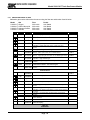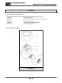
1
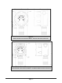
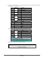
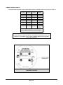
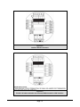
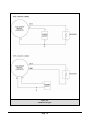
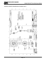
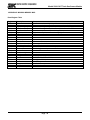
MODEL 5100-XX-IT IT Series TOXIC GAS SENSOR MODULE Version 2.0 APPLICABILITY & EFFECTIVITY Effective for all Model 5100-XX-IT and 5100-XX-IT-SS Modules manufactured after March 1, 2008 including. 5100-03-IT 5100-04-IT 5100-05-IT 5100-06-IT Instruction Manual Part Number T12020 Rev A THIS PAGE INTENTIONALLY LEFT BLANK Contents TABLE OF CONTENTS 1. PRODUCT DESCRIPTION .............................................................................................................................1 1.1 GENERAL........................................................................................................................................................1 1.2 PRODUCT CONFIGURATION........................................................................................................................1 1.3 THEORY OF OPERATION ..............................................................................................................................1 1.4 MODES OF OPERATION................................................................................................................................1 1.4.1 SENTRY INTERFACE..............................................................................................................................1 1.4.2 MODBUS OPERATION............................................................................................................................2 1.4.3 ANALOG OPERATION ............................................................................................................................2 1.4.4 REMOTE SENSOR AND DISPLAY (APPENDIX D)................................................................................2 1.4.5 REMOTE ALARM RESET (DIGITAL INPUT) (Figure 3-7) ......................................................................2 1.4.6 OPTIONAL INTEGRAL RELAYS .............................................................................................................2 MECHANICAL ............................................................................................................................................................2 1.4.7 ENCLOSURE ...........................................................................................................................................2 1.4.8 TRANSMITTER ELECTRONICS .............................................................................................................4 1.4.9 SENSOR ASSEMBLY ..............................................................................................................................4 1.5 INTERCONNECT WIRING ..............................................................................................................................4 1.6 POWER REQUIREMENTS .............................................................................................................................4 2. CAUTIONS & WARNINGS .............................................................................................................................5 2.1 2.2 2.3 INTRODUCTION .............................................................................................................................................5 IT MODULES - GENERAL ...............................................................................................................................5 WIRING............................................................................................................................................................5 3. INSTALLATION ..............................................................................................................................................7 3.1 SENSOR MODULE LOCATIONS....................................................................................................................7 3.2 WIRING............................................................................................................................................................7 3.2.1 ANALOG 4-20 mA OPERATION..............................................................................................................7 3.2.2 MODBUS OPERATION USING RS-485 CONNECTION ........................................................................7 3.2.3 SENTRY OPERATION USING SMC SENTRY CONNECTION ..............................................................7 3.2.4 GENERAL ................................................................................................................................................7 3.3 ENCLOSURE INSTALLATION........................................................................................................................8 3.4 TRANSMITTER AND SENSOR INSTALLATION ............................................................................................8 3.5 MODULE ADDRESS SWITCH ......................................................................................................................10 4. OPERATION .................................................................................................................................................17 4.1 4.2 4.3 4.4 4.5 INTRODUCTION – HUMAN-MACHINE INTERFACE SYSTEM ...................................................................17 HUMAN-MACHINE INTERFACE ..................................................................................................................17 MAIN MENU...................................................................................................................................................18 CONFIGURE SET-POINTS...........................................................................................................................19 MAINTENANCE FUNCTIONS.......................................................................................................................22 5. CALIBRATION ..............................................................................................................................................24 5.1 CALIBRATION FREQUENCY .......................................................................................................................24 5.2 CALIBRATION PREPARATION ....................................................................................................................24 5.2.1 CALIBRATION GAS DELIVERY METHODS .........................................................................................24 5.3 CALIBRATION PROCEDURE.......................................................................................................................24 5.3.1 SENSOR EXPOSURE TO GAS.............................................................................................................25 6. SERVICE .......................................................................................................................................................26 6.1 6.2 6.3 6.4 SENSOR MODULE CONFIGURATION ........................................................................................................26 ENCLOSURE REPLACEMENT ....................................................................................................................26 TRANSMITTER REPLACEMENT .................................................................................................................27 SENSOR REPLACEMENT............................................................................................................................27 Contents 6.5 INSTALLATION INSPECTION ......................................................................................................................27 6.5.2 INSPECTION AND TROUBLESHOOTING GUIDE ...............................................................................28 6.5.3 IF MODULE DOES NOT RESPOND TO GAS ......................................................................................28 6.5.4 IF THE MODULE DISPLAYS “STARTING” FOR MORE THAN 1 HOUR .............................................28 7. APPENDICES ...............................................................................................................................................29 APPENDIX A - SPECIFICATIONS ...........................................................................................................................29 APPENDIX B: - MODEL NUMBERS & PARTS LIST ................................................................................................31 APPENDIX C: LIMITED WARRANTY ......................................................................................................................32 APPENDIX D: REMOTE SENSOR/DISPLAY DRAWING 5394-52 ..........................................................................33 APPENDIX E: MODBUS MEMORY MAP.................................................................................................................34 Contents 1. PRODUCT DESCRIPTION 1.1 GENERAL The Model 5100-XX-IT Toxics Gas Sensor Module is a member of the Information Technology ”IT” family of gas sensor transmitter modules. Members of the IT Toxics family include: • 5100-03-IT Oxygen Deficiency Gas Sensor Module • 5100-04-IT Carbon Monoxide Gas Sensor Module • 5100-05-IT Hydrogen Sulfide Gas Sensor Module • 5100-06-IT Chlorine Gas Sensor Module IT modules offer a broad array of features, including: • Integral alphanumeric LED display • 180 day calibration frequency • 4-20 mA output • Modbus® RTU interface • SMC Sentry interface • 316 Stainless steel enclosure option • Auxiliary integral relay option • Remote display option • Low maintenance and operation costs IT modules are designed, and approved for installation and operation in hazardous locations. 1.2 PRODUCT CONFIGURATION Various module configuration options are available. Where applicable, these options are factory configured prior to shipment. Options which can be re-configured by the installer or field technician are fully described in this manual. 1.3 THEORY OF OPERATION Electrochemical sensors are fuel cell-like devices consisting of an anode, cathode and electrolyte. The components of the cell are selected so a subject gas, allowed to diffuse into the cell, will cause a chemical reaction and generate a current. The cells are diffusion limited so the rate the gas enters the cell is solely dependent on the gas concentration. The current generated is proportional to the rate of consumption of the subject gas in the cell. 1.4 MODES OF OPERATION 1.4.1 SENTRY INTERFACE IT gas sensor modules can be installed on Sierra Monitor Sentry Model 5000 controllers. The gas sensor module communicates as a toxic gas sensor module (Type 4 – communication) and are automatically detected by the Sentry controller. When it is installed in a Sentry system the IT module must have a unique address which can be established by setting an address between 1 and 8 on the Module Address Switch ® Registered trademark of Schneider Electric Page: 1 accessible from the cover plate as illustrated in Figure 3-1. Figure 3-6 in this manual provides the wiring terminations for connections to the Sentry controller. When the module is operated in conjunction with a Sentry controller, the alarms outputs in the module can both be set to “Sentry”, allowing the Sentry controller to manage alarm acknowledge and reset rather than the sensor module. The alarm relay outputs are triggered by the alarm values established in the module, and can be independent of the settings in the Sentry controller. The Sentry configuration allows daisy chain installation using the Sentry multiplex capability, thus reducing costs by avoiding the requirement for wiring junction boxes. The connector card has two sets of connections, allowing for a continuous run to the next module. 1.4.2 MODBUS OPERATION An RS-485 Modbus RTU serial interface allows direct connection to standard PLCs and DCSs. The Module Address Switch (section 3.5) allows the user to select up to 16 different Modbus addresses. Also, an additional 238 Modbus addresses (for a total of 254 different Modbus Addresses) are available via menu selection. Figure 3-6 in this manual provides the wiring terminations for Modbus connections. The 5100-XX-IT provides the additional terminal connectors to enable the user to connect In/Out terminations of a RS-485 connection. 1.4.3 ANALOG OPERATION The 4-20 mA interface allows direct connection to standard analog controllers or PLCs. The 5100-XX-IT 420 mA connection can be wired as a Type 3 (3-wire) or Type 4 (4-wire) circuit as described by ANSI/ISA50.00.01-1975 Standard (see figure 3-5). 1.4.4 REMOTE SENSOR AND DISPLAY (APPENDIX D) The Remote Sensor and Display option (5394-52) can be used to remotely mount the sensor up to 100’ from the transmitter. 1.4.5 REMOTE ALARM RESET (DIGITAL INPUT) (Figure 3-7) An input is available for connection of remote alarm reset/acknowledge. Figure 3-4 provides the wiring termination for connecting the remote alarm reset. This only resets local alarms, not Sentry alarms. This input can be wired as supervised or non-supervised. Note that when the Remote Alarm Reset is operated in a supervised mode that both the switch and resistor must be present as outlined in Figure 3-7. 1.4.6 OPTIONAL INTEGRAL RELAYS The optional relays are integral to the gas sensor module and are rated as SPDT, 250VAC, 8 Amps for the High Alarm and Low Alarm relays and SPDT, 250 VAC, 2 Amp for the Trouble relay. If the gas sensor module is provided with the optional relays, it will include Terminal P4 on the interface board (Figure 3-2). Relay output connections are on P4. MECHANICAL The sensor module of comprised of the following three primary components: 1.4.7 ENCLOSURE Standard on the 5100-XX-IT is an explosion-proof, rain-tight cast aluminum electrical housing (Figure 1-1) with three ¾” FNPT conduit hubs. The 5100-XX-IT-SS (Figure 1-2) has a 316 Stainless Steel enclosure. Both enclosure covers have a viewing window. The design of the enclosure allows 3-way mounting choices as shown in figure 1-3. Page: 2 Figure 1-1 Model 5100-05-IT Toxic Gas Sensor Module – Aluminum Enclosures, Dimensions Figure 1-2 Model 5100-05-IT Toxic Gas Sensor Module – 316 Stainless Steel Enclosures, Dimensions . Page: 3 Figure 1-3 Model 5100-XX-IT Toxic Gas Sensor Module – Mounting Options 1.4.8 TRANSMITTER ELECTRONICS Electronic Assembly consist of one top transmitter board (connected to the cover plate) and on lower interface board. Connectors for wiring for power, signal interface and alarm relays are located on the interface board assembly 1.4.9 SENSOR ASSEMBLY The sensor assembly includes an explosion proof housing containing the gas sensor and a wiring harness for connection to the transmitter. The sensor assembly threads into one hub of the enclosure. The exposed end of the sensor assembly is threaded to allow connection of a rain-shield or calibration gas delivery fitting. 1.5 INTERCONNECT WIRING Not supplied with the sensor module, but necessary to the installation and operation is the multi conductor wiring which connects the module to its power source and controller. Before this wiring is installed it is important to read and understand the control system installation instructions to determine wiring requirements and alternatives. 1.6 POWER REQUIREMENTS IT modules operate on DC power between 10 VDC and 30 VDC. Regulated DC power must be supplied from a separate source, or from an approved Sentry or IT controller. Page: 4 2. CAUTIONS & WARNINGS 2.1 INTRODUCTION Although IT Transmitter Modules are designed and constructed for installation and operation in industrial applications including "hostile" environments, caution should be taken to insure that the installation is made in compliance with this instruction manual and that certain procedures and conditions are avoided. This chapter discusses the necessary cautions. Read the entire chapter prior to installation of the equipment. 2.2 IT MODULES - GENERAL Avoid installing sensor modules where they will be unnecessarily exposed to wind, dust, water (esp. direct hose down), shock, or vibration. Observe temperature range limitations. Sensors may be adversely affected by prolonged exposure to certain materials. Loss of sensitivity, or corrosion, may be gradual if such materials are present in low concentrations. These materials include: Halides (compounds containing chlorine, fluorine, bromine, iodine), acid vapors, caustic liquids or mists. Care has been taken by the manufacturer to ship your modules in protective packaging to avoid contamination prior to installation. It is recommended that the modules remain protected during installation and that the covering be removed immediately prior to system start-up. During normal use the sensor is protected from dirt and oil contamination by a sintered metal cover. If this cover becomes clogged, the response of the sensor will be reduced. Protect the sensor from contamination by careful placement, or by use of rain and dust shields. Sensor modules must not be painted. Paint may contain compounds which will contaminate the sensor. Paint will cause clogging of the sintered metal cover and will cause difficulties during attachment of the calibration head or other maintenance activity. It is recommended that the module be tagged "DO NOT PAINT". 2.3 WIRING The manufacturer recommends that extra caution be taken where the installation is near any sources of electromagnetic or radio frequency interference. Precautions include: • Avoid running sensor module cable close to high power cables, radio transmission lines, or cables subject to pulses of high current. • Avoid running cables near large electric motors or generators. • When the sensor module is to be operated in analog (4-20mA output) mode shielded cable is required. • When the risk of interference is present use shielded cables. In conduit installations the shield should be connected to the conduit. In cable applications the shield should be connected to the cable connector. • All splices must be via either a termination hardware system or soldered. Improperly spliced cable can result in corrosion, resistance changes and system errors. NOTE Installation and wiring must be in accordance with the National Electrical Code. AC Voltage conductors are not to be run in the same conduit as DC voltage conductors. Page: 5 THIS PAGE INTENTIONALLY LEFT BLANK Page: 6 3. INSTALLATION NOTE All IT modules are factory are pre-configured and calibrated. All modules are tagged to indicate the configuration including the sensor module number. Identify all components during unpacking and install using the factory configuration. 3.1 SENSOR MODULE LOCATIONS Select locations for each sensor modules based on the following: • Modules should be placed close to the potential source of gas. • Modules should be placed in areas accessible for calibration. • Sensors should be pointed down and the conduit should include an inverse trap to reduce moisture (condensation) from accumulating in the electronics enclosure. • Remote calibration fitting (5360-00) should be used to facilitate calibration gas delivery. Run polyurethane tubing (1/4” O.D. x 1/8” I.D.) from fitting to an accessible location. 3.2 WIRING 3.2.1 ANALOG 4-20 mA OPERATION The 4-20 mA output for the 5100-XX-IT can be either 3-wire or 4-wire operation. If using 3-wire operation, use a minimum of 18 AWG, shielded, 3-conductor cable up to 2000’. For 4-wire operation, use a minimum of 2 each, 18 AWG, twisted, shielded, pair up to 2000’. 3.2.2 MODBUS OPERATION USING RS-485 CONNECTION Use a minimum of 18 AWG, 2 conductor for DC power connection. No shield required. In addition use a minimum of 24 AWG, low capacitance, shielded data cable for RS-485 half duplex communication. The installation may be planned in a manner which provides up to 32 sensor modules on a single home run. Refer to Figure 3-3 units ship with BIAS jumpers connected. For all installations, except very long cable runs, these jumpers connected. The TERM jumpers should be installed in the last (furthest) module of every loop. 3.2.3 SENTRY OPERATION USING SMC SENTRY CONNECTION Wire shall be rated as 600 volt tray cable, such as Belden (or equivalent) 27331 or 27331 AS (shielded). If high RFI or EMI levels exist wiring should be protected by conduit or shield. The installation may be planned in a manner which provides up to 4 sensor modules on a single home run to a Sentry controller. NOTE: Be sure to follow all local electric code and safety requirements when installing the 5100-XX-IT Gas Sensor Module 3.2.4 GENERAL Install conduit as required by local code or construction specifications. When sensor modules are to be multiplexed for Sentry or RS-485 communication two alternatives may be planned: • Install splice boxes above each sensor module. Use multi-position positive contact terminals to connect daisy chain wiring and provide a pigtail to connect to the sensor module transmitter board. Page: 7 NOTES The drain wire of shielded cable must NOT be used as one of the conductors. Installation and wiring must be in accordance with the National Electrical Code. Temperature o rating of cable wire must be at least 75 C. If cable runs through higher temperature environments, it must be specified for that environment. 3.3 ENCLOSURE INSTALLATION To protect the transmitter and sensor assembly they should be removed from the enclosure and preserved until final installation and wiring termination. Prior to installation and wiring. 1. Remove the transmitter from the module housing by: • Unscrew the two captive panel screws in the face plate. • Lift the transmitter out of the housing. • Unplug the sensor cable from transmitter connector P2. • Remove the sensor assembly from the enclosure hub. 2. Install the module housing onto the end of the supply conduit and/or bolt into position as required. NOTES When housing earth grounding is required for the installation a grounding lug is located in the base of the enclosure. Install the earth ground wire under the green lug. When installing the enclosure be sure to mount the FM Approved plate near the sensor enclosure. This plate states “Caution: this area must be known to be free of flammable concentrations prior to opening the enclosure.” 3.4 TRANSMITTER AND SENSOR INSTALLATION When all pre-wire is complete: 1. Install sensor assembly in the open hub on the module enclosure. The sensor assembly thread must be fully seated into the hub and tightened to maintain explosion proof assembly. 2. Connect the wires which return to the controller to interface board connectors P1, P2, P3 and P4 according to Figure 3-2. 3. Connect the sensor assembly cable to top transmitter board connector P2. 4. Align the headers between the top transmitter board and the lower interface board and push together. 5. Turn rotary switch to correct sensor address. NOTE The interface board should be wired to remote controllers first before installing the front transmitter board. Page: 8 6. Carefully return the transmitter to the enclosure installing it over the two stand-off’s. Tighten the retaining screws into the stand-offs. P1 1 2 3 4 5 6 7 PCB Label Switch IN + IN 4-20 IN + IN GND 4-20 OUT + OUT - Function Digital Input SW + Digital Input SW 4-20 mA Input + 4-20 mA Input Ground 4-20 mA Output + 4-20 mA Output - P2 1 2 3 4 5 6 PCB Label Function RS 485 (+) (A) RS 485 (-) (B) RS 485 shield (Isolated GND) RS 485 (+) (A) RS 485 (-) (B) RS 485 shield (Isolated GND) P3B 1 2 3 P3A 4 5 6 PCB Label P S G Function Power Signal Ground P S G Power Signal Ground RS 485 RS 485 + S + S P4 Connections are only available when the optional Relays are included P4 PCB Label Function 1 N/C Low Alarm Relay NC LO ALM 2 COM Low Alarm Relay COM 3 N/O Low Alarm Relay NO 4 N/C High Alarm Relay NC HI ALM 5 COM High Alarm Relay COM 6 N/O High Alarm Relay NO 7 N/C Trouble Alarm Relay NC * TRBL 8 COM Trouble Alarm Relay COM* ALM 9 N/O Trouble Alarm Relay NO* * Trouble relay is fail safe so it is energized for normal operation, functions are labeled for normal operation. Table 3-1 Sensor Module External Interfaces (See Figure 3-2) 7. Establish the module address according to section 3.5. NOTE The starting delay period normally takes approximately 3 minutes but under some circumstances can take longer. Page: 9 3.5 MODULE ADDRESS SWITCH For digital interface applications the module address switch (or Modbus node) must be set per Table 3-2: POSITION ADDRESS POSITION ADDRESS 1 Sensor 1 9 Sensor 09 2 Sensor 2 A Sensor 10 3 Sensor 3 B Sensor 11 4 Sensor 4 C Sensor 12 5 Sensor 5 D Sensor 13 6 Sensor 6 E Sensor 14 7 Sensor 7 F Sensor 15 8 Sensor 8 0 Software Menu Table 3-2 Sensor Module Address Switch Positions NOTE For Sentry applications only sensor addresses 1-8 are allowed. If using Modbus output sensor addresses 1-15 are available. Position 0 allows the Modbus Address to be set by software menu, in the range 16-254. Figure 3-1 Transmitter Face Plate Page: 10 Figure 3-2 Interface Board Connectors Figure 3-3 RS-485: 120 ohm termination not selected, BIAS shunted for 100K ohm bias Page: 11 Figure 3-4 4-20mA Circuit Types Page: 12 Figure 3-5 4-20mA Circuit Type Connections for 5100-XX-IT Page: 13 For end of line, refer to Figure 3-3 Figure 3-6 Wiring Connections for Modbus and Sentry Interface Page: 14 - OUT + SWITCH IN+ - IN - + + IN SWITCH 4-20 GND 4-20 P1 4.7K OHM (CUSTOMER SUPPLIED) SWITCH IN - 5100-05-IT REMOTE ALARM RESET (SUPERVISED) Figure 3-7 Wiring Connections for Remote Alarm Reset Page: 15 THIS PAGE INTENTIONALLY LEFT BLANK Page: 16 4. OPERATION 4.1 INTRODUCTION – HUMAN-MACHINE INTERFACE SYSTEM The Gas Sensor Module utilizes a visual menu system operated by means of a magnet. A magnetic tool (5358-50) is supplied for this purpose. The menu system is used to configure alarm set-points, calibrate the sensor module, and for maintenance procedures and alarms acknowledge. 4.2 HUMAN-MACHINE INTERFACE The module menu system is operated by means of directing the magnet stick toward each of four independent hall-effect magnetic switches. Each switch functions as if it is a manually activated panel key. The keys are located above and below the faceplate display and are labeled M , E , ▲ and ▼as shown in Figure 4-1. The key functions are as follows: • Key M : MODE • Key E : ENTER • Key ▲: UP (+) • Key ▼: DOWN (-) Key M Key E Key /\ Key \/ Figure 4-1: IT Module – Menu Switch Locations Page: 17 4.3 MAIN MENU Table 4-1 describes the primary man-machine interface operation. Key Function M S M S M S M S E T E T E T E T Display Description Mode Switch [M] Enter Switch [E] Up Switch [▲] Previous Menu Down Switch [▼] Next Menu 5100-XX First screen at power up: Model No. VXX-XX-- Second screen at power up: Version No. STARTING Third screen at start up: Starting Delay XXXPPM M E S T Mode Reference Normal condition - default display ALMRSET: Mode Function - Alarm Reset Banner: "Press [E] to reset alarm" M E S T RESET Alarm Reset XXXPPM M S M S M S M S M S M S E T E T E T E T E T E T Default Display Mode ALMRSET: Mode Function - Alarm Reset Mode CALIB:-- Mode Function - Calibrate Table 5-1 Mode SETUP:-- Mode Function - Set Point Adjustments Table 4-3 Mode MAINT:-- Mode Function - Maintenance Table 4-4 Mode EXIT-?-- Exit Menu Enter XXXPPM Apply Selected Mode (Exit) XXXPPM Default Display (Once a minute the sensor displays module address) Table 4-1 Master Menu Table 4-2 describes the operational display values of the human-machine interface system. DISPLAY STARTING XXX PPM LXXXPPM HXXXPPM CXXXPPM DESCRIPTION Delay from loss of power at start-up Concentration Low Alarm High Alarm Measures gas, concentration exceeds 100% to Full Scale Calibration Mode Acknowledged Function Table 4-2 Operation Display Values Page: 18 Model 5100-XX-IT Toxic Gas Sensor Module 4.4 CONFIGURE SET-POINTS The sensor module set-points menu is used to initially set-up the alarm set points, relay actions, gas type and range, 4-20 mA action and RS-485/Sentry address and baud rates. • Alarm Set-points: Once the Set-up menu is selected, press [E] to activate the Alarm Set-point screen. Use the [▲] or [▼] keys to select Low Alarm or High Alarm menu. Key [▲] will adjust the setpoint upwards and Key [▼] will adjust the value downwards. Once it reaches the desired setpoint, Key [E] will accept it and ACK will appear. Set-points can be configured using this menu up to the following values: 5100-03-IT 5100-04-IT 5100-05-IT 5100-06-IT O2 C0 H2S Cl2 19.5% 500 PPM 20 PPM 5 PPM • Alarm Relay Set-up: Once the Set-up menu is selected, press key [▼] once and press [E] to activate the Relay Set-up menu. Use the [▲] or [▼] keys to select High Alarm or Low Alarm relay menu and press [E]. Use the [▲] or [▼] keys to select the correct alarm relay action for the application, Latch, Sentry or Non-Latch. Selecting “Sentry” enables the Sentry controller to make all alarm action decisions. * indicates the current selection. • Range: Once the Set-up menu is selected, press key [▼] twice and press [E] to activate the Range Set-up menu. Use the [▲] or [▼] keys to select Range menu and press [E]. When “Range” is selected menu provides any choices of ranges available for the gas type selected. Use the [▲] or [▼] keys to select the desired range. If the “User” range is selected, use the [▲] or [▼] keys to adjust the high end of the range desired. • 4-20mA: Once the Set-up menu is selected, press key [▼] three times and press [E] to activate the 4-20mA Set-up menu. Use the [▲] or [▼] keys to select Calib or CalibOut menu and press [E]. The “Calib” section of the menu allows the user to calibrate the 4 mA and 20 mA outputs. To calibrate the 4 mA and 20 mA outputs it is necessary to have an amp meter connected to the 5100XX-IT and upon selecting the 4 mA output calibration then the [▲] or [▼] keys can be used to adjust the 4 mA reading on the amp meter until it reads 4 mA. Similar steps can then be performed for the 20 mA output. The CalibOut section allows the user to select the 4-20 mA output action desired during calibration. * indicates the current selected value. Available selections include: • Track – the 4-20mA value tracks the calibration gas exposed to the gas sensor module Zero – the 4-20mA value is held at 0mA during calibration C1.50mA – the 4-20mA value is held at 1.50mA during calibration C4.00mA – the 4-20mA value is held at 4.0mA during calibration. RS-485 - Once the Set-up menu is selected, press key [▼] four times and press [E] to activate the RS-485/Sentry Set-up menu. Use the [▲] or [▼] keys to select Address or Baud rate menu and press [E]. Note that the 5100-XX-IT has a rotary switch on the faceplate and it is used to select addresses 1-15. When connected to Sentry the user can select 1-8 and using Modbus RS-485 the user can select addresses 1-15. For Modbus addresses above 15, set the rotary switch to 0 and then use the “Address” menu to select any address between 16 and 254. The Baud rate menu allows the user to select a baud rate of 38400, 19200, 9600, 4800 or 2400. * indicates current selection. Page: 19 Model 5100-XX-IT Toxic Gas Sensor Module Key Function Display --0%LEL- M S M S M S M S M S M S M S M S E T E T E T E T E T E T E T E T Description Reference Default Display Mode ALMRSET: Mode Function - Alarm Reset Mode CALIB:-- Mode SETUP:--- Enter Alarms S.P. Function - Alarm Adjust * A Below Down Relays S.P. Function - Relays Adjust * B Below Down Gas S.P. Function - Range Adjust * Page 21 Down 4-20mA S.P. Function - 4-20 mA Adjust * Page 21 Down RS-485 S.P. Function - RS-485/Sentry Output Adjust * Page 21 Mode Function - Calibrate Mode Function - Set Point Adjustments High Alarm Set Point Adjustment Example M S M S E T E T M S M S E T E T Enter H.Alarm S.P. Function - High Alarm Adjust Enter HASP:60- High Alarm Set Point: current = 60 *A Use S or T keys to adjust to new set point Down (x5) HASP:55Enter ACK H.Alarm High Alarm Set Point: new = 55 Momentary Acknowledge of new Set Point S.P. Function - High Alarm Adjust Relays Set Point Adjustment Example M S M S M E T E T E S T M S M S E T E T Enter H. Relay S.P. Function - High Alarm Relay Adjust Down L.Relay S.P. Function - Low Alarm Relay Adjust Enter Latch Down Sentry Down *Sentry Use S or T keys to adjust to new relay action (Latch, Sentry, NonLatc) * indicates current NOTE: Sentry indicates that Sentry controls relay action and not the IT Sensor Module High Alarm Relay set to Sentry Table 4-3A Set-Up Configuration Page: 20 *B Model 5100-XX-IT Toxic Gas Sensor Module Gas Range Adjustment Example M E S T M E S T M S M S M E T E T E S T Enter Range Enter *100 PPM Down 10 PPM Down USER Enter 100 PPM S.P. Function - Range Adjust *C Select [E] to select or S or T to select another and press [E] Press [E] if selecting 0-10 PPM range Press [E] if selecting User adjustable range Select [E] to select or S or T to select another and press [E] 4-20 mA Adjustment Example M S M S M S M S M S M S M S E T E T E T E T E T E T E T Enter Calib S.P. Function - Calib Adjust Enter Out: 4mA Enter 4mA Selects 4 mA Enter ACK Momentary Acknowledge of new Set Point Mode Calib S.P. Function - Calib Adjust Down CalibOut Enter Track *D Use S or T keys to select 4 mA or 20mA S.P. Function - Output during Calibration Adjust Use S or T keys to select Track, Zero, C1.50mA, C4.00mA Track = Output during calibration tracks the calibration gas, Zero = Output is Zero during calibration, C1.50mA = Output during calibration is 1.50 mA, C4.00mA = Output during calibration is 4.0 mA M E S T Enter *Track * = Current selection RS-485 Adjustment Example M E S T M E S T M S M S M S M E T E T E T E S T Enter Address S.P. Function - RS-485 Address Adjust Enter Addr:016 Use S or T keys to enter new address Enter ACK Enter Address Down Baud Enter *38400 New address selected S.P. Function - RS-485 Address Adjust S.P. Function - RS-485 Baud Rate Adjust Press [E] to select or [S] or [T] to select another Table 4-3B Set-Up Configuration Page: 21 *E Model 5100-XX-IT Toxic Gas Sensor Module 4.5 MAINTENANCE FUNCTIONS The maintenance menu enables the operator to view sensor and software versions. Sierra Monitor technical support has access to other values as needed.. The maintenance menu operation is described in Table 4-4. Key Function Display XXXPPM M S M S M S M S M S M S E T E T E T E T E T E T Description Default Display Mode ALMRSET: Mode Function - Alarm Reset Mode CALIB:-- Mode Function - Calibrate Mode SETUP:- Mode Function - Set Point Adjustments Mode MAINT:-- Mode Function - Maintenance Enter Ver1.00aA Enter CCC001 Module Software Version Number Module Custom Configuration Control number Table 4-4 Maintenance Menu Page: 22 Reference Model 5100-XX-IT Toxic Gas Sensor Module THIS PAGE INTENTIONALLY LEFT BLANK Page: 23 Model 5100-XX-IT Toxic Gas Sensor Module 5. CALIBRATION 5.1 CALIBRATION FREQUENCY The 5100-XX-IT has been calibrated in the factory prior to shipment. It is recommended that the user check calibration before placing in service. The toxic sensor module must be calibrated every six months. Periodic functional tests are advisable for critical applications and hostile environments. The sensor module microprocessor software includes high level self checking algorithms which provide continuous sensor diagnostic and self adjustment. Users may elect to increase calibration periods based on low drift experience during the first two calibration periods. 5.2 CALIBRATION PREPARATION Calibration of the Toxic Gas Sensor Module is accomplished by simple menu based steps and application of span gas. NOTE If an error is made during any stage of the calibration process, hold the magnet stick at the Switch [M] for 10 seconds. A scrolling display will indicate “Calibration aborted” and the sensor module will exit the calibration activity and return to normal operating mode. The calibration procedure can then be restarted Calibration must be performed only when the area is known to be clear of the applicable toxic gas. necessary, use a portable instrument to confirm that there is no background toxic gas. If For compliance with Factory Mutual (FM) Apparatus, the Sierra Monitor Model 1250-01, 1256-01, 1260-XX are the only FM Approved calibration gas delivery device. Use Model 5358-00 or 5358-01 Calibration Adapter or Model 5360-00 Gas Delivery Fitting. 5.2.1 CALIBRATION GAS DELIVERY METHODS Calibration gas is can be delivered to the sensors via the following delivery devices: Model 5358-00: Calibration Adapter - used with portable calibrators. See 5-1. Model 5360-00: Calibration Gas Delivery fitting - permanently installed fitting which allows tubing to be run to a convenient delivery location 5.3 CALIBRATION PROCEDURE Table 5-1 shows the step by step process of the calibration procedure. The procedures requires that the menu “keys” be activated using the magnet stick. Each key press steps through the process of setting the zero value for clean air and then setting the span value. At each of these steps, apply calibration gas of the value corresponding to the setting accepted on the sensor module display. Page: 24 Sample Gas In Figure 5-1 Model 5358-01 Calibration Adapter Model 5100-XX-IT Toxic Gas Sensor Module 5.3.1 SENSOR EXPOSURE TO GAS Calibration gas must be delivered to the sensor using the flow rate and duration listed in below: Model 5100-03-IT 5100-04-IT 5100-05-IT 5100-06-IT Gas Oxygen Carbon Monoxide Hydrogen Sulfide Chlorine Key Function E T E T E T M E S T Mode ALMRSET: Mode CALIB:-- Enter Reference Default Display Mode Function - Alarm Reset Mode Function - Calibrate Operation: Confirm area clear of gas, or apply zero air to sensor. Enter ACK Enter Enter Zero gas setting acknowledged Banner: Select span, enter <E> to calibrate sensor Sub A C 4 PPM Banner: Apply span gas, then enter <E> to calibrate gas sensor Sub B C 4 PPM Operation: Apply calbration gas. CXXXPPM M E S T Description CAL-0PPM-- Banner: Apply zero gas, enter <E> when done 10PPM-SP M E S T Period Until Stable Until Stable Until Stable Until Stable Display XXXPPM M S M S M S Flow 300 cc/min 300 cc/min 300 cc/min 300 cc/min CAL-OK WAIT-300 Operation: As gas is applied the reading will increase - wait 3 minutes Calibration Passed - now remove gas Operation: Five minute time out before sensor is returned to service. Sub-Routines M S M S M S M S E T E T E T E T M E S T 10PPM-SP Banner: Select span, enter <E> when done Up 25PPM-SP Operation: Change Span Gas Value to 25PPM Up Adj-SPAN Operation: User adjustable value Enter 25PPM-SP Operation: Ready for user adjustment Enter C 25PPM Banner: Apply 25PPM gas, then enter <E> to calibrate gas sensor C 25PPM Operation: Apply calbration gas. CAL-FAIL Operation: No calibration gas applied, or sensor did not respond correctly. Operation: Five minute time out before sensor is returned to service. Operation: Hold magnet over Mode Switch for ten senconds to abort calibration Enter WAIT-300 M E S T Mode (Any) Banner: Calibration Aborted XXXPPM Default Display Table 5-1 Calibration Page: 25 Sub A Sub B Sub C Model 5100-XX-IT Toxic Gas Sensor Module 6. SERVICE 6.1 SENSOR MODULE CONFIGURATION The gas sensor module is comprised of the following sub-assemblies (Figure 6-1): 5100-XX-IT Gas Sensor Module SPL21810 Aluminum Enclosure (SPL32178 316SS Enclosure) SPL21825 Transmitter Assembly XXXXXXX Sensor Assembly (See Appendix B) 5200-XX-IT Sensor (See Appendix B) 6.2 ENCLOSURE REPLACEMENT Figure 6-1 Module Components Page: 26 Model 5100-XX-IT Toxic Gas Sensor Module The enclosure should be replaced if the cover threads or conduit threads have been damaged, or if the enclosure has been damaged sufficiently that it no longer meets the required NEMA classification. To replace the enclosure follow the transmitter and sensor assembly removal instructions, remove the damaged enclosure from its conduit, install a new enclosure and replace the transmitter and sensor assembly. 6.3 TRANSMITTER REPLACEMENT The transmitter assembly should be replaced when it is determined that it is unreliable, noisy or cannot be adjusted for calibration. This may occur due to age, corrosion or failed components. To replace the transmitter assembly: a. Remove the cover of the main enclosure b. Unscrew the two thumb screws in the top of the cover plate, lift the assembly and rotate 90o to relieve the wiring service loop c. Unplug the sensor connector from the transmitter d. Plug connector into new transmitter (be sure to match numbers between connector and socket). e. Restore power and allow a minimum of 3 hours for stabilization before re-calibration 6.4 SENSOR REPLACEMENT The gas sensor which is located inside the sensor assembly housing can be replaced without replacement of the housing. The gas sensor needs replacement when: The “CAL-FAIL” message appears after calibration The sensor output signal is noisy, causing erroneous gas level readings To replace the sensor: a. Confirm that system power has been removed b. Remove the gas sensor module enclosure cover, c. Unscrew the two thumb screws in the top of the faceplate, lift the transmitter assembly and rotate 90o to relieve the wiring service loop. d. Unplug the sensor connector from the transmitter e. Unscrew the old sensor assembly from the enclosure conduit hub. Remove the sensor assembly with its harness f. Unscrew sensor housing cover from the sensor (be sure to loosen the set screw first) g. Carefully pull the old sensor straight up from the socket h. Press the new sensor into the socket. i. Reverse the preceding steps to install the sensor assembly. j. Allow the new sensor to stabilize for a minimum of 3 hours and then calibrate using the procedure in Section 6. 6.5 INSTALLATION INSPECTION Prior to system start-up or trouble shooting the entire system should be visually inspected. The following are guidelines for that inspection: 6.5.1.1 CONTROLLER INSTALLATION • Controller installed in conformance to instruction manual recommendations. • AC power is correctly grounded. • Hot AC and relay connections have safety covers installed. Page: 27 Model 5100-XX-IT Toxic Gas Sensor Module 6.5.1.2 SENSOR MODULE INSTALLATION • Module installation in conformance with this manual. • Modules accessible for calibration. • Wiring terminations clean and correct. 6.5.1.3 MOISTURE TRAPS AND RAINSHIELDS • Conduit seals and drains installed to avoid moisture build up in electronics enclosure. Water accumulation in sensor module enclosures is a major cause of damage and system failures - take precautions to seal electrical conduits and provide moisture traps and drains to avoid water damage • Rain-shields installed where applicable. 6.5.1.4 STANDARD VOLTAGES • DC Voltage to be applied to the sensor module must be between 10 VDC and 30 VDC. 6.5.2 INSPECTION AND TROUBLESHOOTING GUIDE The inspection and troubleshooting guide can be used to step through the system start-up and to determine the corrective action if a fault occurs. 6.5.3 IF MODULE DOES NOT RESPOND TO GAS 1. 2. 3. 4. Repeat calibration procedure. Remove the gas and wait for the timer to completely count down. Apply 50 PPM and verify that the sensor sees 50 PPM gas after calibration. If the sensor still does not see gas, power cycle the unit and repeat calibration. 6.5.4 IF THE MODULE DISPLAYS “STARTING” FOR MORE THAN 1 HOUR 1. Make sure the sensor is placed in an ambient room temperature environment. 2. Power cycle the sensor. 3. Ensure that the sensor is not exposed to the gas of interest during warm-up. 6.5.4.1 IF THE MODULE DOES NOT DISPLAY THE CORRECT PPM 1. Power cycle the unit 2. Recalibrate the sensor. 6.5.4.2 IF THE DISPLAY SHOWS ‘F’ 1. 2. 3. 4. Power down the unit Open the enclosure and unplug the sensor assembly from the transmitter board. Plug the sensor back into the transmitter board carefully and ensure a secure fit. Power up the unit. 6.5.4.3 IF THE DISPLAY SHOWS ‘C’ 1. Complete calibration and exit to operating mode. 6.5.4.4 IF THE DISPLAY SHOWS ‘S’ 1. Check connections with Sentry Connections. Page: 28 Model 5100-XX-IT Toxic Gas Sensor Module 7. APPENDICES APPENDIX A - SPECIFICATIONS Sensor type: Max. Range User Settings Range Zero Drift Repeatability Linearity Resolution Response Time (1) Accuracy Sensor Life 5100-03-IT O2 0-25 %Vol +/- 0.1% +/- 0.2% +/- 0.2% +/- 0.1% <10 sec +/- 0.2% 2 years Electrochemical 5100-04-IT CO 0-1000 PPM 0-100, 0-500, variable +/- 1 PPM +/- 1 PPM +/- 1 PPM 0.5 PPM <25 sec. +/- 1 PPM 2 years 5100-05-IT H2S 0-100 PPM 0-10, variable +/- 0.5 PPM +/- 1 PPM +/- 1 PPM 0.1 PPM <30 sec. +/- 0.5 PPM 2 years 5100-06-IT Cl2 0-10 PPM 0-5, variable +/- 0.5 PPM +/- 0.5 PPM +/- 0.5 PPM 0.1 PPM <60 sec +/- 0.5 PPM 2 years (1) Response time to 90% full signal value for applied concentration (2) Sensor life typical for use at standard temperature and pressure with occasional exposure to gas of interest Output: Display: Relays (Optional): Analog Output (Optional) Signal Output: Fixed and Scrolling LED 8 Amp, High Alarm, Low Alarm, 2 Amp Trouble all SPDT Analog 4-20 mA (Trouble 0 mA, Calibration 1.5 mA) Sentry bus Serial RS-485 Modbus RTU Remote Alarm Reset: Normally open digital input (supervised or non-supervised) Power consumption: Connection type: Input voltage: 2 watts 3 wire 24 VDC nominal: 10-30VDC Input: Electrical Data: Operating Range: Ambient Temp (oF) Ambient Temp (oC) Relative Humidity 5100-03-IT O2 5 to 122 oF -15 to 50 oC 5 – 99% 5100-04-IT CO -4 to 122 oF -20 to 50 oC 5 – 99% 5100-05-IT H2S -40 to 122 oF -40 to 50 oC 5 – 99% 5100-06-IT Cl2 -4 to 122 oF -20 to 50 oC 5 – 99% Enclosure: Material - Standard: Material - Stainless Steel Option Dimensions: (H x W x D) Weight: Housing: Electrical Classification Performance: Approvals: FM Approved Polyester powder-coated, sand-cast, copper-free aluminum 316 Stainless Steel (FM approval pending) 7.5 x 5.0 x 4.8 inches Al, 7.5 x 5.0 x 4.4 inches SS (21.6 x 12.7 x 12.2 cm) 2.7 lb. (1.3 Kg) (standard Aluminum enclosure) 5.4 lb. (2.6 Kg) 316 Stainless Steel NEMA 4X Explosion proof, Class 1, Div. I, Groups B, C, D Class I, Zone 1, groups IIB+H2 IP66 Performance and Safety Approval Pending Page: 29 Model 5100-XX-IT Toxic Gas Sensor Module Modbus: Warranty: Baud: Parity: Stop bit: Data bits: 38400 (Adjustable 2400 to 38400 Baud) None 1 8 Flow Control: Memory map: None Appendix E Limited Warranty 2 years Specifications subject to change without notice Ordering Information: 5100 XX |- 5100 Series | |- 03 = O2 |- 04 = CO |- 05 = H2S |- 06 = Cl2 IT | | |- IT Series YY | | | |- Al (Aluminum Enclosure) |- SS (Stainless Steel) ZZ | | | |- 01= Sentry, RS-485, 4-20mA, & Digital Input |- 02= Sentry, RS-485, 4-20mA, Digital Input & Relays Page: 30 Model 5100-XX-IT Toxic Gas Sensor Module APPENDIX B: - MODEL NUMBERS & PARTS LIST Sensor Module 5100-03-IT 5100-03-IT-SS 5100-04-IT 5100-04-IT-SS 5100-05-IT 5100-05-IT-SS 5100-06-IT 5100-06-IT-SS Gas Sensor Module, Oxygen Gas Sensor Module, Oxygen, Stainless Steel Enclosure Gas Sensor Module, Carbon Monoxide Gas Sensor Module, Carbon Monoxide, Stainless Steel Enclosure Gas Sensor Module, Hydrogen Sulfide Gas Sensor Module, Hydrogen Sulfide, Stainless Steel Enclosure Gas Sensor Module, Chlorine Gas Sensor Module, Chlorine, Stainless Steel Enclosure Options 5394-52 5311-00 Remote Sensor/Display Option Rainshield Calibration Items 1250-01 1250-03 1260-00 1260-04 1260-05 1260-06 1260-13 5360-00 1256-01 1265-03 5358-01 5358-50 Gas Sensor Calibration Kit, Type A (O2, CO, H2S) Gas Sensor Calibration Kit, Type C (Cl2) Gas Cylinder, Air, (Type A) , 105 litres Gas Cylinder, CO 100 PPM, (Type A) 57 litres Gas Cylinder, H2S in N2, 25 PPM, (Type A) 57 litres Gas Cylinder, Cl2, 5 PPM, (Type C) 104 litres Gas Cylinder, CO, 1000 PPM, (Type A), 105 liters Calibrator Head Standard Regulator Type A Calibrator Regulator Type C Calibrator Calibration Adapter - Direct, Standard Calibration/Configuration Magnetic Tool 5200-03-IT 5200-04-IT 5200-05-IT 5200-06-IT SPL21834 SPL21832 SPL21830 SPL21833 SPM27082 SPM27083 SPM27079 SPM27084 SPL21824 SPL21810 SPL21825 SPL21825 SPL27826 Sensor, for 5100-03-IT Sensor, for 5100-04-IT Sensor, for 5100-05-IT Sensor, for 5100-06-IT Sensor Assembly, Aluminum, for 5100-03-IT Sensor Assembly, Aluminum, for 5100-04-IT Sensor Assembly, Aluminum, for 5100-05-IT Sensor Assembly, Aluminum, for 5100-06-IT Sensor Assembly, 316SS, for 5100-03-IT Sensor Assembly, 316SS, for 5100-04-IT Sensor Assembly, 316SS, for 5100-05-IT Sensor Assembly, 316SS, for 5100-06-IT Transmitter Enclosure, Transmitter, Aluminum Enclosure Transmitter, 316SS Interface Board with Relay Interface Board without Relay Spare Parts Page: 31 Model 5100-XX-IT Toxic Gas Sensor Module APPENDIX C: LIMITED WARRANTY SIERRA MONITOR CORPORATION warrants its products to be free from defects in workmanship or material under normal use and service for two years after date of shipment. SMC will repair or replace without charge any equipment found to be defective during the warranty period. Final determination of the nature and responsibility for defective or damaged equipment will be made by SMC personnel. All warranties hereunder are contingent upon proper use in the application for which the product was intended and do not cover products which have been modified or repaired without SMC approval or which have been subjected to accident, improper maintenance, installation or application, or on which original identification marks have been removed or altered. This Limited Warranty also will not apply to interconnecting cables or wires, consumables (ie. calibration gases, batteries, sensors), nor to any damage resulting from battery leakage. In all cases SMC’s responsibility and liability under this warranty shall be limited to the cost of the equipment. The purchaser must obtain shipping instructions for the prepaid return of any item under this warranty provision and compliance with such instruction shall be a condition of this warranty. Except for the express warranty stated above, SMC disclaims all warranties with regard to the products sold hereunder including all implied warranties of merchantability and fitness and the express warranties stated herein are in lieu of all obligations or liabilities on the part of SMC for damages including, but not limited to, consequential damages arising out of/or in connection with the use or performance of the product. Page: 32 Model 5100-XX-IT Toxic Gas Sensor Module APPENDIX D: REMOTE SENSOR/DISPLAY DRAWING 5394-52 Page: 33 Model 5100-XX-IT Toxic Gas Sensor Module APPENDIX E: MODBUS MEMORY MAP Read Register Table Register 40001 40002 40003 40004 40005 40006 40007 40008 40009 40010 40011 40012 40013 40014 40015 40016 40017 40018 40019 40020 40021 40022 40023 40024 40025 Description Concentration Temperature High Alarm Relay Low Alarm Relay Low Alarm Value High Alarm Value Reserved Reserved Reserved Reserved Trouble Bits Trouble High Alarm Immediate Low Alarm Immediate Random ID Restart Count Run time – high Run time – low Max. gas value Model Range Units Temperature Units Gas Scale Temperature Scale Comments Gas Concentration multiplied by 100 Temperature in degrees Celsius scalled by a factor of 100 Boolean indicating the High Alarm Status, 0 No Alarm, 1 High Alarm Boolean indicating the Low Alarm Status, 0 No Alarm, 1 Low Alarm Low alarm set point, used for activating Alarms High alarm set point, used for activating High Alarms 0 for no trouble 1 for any trouble, 0 for no trouble Like 40003. but never latched Like 40004, but never latched Randomly generated permanent ID of sensor In minutes In minutes *scale ((see 40024) 51005, 51003, 51004, 51006, etc *scale (see 40024) 3 is PPM 0 is C, 1 is F Value like 1 or 100 Value like 1 or 100 Page: 34