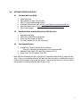
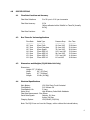
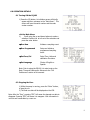
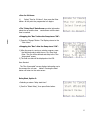
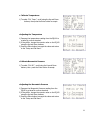
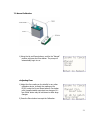
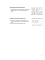
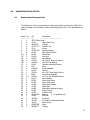
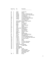
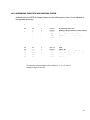
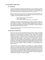
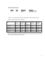
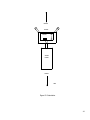
1
PQ100 (Firmware Version 6.0 or 1.0M and higher) Air Sampler INSTRUCTION MANUAL PM10 REFERENCE SAMPLER DESIGNATION NO. RFPS-1298-124 BGI Incorporated 58 Guinan Street Waltham, MA. 02154 Tel: 781.891.9380 Fax: 781.891.8151 e-mail: [email protected] www.bgiusa.com Manual Version: 7.1.1 April, 2013 PREFACE There are now two separate manuals governing the set up, operation and maintenance of the PQ100 Air Sampler. There have been detail improvements in the electronic and firmware functionality such that the addition of further appendices would render a single manual unwieldy. Since Version 1.0M of the PQ 100 adds an improved button and screen layout as well as a choice of Standard (Mass) or Volumetric flow rate, the time has arrived to split the manuals into two distinct versions. Both manuals are current and will be maintained and updated as necessary. In addition to the other improvements, there is now a built-in Language option which will shift all the display screens to Spanish. En adision a otros progresos, hay ahora una opcion de lenquaje la cual cambiara toda la pantaya a Espanol. The correct manual for your instrument may be determined by the front cover. The original manual is marked as follows: PQ100 Air Sampler INSTRUCTION MANUAL Firmware Version 5.X and less The modernized manual is marked as follows: PQ100 Firmware Version 1.0M and higher Air Sampler INSTRUCTION MANUAL This instrument has been specifically designed to meet or exceed the operational requirements of a Reference Method sampling device under 40 CFR Part 50, Appendix J (Reference Method for the Determination of Particulate Matter as PM-10 in the Atmosphere) and was designated a Federal Reference Method Sampler Number RFPS-1298-124 in December 1998. ii SAFETY The PQ100 should only be operated as described and for its intended use. Because the PQ100 runs primarily from battery power, all of the typical hazards associated with high voltages and internal A.C. wiring have been reduced or eliminated. Personal injury, damage to the instrument, or fire can occur if the following electrical precautions are not observed: • • • • • • Caution should always be exercised when attaching the A.C. mains power connection. Do not attempt to connect mains power if the plug or wire is cracked or frayed. Do not attempt to connect mains power if the power cord, leads, or outlet are wet. Do not immerse power cords in water or other liquids. Place power cords away from traffic and do not allow anything to rest on them during operation. Do not overload AC outlets. Do not attach improperly wired external batteries, solar panels or power sources. Do not open the control panel or handle any other of the electrical parts while power is applied to the PQ100. Always disconnect the power supply first. In addition, personal injury or damage to the instrument could occur if the following precautions are not observed: • • Always operate the PQ100 in a normal, upright position. The legs should be bolted down to prevent tipping in conditions of high winds. Do not operate the PQ100 if any of the parts are defective, damaged, or missing. iii CAUTION (Moisture Entry into Sampling System) The normal operation of the PQ100 is for outdoor ambient particulate sampling; therefore it is exposed to changing environmental weather conditions. BGI has built into the PQ100 several systems to minimize the entry of water. The first of these is the design of the Inlets. The 45 degree down turned pie-pan shape of the inlets (PQTSP, SSI2.5) prevents rain from entering the system. Additionally a drain and water jar on the side of the inlet is intended to remove any wind blown rain that might enter the system. However, fog and moisture from use in tropical or mountain sampling sites can enter the unit and a secondary water trap has been built into the PQ100. A purge valve is mounted on the underside of the PQ100 Tripod Stand. Any water entering the system is collected in this water trap and the user must periodically press the valve and allow any water to drip out of the sampling system. It is a prudent idea to do this manual step between each sample event if the sampling site is located in a high humidity tropical or mountain site. Reference the following drawing to locate the water trap and valve. Simply press upward and the valve spring will open allowing the water to escape. Note: Do this operation only when the sampler vacuum pump is not operating. Make sure the valve resets itself so there is no leak in the system. iv TABLE OF CONTENTS Preface ............................................................................................................................. ii Safety .............................................................................................................................. iii 1.0 INTRODUCTION ................................................................................................... 1 Principle of Operation .......................................................................................... 1 2.0 GETTING STARTED CHECKLIST ........................................................................... 3 2.1 Included with the PQ100 .......................................................................... 3 2.2 Additional Items included with the PQ167 PM10 Spec. ............................ 3 2.3 User Supplied Items.................................................................................. 3 2.4 Assembling The PQ167R PM10 Air sampling System ……………………………….4 3.0 HOW TO USE THE PQ100 IMMEDIATELY ............................................................ 5 4.0 SPECIFICATIONS ................................................................................................. 6 4.1 Flow Rate Precision and Accuracy ............................................................ 6 4.2 Run Times for Various Applications .......................................................... 6 4.3 Dimensions and Weights (PQ100 Main Unit Only) ................................... 6 4.4 Electrical Specifications ............................................................................ 6 4.5 Hardware Requirements for PQ Software ................................................ 7 4.6 Dimensions, Weights and Flow Specifications for SSI ............................. 7 5.0 ACCESSORIES ...................................................................................................... 7 5.1 Cables ........................................................................................................ 7 5.2 Inlets, Adapters and Filter Holders ........................................................... 8 5.3 Batteries and Chargers ............................................................................. 8 6.0 OPERATION DETAILS .......................................................................................... 9 6.1 Turning ON the PQ100 .............................................................................. 9 6.2 Stopping the Run ...................................................................................... 9 6.3 Power Off .................................................................................................10 6.4 Download the Data ..................................................................................10 6.5 Programming the Run ..............................................................................12 6.6 Select Delay..............................................................................................12 6.7 Selecting a "Delay Start Time" ................................................................12 6.8 Setup via Computer .................................................................................15 6.9 Set Fcns/Cal .............................................................................................17 7.0 CALIBRATION .....................................................................................................20 7.1 Calibrate Flow Rate ..................................................................................20 7.2 Manual Calibration ...................................................................................21 v 8.0 AC POWER SUPPLY / CHARGER......……………………………………………………………………23 9.0 MAINTENANCE AND SERVICE ............................................................................24 9.1 Replacement Component List ..................................................................24 9.2 Rebuilding the Pump after 5000 Hours ................................................... 26 10.0 WARRANTY INFORMATION ................................................................................27 11.0 TROUBLING SHOOTING......................................................................................28 12.0 SYSTEM BATTERIES ............................................................................................28 13.0 SHUTDOWN MESSAGES ......................................................................................29 14.0 ASSEMBLING THE BGITSP AIR SAMPLING SYSTEM .......................................... 30 15.0 INSTALLING FILTER MEDIA ...............................................................................31 16.0 CONCENTRATION EQUATION .............................................................................31 17.0 FIGURES ..............................................................................................................32 18.0 FILTER HANDLING, AND WEIGHING .................................................................39 18.1 .....................................................................................................................39 18.2 .....................................................................................................................40 18.3 .....................................................................................................................40 18.4 .....................................................................................................................40 19.0 SOLAR PANEL POWER SUPPLY ...........................................................................41 19.1 Introduction................................................................................................41 19.2 Operational Considerations ........................................................................41 19.3 .....................................................................................................................42 19.4 .....................................................................................................................43 19.5 .....................................................................................................................44 20.0 PQ167 HIGH ALTITUDE (m ini PM ) .....................................................................49 20.1 Size Selective Inlet .....................................................................................49 20.2 Jet Differential ............................................................................................49 20.3 Maintenance ...............................................................................................49 20.4 Summary of Maintenance Items ................................................................50 PQ100 Sample Data Sheet..................................................................................54 PQ100 Instruction Manual Revision History (ver 6.0 and Higher) .................... 55 vi 1.0 INTRODUCTION The BGI PQ100 is an “Intelligent Air Pump” that can monitor it’s own airflow rate and thereby adjust the pump speed to compensate for changes in load pressure and/or other forces which would otherwise hamper the flow of air through a filter (or sample collector). The PQ100 can be programmed to begin it’s sampling job at a specific date and time and stop sampling after the user defined run time is completed. A Liquid Crystal Display provides the operator with a readout of flow rate, Barometric pressure, ambient temperature, Date, Time and calibration functions. The PQ100 operates at flow rates ranging from 5 to 20 liters per minute. It may be operated at EPA Standard conditions of 16.67 lpm. The EPA standard conditions are a Barometric Pressure of 760 mm of Hg and a Standard Temperature of 25 C. This is also commonly referred to as mass flow. The instrument may also be set to run at actual conditions wherein the selected flow rate is maintained at the actual Barometric pressure and ambient temperature. Certain default values have been built into this instrument to reflect EPA style air sampling procedures. The default “Run Time” is 24 hours. The default “Start Date and Time” is midnight tomorrow. P rinciple of Operation The operating principle of the PQ100 can be appreciated by referring to the block diagram below. Air is drawn by the pump through a size selective inlet device and/or filter. It then passes inside the instrument housing to the Flow Sensor. The signal generated by the sensor is then routed to a microprocessor which determines if the flow is at the set value and adjusts the pump speed to maintain the correct flow rate. Because the flow sensor is sensitive and all pumps produce pulsation to some degree, a pulsation damping volume has been introduced to control this effect. The microprocessor not only controls the flow rate accurately and precisely to the set point but also performs several other functions. These include turning the instrument on at a preselected time and running it for a defined interval. The flow is maintained by the processor to a designated value which for EPA PM10 sampling is 16.67 lpm (1 m3/hr). A pulse width modulated signal is configured and sent to the pump motor in a constantly updated manner based on signal information received from the Flow Sensor. The microprocessor also stores all parametric information generated during the run period and configures it for presentation on the visual display and downloading to the software provided with the instrument. The system includes a 12 volt battery and external battery charger/A.C. power supply. The power supply function permits operation, if desired, with no battery whatsoever. 1 SIZE SELECTIVE INLET FILTER FLOW SENSOR PULSATION DAMPING VOLUME PUMP EX MICRO PROCESSOR VISUAL DATA DISPLAY BATTERY CHARGER A.C. POWER SUPPLY BATTERY SCHEMATIC DIAGRAM OF PQ 100 SYSTEM 1910 (7.0) 2 2.0 GETTING STARTED CHECKLIST 2.1 Included with the PQ100 1. 2. 3. 4. 5. 6. 2.2 Additional items included with the PQ 167 PM10 Spec. 1 2. 3. 4. 2.3 PQ100 Main Unit PQ101 Battery Charger (120/240 VAC) CQ2 PC Communication Adapter Cable Download Software also avail. at: http://www.bgiusa.com/aam/portable.htm User Manual also avail. at http://www.bgiusa.com/aam/portable.htm PQ102 Hose Adapter Rigid stand with legs SSI2.5 PM 10 EPA FRM Louvered Inlet F20 47mm Filter Holder for BGI16.7 F21 Filter Cassette (for use with F20 above) User Supplied Items 1. 2. 3. A DeltaCal or TetraCal (formally triCal) Calibrator. Note: Dry Calibrators and Rotameters are not recommended! Additional Filter Holder (F20) with Filter Cassettes (F21/2) Power Input / RS 232 Adapter (P/N 3679) Note: Permanent damage can occur if the PQ100 is operated without a filter in series with the Inlet. If the unit is operated without a SSI head with filter and holder, a suitable filter must be used to prevent damage to the pump and sensors. The instrument will not run for more than a few seconds if it detects insufficient Static Pressure (SP). 3 2.4 ASSEMBLING THE PQ167R PM10 AIR SAMPLING SYSTEM Included with your PQ167R PM10 Air Sampler System are the following items. Item #=s are indicated on the appended drawings located on pages 35 and 36. Page # Item # Quantity Part Number 36 14 * 34 * * * 12 11A 160 01 3 4,5,9 6,7,8 162 161 1 1 1 1 1 1 1 1 3 1 1 1 2 1 1 PQ100 PQ101 PQ102 CQ1 CQ2 PQMAN HS5 TP100R A1634 SSI-2.5 JR3035 F20 F21 A1741 A1904 36 36 36 36 36 36 35 35 36 36 Description Air Sampler Main Unit Battery Charger/Auxiliary Power Supply Hose Adapter Charger/External Battery Cable PC Communication Adapter Cable Manual 1 foot; Rubber Hose Tripod Frame Legs Inlet Water Jar Filter Holder (Requires F21 Cassette) 47mm Filter Adapter Cassette w/Screen Long Down Tube Filter Adapter For complete system assemblies refer to Figures 1, 2, 3, 4, 5, 6 and 7 located on pages 32 thru 38. 4 3.0 HOW TO USE THE PQ100 IMMEDIATELY If you have already set up the PQ 100 to be placed in service the instrument may be operated immediately. Referring to Figure 1-3 press the button labeled ON/OFF. Figure 1-3: PQ 100 Keypad When the main idle display screen appears press Enter. The instrument will immediately begin running at the default flow rate of 16.67 lpm. To stop the PQ 100, press Enter. The complete details of the run will be displayed on the screen as shown in Figure 2-3. To cancel this information press Escape. The PQ100 has been designed to be a highly interactive instrument. Investigators familiar with air sampling using microprocessor controlled hardware will have little difficulty following the critical paths without further instruction. Figure 2-3: Image of a Completed Run 5 4.0 SPECIFICATIONS 4.1 4.2 Flow Rate Precision and Accuracy Flow Rate Selections: 5 to 20 Lpm in 0.01 Lpm increments Flow Rate Accuracy: 0.5% (When calibrated with a DeltaCal or TetraCal (formally triCal)) Flow Rate Precision: 1% Run Times for Various Applications Flow Rate -----------16.7 Lpm 16.7 Lpm 16.7 Lpm 14.0 Lpm 12.0 Lpm 12.0 Lpm 10.0 Lpm 4.3 Media Type -------------47mm Teflo 47mm Fiberglass 47mm Quartz 37mm MCE 0.8 37mm MCE 0.8 25mm MCE 0.8 37mm MCE 0.8 Pressure Drop ---------------10.8 cm H2O 25.4 cm H2O 33.0 cm H2O 112.0 cm H2O 94.0 cm H2O 170.0 cm H2O 6.0 cm H2O Run Time -----------33.6 Hours 32.4 Hours 28.4 Hours 13.0 Hours 13.5 Hours 11.6 Hours 19.8 Hours Dimensions and Weights (PQ100 Main Unit Only) Dimensions: Height: 5.3" (13.46cm) Width: 9.9" (25.15cm) Depth: 9.7" (24.64cm) Weight: 19 Lbs. (8.63Kg) 4.4 Electrical Specifications Main Battery12V 12Ah Short Circuit Protected Clock Battery3.6V Lithium Cell Clock Battery Life2 Years Motor DriveHigh Efficiency Pulse Width Modulator Flow Rate Measurement- Flow Sensor Serial Data Signals: Outputs- 9V Nom. Inputs- 30V Max. Charging System100/250VAC (50/60 Hz) Note: The PQ100 can run from the Charger, with or without the internal battery. 6 4.5 Hardware Requirements for PQ Software All programs and utilities for the PQ100 Version 6.0 and higher require a computer running Windows XP or Windows 7 with sufficient RAM memory for efficient performance. Available software is furnished on a CD with new instruments and is available online at no charge from the BGI web site, http://www.bgiusa.com/aam/portable.htm BP – Barometric pressure, with selectable units: mm of Hg, Millibars or in. of Hg. Ta – Ambient Temperature Qa – Actual flow rate at prevailing BP and Ta. Qs – Standard flow rate at standard conditions of 760 mm of Hg and 25 C. 4.6 Dimensions, Weights and Flow Specifications for SSI PQ167R Inlet Kit (Including Rigid Tripod Assembly) Flow Rate: Weight: Tripod Diameter Footprint: Tripod/Inlet Overall Height: 5.0 5.1 16.7 Lpm 16 Lbs. (7.3Kg) 51" (1.29M) 76" (1.93M) ACCESSORIES Cables CQ2 Communication Adapter Cable CQ2A (optional or instead of CQ2) Communication Adapter Plug CQ4 External High Capacity Battery Cable Connects the PQ100 to a computer for downloading Connects the PQ100 to a computer for downloading while the charger or solar panel is connected Use to connect the PQ100 to a large external Battery, typically an 80 Amp Hour for greater than 48 hour run time 7 5.2 Inlets, Adapters and Filter Holders PQ102 Hose Adapter SSI 2.5 Inlet F20 47mm Filter Holder For attachment of a rubber hose to the PQ100 PM10 Size Selective Inlet for seperation and collection of particles with an aerodynamic equivalent of 10 micrometers or less Connects to SSI 2.5 Inlet and holds Filter Media, also used as with PQ TSP Inlet F21/2 Filter Cassette (for use with F20 above) Plastic cassette containing a screen and filter media PQ TSP Universal TSP Sampling Inlet Replaces SSI 2.5 Inlet for TSP sampling 5.3 Batteries and Chargers PQ101 Universal Battery Charger Auxiliary Power Used to recharge system batteries and to power the PQ100 for long run times when AC power is available PQ103 Replacement Battery 8 6.0 OPERATION DETAILS 6.1 Turning ON the PQ100 1) Press the I/O button. An initiation screen will briefly appear and then advance to the “Main Menu”. This screen will have the serial number and the code version number. >At the Main Menu: 1) Scroll using the up and down buttons to make a selection. Position the in front of the selection and press the enter button. Run Now Initiates a sampling event. Run Programmed Setup and initiate a programmed sampling event. Set Fcns/Cal Setup Time, Units and calibration Functions. Set Language Choice of English or Spanish Note: Prior to using the PQ100, it is wise to set up the Date, Time and Preferences. Advance to the “Set Preferences” section of this manual. 6.2 Stopping the Run: 1) While the pump is running, press the “Enter” button, to stop the run. 2) The final run data will be displayed on the LCD. Note: After the “Run”, pressing “ESC” will cause the elapsed run data to disappear. Pressing “ESC” will cause it to reappear. Run information is not lost until overwritten by a new run. 9 Total volume is displayed as Actual volume or as Standard volume, corrected to sea level and Standard temperature. The information will alternately be displayed on the last line. 6.3 Power Off: 1) Press the I/O button to turn “OFF” the PQ 100 and save the data for downloading later. 2) At the Power “OFF” screen, select “yes” and press the Enter button to turn “OFF” the unit. When the Omni is turned “ON” the next time, the data will be available for download or it can be recalled from the main idle display screen (screen 2) by pressing “ESC”. 6.4 Download the data: 1) Connect a standard 9-pin RS232 serial cable between the serial port on the PQ100 and either a USB port or serial port on the device being used for downloading. 2) Click on the BGILink Icon on your desktop. This will bring up the download and wire operating program. You will be presented with the screen shown below. If this is the first time that an air sampler is to be downloaded to this computer/program, select Setup/Configuration. 10 Selecting Setup/Configuration, will open the pane shown on the right: The first time it is opened it will appear blank, as above right. There are several opportunities available at this point for the operator to exert his preferences. The com port is an auto select feature and the correct number will appear when the dropdown menu marker is selected. An example of a "filled in" Configuration pane is shown at right: Click on Save and the configuration will be saved as you directed. Now, at the conclusion of a run, you may click on Download, and the following pane will appear: Pressing the Save button will send the run information to the JOBS file from which it may be retrieved as desired. Notes may also be added at this time. 11 6.5 Programming the Run: 1) Scroll the to “Run Programmed” using the Up and Down buttons then press the Enter button. Program Menu: Select Delay The amount of time before the sample event begins. Select Duration Sample Run Time. Start Run Start the program. 6.6 Select Delay: 1) Scroll to “Select Delay”, then press the Enter button 6.7 Selecting a “delay start time”: The Delay start menu offers 2 options. Start @Midnight Select Delay Option 1: > Start @Midnight: 1) Select, “Start @ Midnight”, then press the Enter button. >Selecting a run time duration offers 2 Options: Run for 24 Hours Automatically sets the run time for 24 hours. Select Duration Allows for setting a customized run 12 >Run for 24 Hours: 1) Select, “Run for 24 Hours”, then press the Enter button. At this point the programmed run begins. >The “Delay Start” Data Screen provides information about the run and the time counts down until the start time is reached. >Stopping the “Run” before the Pump turns “ON”: 1) Press the “Escape” Button. The Display returns to the “Main Menu”. >Stopping the “Run” after the Pump turns “ON”: 1) After the pump is running on a delay program, press the following code to stop the run: Up, Down and Enter. The run will be aborted and snap to the “Run Interrupted” screen. 2) The final run data will be displayed on the LCD. User Aborted: The “Run Interrupted” screen displays information up to the moment the run was halted. Pressing the Enter button will return to the main screen. Delay Start, Option 2: >Selecting a custom “delay start time”: 1) Scroll to “Select Delay”, then press Enter button. 13 > Select Delay: 1) If you need to change any item on this menu. Use the Up or down buttons to scroll, then press the Enter button. 2) To change the number, use the Up or Down buttons and press the Enter button to advance to the next item. 3) Pressing the Enter button “Done”, advances to the “Select Duration” screen. Select a custom “Run Duration” time: 1) Scroll to “Select Duration”, then press Enter button. Selecting a “Run Duration Time”: 1) The “000 Hrs” selection should be flashing. To change the number of hours use the Up or Down buttons then press the Enter button. This moves the () to “00 Min”. 2) To change the number of minutes use the Up or Down buttons then press the Enter button. This moves the () to “Done”. 3) To accept the “Sample Duration or Run Time”, press the Enter button. This returns you to the Program menu, where you will be prompted to start the run. 14 Start Run: 1) Press the Enter button, to start the run. 6.8 Setup via computer. Once a file has been configured, you now have the choice of setting up the instrument by using the buttons on the device or it may be set up by wire using the computer. If the computer method is desired, click on Set Up Run and the screen at right will appear: Immediately click on the Sync Date/Time button and wait for the acknowledgement to appear: Having computer and instrument time in agreement is an important and often overlooked requirement of effective data capture. The balance of the Set Up Run pane is intuitively set. For EPA type 24 hour sampling select the Midnight and 24 hour buttons. Your selections will immediately be displayed in the Start Date/Time and Run Length window areas. If some other dates, times and run lengths are desired, simply edit the information in the windows. Select the instrument being controlled, in this case the PQ 100. 15 The Flow Rate will automatically default to 16.67 lpm, but any other flow from 5 to 20 lpm may be selected. Pressing the Set button will send the information to the PQ 100. A glance at the screen will show that the countdown has commenced: If the PQ100 is running off of internal battery power the screen will not appear as the unit will hibernate until it is time to start. Nevertheless the screen can be verified bypressing the ON/OFF button. The display will briefly appear before resuming hibernation. 16 6.9 Set Fcns/Cal: 1) Scroll to “Set Fcns/Cal”, then press Enter button. Setup and Calibration Menu: Date and Time Set current date and time. Cal. Temp. Adjust temperature to match a tetraCal temp. reading. Cal. BP Adjust Barometric Pressure to match the tetraCal BP Reading. Cal. Flow rate Adjust flow rate to match a tetraCal Flow meter. Select BP unit Set the units preference for Barometric Pressure, (mm of Hg is the default value). >Making a Selection: 1) To select “Date and Time”, scroll using the Up and Down buttons, then press the Enter button to accept. Setting the Date and Time: 1) Move the () using the Up and Down buttons. 2) Press the Enter button to select the item. The item will then flash. 3) Use the Up and Down buttons to correct the numeric value. Press and hold to accelerate the speed of the numeric change. 4) Press the Enter button to accept the value and the () will automatically advance to the next item. 5) Select “Done” to return to the “Setup and Cal Menu”. 17 > Calibrate Temperature: 1) To select “Cal. Temp.”, scroll using the Up and Down buttons, then press the Enter button to accept. >Adjusting the Temperature 1) Compare the temperature reading from the PQ100 to a tetraCal or other standard. 2) If they differ, change the numeric value on the PQ100 using the Up and Down buttons. 3) Press the Enter button to accept the value and return to the “Setup and Cal Menu”. >Calibrate Barometric Pressure: 1) To select “Cal. BP.”, scroll using the Up and Down buttons, then press the Enter button to accept. >Adjusting the Barometric Pressure 1) Compare the Barometric Pressure reading from the PQ100 to a tetraCal or other standard. 2) If they differ, change the numeric value on the PQ100 using the Up and Down buttons. 3) Press the Enter button to accept the value and return to the “Setup and Cal Menu”. 18 >Select Flow Rate Measurement Flow rate may be controlled in two modes, either as Actual Flow which means the flow rate at the instantaneous Barometric Pressure and Ambient Temperature, in which case it is known as QA. Alternatively Standard flow may be selected. This is the flow rate at a set of standard conditions. In the case of the US EPA, Standard conditions (for PM10) are 25 C and 760 mm of Hg. This system is also referred to as Mass Flow. >Select F unit 19 7.0 CALIBRATION 7.1 Calibrate Flow rate: The preferred way to calibrate the PQ100 is to use the tetraCal Direct Cal mode. The tetraCal Direct Cal works as follows: The tetraCal puts out a continuous stream of flow rate information in ascii format. When the tetraCal Direct Cal mode is selected on the pump menu (D:cal), the pump is instructed to look for the stream of flow rate data. It then compares the tetraCal flow rate data to it’s own flow rate information and calculates an offset and then automatically adjusts the pump motor speed to match the data coming from the tetraCal. At the Setup and Calibration Menu: 1) Scroll using the Up and Down buttons to the “Cal. Flow Rate” position. Press the Enter button to accept. At D:cal menu Connect the Pump and calibrator using tubing and filter 1) Turn the tetraCal “ON” and allow it to zero, itself. 2) Using the Up and Down buttons, scroll to the “D:Cal” position and press the Enter button. The pump will automatically begin to run. At this point the pump instantaneously compares its data to the tetraCal data and calculates an offset. 3) When the flow readings on the PQ100 is stable press the “Enter” button. 20 7.2 Manual Calibration 1) Using the Up and Down buttons, scroll to the “Manual” position and press the Enter button. The pump will automatically begin to run. >Adjusting Flow: 1) Adjust the flow reading on the tetraCal or any other calibration device, to match the reading on the PQ100, using the Up and Down buttons. One button push is approximately equivalent to a change of 0.1 lpm. Either button may be held down to effect large changes. 2) Press the Enter button to accept the Calibration. 21 >Selecting Barometric Pressure Units: 1) Scroll using the Up and Down buttons, to the “Select BP unit” position, then press the Enter button to accept. >Setting the Barometric Pressure Units 1) Move the () using the Up and Down buttons to select the barometric pressure units that are correct for you. 2) Press the Enter button to accept the units. 22 8.0 A.C. POWER SUPPLY/CHARGER The PQ100 should be Recharged before use to allow for the greatest available Run Time. Connect the Charger to the PQ100 Utility Adapter socket located on the front panel. Plug the Charger into an appropriate power source. BE SURE TO CHECK CHARGER SPECIFICATIONS FOR CORRECT POWER SOURCE INPUT. Charging is activated only when AC power is actually applied to the charger. This allows the system to be used in a long run time application where the battery is to be used for power loss protection. While the Charger is engaged the PQ100 will display [DCin] in the lower right corner of the display. When the battery has reached full charge (16 hours typically), the PQ100 will then display "Charged" in the lower right display. THE PQ100 SHOULD ALWAYS BE CONNECTED TO THE CHARGER WHEN NOT IN USE! THIS WILL PROVIDE MAXIMUM RUN TIME WHENEVER NEEDED AND WILL NOT HARM THE INTERNAL BATTERY. 23 9.0 MAINTENANCE AND SERVICE 9.1 Replacement Component List The following is a list of components for replacement and/or servicing the PQ100 and may be ordered from the factory (Refer to drawing figures 1 thru 7 for identification by Item#); Item# ------1 4 5 6 7 8 9 11a 14 18 19a 19b 20 21 22 23 24 32 33 34 35 36 37 38 39 40 41 42 43 44 45 46 47 48 Fig. ---5 4 4 4 4 4 4 5 5 1 1 1 1 1 1 1 1 1 1,3 5 2 2 2 2 2 2 2 2 2 2 2 2 2 2 PN Description ------------------------------------SSI-2.5 Dicot Inlet A1752 Filter Holder Top BUNA135 O-Rings A1727-L27 Cassette Top F1/U Screen A1729-L29 Cassette Bottom B1425 Filter Holder Bottom B1740 Stand Plate PQ100 Main Unit PQ103 Main Battery SC0101 #6-32x1/4" Screw w/ washer WS0100 #6x.372 Flat Washer B1412 Pulsation Dampner/Plenum HS3 Hose PM3026 Pump Assembly B1413 Chassis SC1013 #8 x 5/8" Sheet Metal Screws PQFP Front Panel Assembly SC0104 #6-32 x 3/8" Flat Head Screws PQ102 Hose Adapter B1292 Valve Upper Plate B1293 Valve Lower Plate A1288 Diaphragm Retainer A1281 Diaphragm A1289 Diaphragm Retainer Bushing B1283 Pump Housing A1287 Follower Yoke DDRI-6632 Bearing \ as assembly only A1294 Eccentric / SC0105 Set Screw SC0106 #2.5x8mm CheeseHead Screw A1290 Motor Mount PQMOTOR Motor BUNA010 O-Rings 24 Item# Fig. ------- ---- PN ----- 49 50 51 52 53 54a 54b 55 56 57 58 59 60 61 62 62A 63 64 65 66 67 71 86 87 88 146 147 148 149 150 151 152 153 155 156 158 159 ----160 A1402 B1408 SC4014 NT3006 NT9088 SC3014 LW4001 SC3028 2 2 3 3 3 3 3 3 3 3 3 3 3 3 3 3 3 3 3 3 3 1 2 2 2 7 7 7 7 7 7 7 7 7 7 7 7 5 Description --------------------------------- Locating Pins Valves #4-40x1/2" Phillips Pan Head #4-40 Hex Nut w/ Captive Washer #2-56 Hex Nut #8-32 Phillips Pan Head #8 Internal Tooth Lock Washer #10-32x1/2" Slotted 7/16-32 Jam Nut ICA001 Utility Connector/Cable Assembly OM10109 Display C2717 P.C. Assembly B2816 Front Panel B2905 Graphic Faceplate 10211 Handle 2188 Handle Standoffs A1419,A1420 Exhaust Port A1418 Inlet Receptacle CCC001 Cap and Chain A1483 Connector Gasket BUNA116 O-Ring BP001 Rubber Bumper SC1014 #8x1" Sheet Metal Screws A1403 Inlet/Outlet Tube SC1013 #8 x 5/8" Sheet Metal Screws SC3030 #6-32 x 3/8" Philips pan head screw 1705-L5 10 micron inlet top 1709-L9 Spacer 1709-L8 Screen 1711-L11 10 micron inlet sub top 1712-L12 10 micron inlet body Viton-036 O-ring DI1013 10 micron inlet tube SC3032 1/4 NPT nipple JC3033 Jar top JR3035 Glass jar Buna-026 O-ring A3258 Utility Port Cable A3259 Internal Battery Cable A3260 Temperature Cable A3261 Pump Cable A1634 PQ Leg 25 9.2 161 5 F20 PQ 100 Filter Holder Item# ------162 163 165 166 167 168 169 170 171 172 173 174 Fig. ---5 5 1 1 1 3 3 3 7 1 1 1 PN ----A1751 A2245 B2923 10001 PQ10210 SC0103 10212 1529 Buna138 3476 3382 NT10229 Description --------------------------------PQ 100 Down Tube Stabilizer Assembly Venturi #10-32 x ¼ Socket Cap Screw (2) Venturi Hose (2) #4-40 x 1 ½ Pan Head Screw Radiation Shield Assembly Inlet Gasket O-Ring Battery Clamp Rods Battery Clamp Battery Clamp Nuts Rebuilding the Pump after 5000 Hours To determine "Pump Cumulative Time" you must use the PQ100 download software. PUMP cumulative time is the number of actual service hours of the dual diaphragm pump and is shown when either printing or screen viewing a download. When this time exceeds 5000 hours the pump should be rebuilt. The rebuild is a relatively easy task and requires the replacement of the diaphragms, valves, and bearing. A kit of parts is available from the factory and includes instructions. Service can also be performed by the factory. Pump rebuilding instructions are online at http://www.bgiusa.com/aam/pumpman_3.1.pdf Kit # Description X014 Pump Rebuild Kit (Includes valves, diaphragms and Ao@ rings) X015 Advanced Pump Rebuild Kit (Includes X014 with bearing) X016 Total Pump Rebuild Kit (Includes X014 with bearing and motor) X017 Pump Diaphragms Only 26 10.0 WARRANTY INFORMATION BGI Incorporated warrants equipment of its manufacture and bearing its nameplate to be free from defects in workmanship and material. We make no warranty, express or implied, except as set forth herein. BGI's liability under this warranty extends for a period of one (1) year from the date of BGI's shipment. It is expressly limited to repairing or replacing at the factory during this period and at BGI's option, any device or part which shall within one year of delivery to the original purchaser, be returned to the factory, transportation prepaid and which on examination shall in fact be proved defective. BGI assumes no liability for consequential damages of any kind. The purchaser, by acceptance of this equipment, shall assume all liability for consequences of its misuse by the purchaser, his employees or others. This warranty will be void if the equipment is not handled, installed, or operated in accordance with our instructions. If damage occurs during transportation to the purchaser, BGI must be notified immediately upon arrival of the equipment. Return transportation charges are collect. A defective part in the meaning of this warranty shall not, when such part is capable of being repaired or replaced, constitute a reason for considering the complete equipment defective. Acknowledgment and approval must be received from BGI prior to returning parts or equipment for credit. BGI Incorporated makes engineering changes and improvements from time to time on instruments of its manufacture. We are under no obligation to retrofit these improvements and/or changes into instruments which have already been purchased. No representative of ours has the authority to change or modify this warranty in any respect. 27 11.0 TROUBLESHOOTING Problem: Answer: Pressing the "Enter" key causes the unit to shutdown. This indicates that the PQ100 is now powered off and ready to begin a sample run at the designated Start Date and Time. Be sure that the Start Date and Time are set correctly. Problem: Answer: The Actual Flow Rate is not what is indicated in the Display. If operation is set for Standard conditions, variations in Atmospheric Conditions (BP and Temp.) will cause slight variations in flow as displayed on the Calibration Device. If operation is set for Actual conditions and the flow is incorrect, check and if necessary correct the Temp and BP calibration and then recalibrate the air flow. Problem: Answer: I hear a popping metal sound as the PQ100 load pressure increases. When running the PQ100 at very high load pressures (i.e. 150 centimeters of water or better), a strange metal popping sound may be heard by the user. Do not be concerned! This is merely the internal pulsation dampner (Plenum) adjusting its chamber volume. Problem: The flow rate does not seem to hold when additional pressure is added to the load (usually tested using a valve). This is usually caused by a leak somewhere between the PQ100 Inlet and the calibration measuring device. Make sure that the hose adapter is firmly tightened in the PQ100 inlet, check the inlet mechanism and filter holder. You can usually isolate the suspect device by starting at the PQ100 inlet and working your way out. Answer: 12.0 SYSTEM BATTERIES MAIN INTERNAL BATTERY If the Internal Battery should ever require replacement, use ONLY the proper BGI Battery (PQ103). EXTERNAL BATTERY The External Battery is used to provide double the Run Time Capacity of the PQ100. CAUTION: REVERSAL OF THE BATTERY LEADS CAN CAUSE IRREPARABLE DAMAGE TO THE PQ100. CLOCK BATTERY The Real Time Clock/Calendar is backed-up by a Lithium Cell that will require changing once every 2 years. It is a commonly available “coin Cell”, CR203 28 13.0 SHUTDOWN MESSAGES The following is a description of the various messages that can be displayed by the PQ100 to indicate the reason for sample job termination or current status of the PQ100; Select “Reset” and the following screen will appear Select yes and the instrument will reset to a value that is nearly correct and the calibration process may be resumed. If a Direct calibration procedure is selected and does not function a screen will appear as a notice and suggest a cause. If a run is attempted with a battery having insufficient charge for the programmed time, the following message will appear. BATTERY VOLTAGE TOO LOW!! Corrective action is to recharge/replace battery. No data will be lost. 29 14.0 ASSEMBLING THE BGITSP AIR SAMPLING SYSTEM Included with your PQTSP Air Sampler System are the following items (Item #'s are indicated on the appended drawings); Page # Item # Quantity Part Number 36 14 * 34 * * * 12 11A 160 01 3 4,5,9 6,7,8 162 161 1 1 1 1 1 1 1 1 3 1 1 1 2 1 1 PQ100 PQ101 PQ102 CQ1 CQ2 PQMAN HS5 TP100R A1634 SSI-2.5 JR3035 F20 F21 A1741 A1904 36 36 36 36 36 36 35 35 36 36 Description Air Sampler Main Unit Battery Charger/Auxiliary Power Supply Hose Adapter Charger/External Battery Cable PC Communication Adapter Cable Manual 1 foot; Rubber Hose Tripod Frame Legs Inlet Water Jar Filter Holder (Requires F21 Cassette) 47mm Filter Adapter Cassette w/Screen Long Down Tube Filter Adapter For complete system assembly refer to Figures 1, 2, 3, 4, 5, 6 and 7 located on pages 32 thru 38 . 30 15.0 INSTALLING FILTER MEDIA Referring to Figure 4, the filter media is placed on screen (7) and placed on the inner lip of cassette base (8). Cassette top (6) is then inserted into cassette base when pin of base is aligned with locating hole on cassette top. Holder base (9) and holder top (4) are supplied with O-Rings (5) already installed. Loaded cassette is then inserted into base (9) with the screen side down and holder top (4) is then screwed into base (9) firmly as to insure against leaks. 16.0 CONCENTRATION EQUATION For reference, the following is the formula for Concentration used by the PQ Software; CONTAMINANT WEIGHT (mg) x 1000 ------------------------------------------------TOTAL SAMPLE VOLUME (m3) micrograms = CONCENTRATION ( ------------- ) m3 Where; (CONTAMINANT WEIGHT) is the difference between initial filter weight and final filter weight (TOTAL SAMPLE VOLUME) is the Volume of air passed through the filter in cubic meters (CONCENTRATION) is the quantity of particulate matter in micrograms per cubic meter 31 17.0 FIGURES Figure 1. Exploded Assembly View 32 Figure 2. Exploded View of Pump 33 Figure 3. Exploded View of Front of PQ100 34 Figure 4. Exploded View of Filter Cassette and Filter Holder 35 Figure 5. Exploded View of PQ167R Stand 36 Figure 6. PQ167R Rigid Mounting Stand 37 Figure 7. Exploded View of PM10 Inlet 38 18.0 FILTER HANDLING AND WEIGHING It is recommended that these guidelines be followed for PM10 sampling using the PQ100. Note: The following guidelines are based on the regulations developed for sampling PM2.5. 18.1 Filter Specifications For exact compliance with EPA procedures for PM2.5, refer to 40 CFR Part 50, Appendix L, and Section 2.12 of EPA=s Quality Assurance Handbook. In brief, the filter should have the following characteristics: Size: Circular, 46.2 mm diameter ∀ 0.25 mm. Medium. Polytetrafluoroethylene (PTFE Teflon), with integral support ring. Support ring: Polymethylpentene (PMP) or equivalent inert material, 0.38 ∀ 0.04 mm thick, outer diameter 46.2 mm ∀ 0.25 mm, and a width of 3.68 mm (+0.00 mm, -0.51mm). Pore size: 2μm as measured by ASTM F316.94. Filter thickness: 30 to 50 μm. Maximum pressure drop (clean filter): 30 cm H2O column @ 16.67 Lpm clean air flow. Maximum moisture pickup: Not more than 10 μg weight increase after 24-hour exposure to air of 40 percent relative humidity, relative to weight after 24-hour exposure to air of 35 percent relative humidity. Collection efficiency: Greater than 99.7 percent, as measured by the DOP test (ASTM D 2986-91) with 0.3 μm particles at the sampler=s operating face velocity. Alkalinity: Less than 25 microequivalents/gram of filter, as measured by the guidance given in reference 2 in section 13.0 of this appendix. 39 18.2 Filter Handling Filters should be handled delicately using non-serrated forceps, never using fingers (even in laboratory gloves) to touch any part of the filter. When not in use, filters should be stored in protective cartons in conditions of moderated temperature and relative humidity. Filters should from the always be transported from the laboratory to the sampling location in the filter cassette, which should be protected within a metal canister. These canisters may be ordered directly from BGI. 18.3 Filter Cassette Handling The filter cassettes provided for use with the PQ100 have been designed with an interference fit to prevent the cassette from coming apart easily, therefore some care must be exercised when opening and closing the cassette, especially when a filter is inside. Always maintain the cassette in an upright position, especially if the filter has already been used to collect particles. To open, place a clean, flat blade device (knife edge, screwdriver blade) against the outside edge of the cassette between the upper and lower halves and gently wedge them apart. DO NOT TWIST THEM APART, this could tear the filter. Set the upper half of the cassette aside. To close the cassette, place it the upper and lower halves together and gently press them together, being careful not to twist them. When closed, the two halves should seat snugly together with the backing screen securely held in place between the two halves. 18.4 Filter Weighing Because of the small amounts of material collected, an extremely high quality microbalance and carefully, temperature and humidity controlled filter weighing room are recommended. For complete EPA recommended details, consult 40 CFR 50 Appendix L8.0, Federal Register, July 18, 1997, and Section 2.12 of EPA=s Quality Assurance Handbook. The analytical balance used to weigh filters must be suitable for weighing the type and size of filters specified and have a readability of ∀1μg. The balance should be calibrated as specified by the manufacturer at installation and should be recalibrated immediately prior to each weighing session. 40 19.0 SOLAR PANEL POWER SUPPLY 19.1 Introduction The SP21, solar panel kit is intended to permit the PQ100 to run for extended or, indefinite periods of time depending on the available sunlight (solar radiation) at a given location. The solar panel may only be used as the sole source of power for a U.S. EPA-designated instrument if sampling is not being performed every day (i.e., continuously). Because of the low current draw of the instruments they are highly amenable to this technique. Given sufficient sunlight, they may be deployed in locations where no line power is available. The basic components of the solar kit are: 1. 32-watt solar panel with mounting brackets. 2. Built in voltage regulator. 3. 100+ amp hour (approx.) ballast battery. (User supplied). The purpose of the external high capacity battery is to provide back up power on days when there is little or no sunlight. The recommended battery capacity will provide 7-8 days run time with little or no sunlight. It will recharge, almost completely, after one days= use during a day of full sunlight while the instrument is non-operational. Complete recharging of a fully depleted system would require 10 days. This type of system should not be considered for latitudes higher than 45-50Ε N or S, or particularly overcast regions. 19.2 Operational Considerations While the use of solar power is highly desirable from the standard of utilizing a renewable energy source and being freed from the need to locate a source of power in difficult situations, there are some preliminary considerations. Clearly, the PQ100 is not operating directly from the received energy of the sun but rather from a battery, which has been charged by that energy. If a PQ100 were to be run continuously from the internal and (recommended) external battery, 7 to 8 days run time could be achieved. However, considering only EPA designated sampling conditions, i.e. sampling from midnight to midnight, then it would be possible to run on alternate days yielding one day to replenish the energy used. Given that this is accomplished in full sunlight while the instrument is running, the extra day recovery reduces the need for full sunlight by 50%. If the popular, one in 3 days, or one is 6 days schedule is utilized, the probability of complete replenishment is greatly increased. Experience has shown that on cloudless days in the Boston area, 5 Kwh/M2 insolation will replenish the energy used by a PQ100. In order to determine the suitability of the PQ100 solar system for a given location, Appendix A of the cited reference gives the insolation index for 54 locations in the US and other places throughout the world. Given a one in 6 day sampling schedule; only Fairbanks Alaska is unsuitable for solar application in the months of November, December and January. These are clear sky tables and seasonal overcast must be considered in individual locals. Table I1 comprises locations at various US latitudes and indicates operational months vs. sampling schedules. 41 There are other factors which will reduce the energy replenishment of the system and make accurate performance predictions difficult. Amongst these are: 1. Dirt on the solar panel. 2. Extreme cold weather affecting battery performance. 3. Extremely high particulate loadings causing high filter resistance and consequent high current drain. 4. Old Aused up batteries -- more than two years old. While all the preceding factors are to be considered in the deployment of a solar powered PQ100. They are not easy to quantitate. The effect of too little sunlight will be noticed on the Apercent charge remaining@ on the PQ100's main screen. Given perfect replenishment, it will always read 99%. If at any time it falls below 50% it is well to consider replacing the large battery with a fully charged one. At a minimum, given winter gloom, a fully charged battery and an every other day sampling schedule, a one month operating period is achievable at any location below 45Ε latitude. 19.3 Setting up Subsequent to unpacking a new unit, it is attached to the rear leg of the PQ100 as shown in Figure I1. It is important that the board provided be located as shown in the figure with the battery placed on top of it. This serves to anchor the lower end of the panel to prevent its lifting during high winds. Failure to do so could result in damage to the solar panel and the PQ100. NOTE: In due consideration of weight, shipping expense and ready, local availability, a battery is not furnished with the solar panel kit. However, the recommended battery is known as a Atrolling motor@ battery. This is a marine type battery used for low speed, electric outboard motors. They are equipped with handles and 5/16 inch binding posts with wing nuts. Because of their marine specifications, they are a Adeep discharge@ battery, which is also the type recommended for solar panel applications(1). Direction The direction of the solar panel will be with its long axis from the north to south, with the foot (low) end of the panel to the south. Inasmuch as the cell will be attached to the rear leg of the PQ100, this means that the back of the PQ100 is pointing due south and the front of the instrument is due North as illustrated in Figure I2. Tilt Angle The tilt angle is defined as the angle of inclination of a solar collector measured from the horizontal. The reason for tilt angle is because of the suns= elevation will vary over a range of 47O from winter solstice to summer solstice (1). 42 For the greatest annual energy production, the tilt angle should equal the latitude at the location of deployment. For best energy production, the wintertime the angle should be the latitude plus 15O. The maximum summertime production is obtained at latitude minus 15O. The tilt angle and one method of setting is shown in Figure I3. It may also be set with a user supplied protractor/bubble level. Wiring Connections On the back of the solar panel is a rectangular box from which two cables exit as shown if Figure N4. The cable with 5/16 inch ring terminals is intended to connect to the external battery described in section N 2. The white wire is positive (+). The black wire is negative (-) and the green wire, with the tinned end is ground. A 12-inch ground spike and terminal is provided. The other wire emanating from the box is equipped with a CPC connector. This wire is installed on the PQ100 panel normally used for the power supply cable. This wire is installed in place of the power supply cable when running on solar power. 19.4 Overall Operation and Troubleshooting Prior to deploying a PQ100 with solar panel, it is prudent to ensure that the internal battery is fully charged. This is accomplished by plugging the PQ100=s power supply into a source of line current for 16 hours. Full internal battery charge will be indicated on the main menu display as 99% or charged when the battery is full charged and the power supply is disconnected. The external solar panel battery may be initially charged from any automotive battery charger. Alternatively, the PQ100 may simply set in a sunny location or the actual field sampling site and not run for 10 days. The solar panel will fully charge both batteries. Troubleshooting Battery is not maintaining at least 50% charge B caused by inclement weather or excessive current drain. Excessive current drain is caused by an excessively dirty filter or a worn out pump. After installing a new filter, if problem persists, check for worn pump valves or diaphragms. If either battery is in excess of two years old B replace. Reference (1) Stand-Alone Photovoltaic Systems, A Handbook of Recommended Design Practice. Available from National Technical Information Service US Department of Commerce 5285 Port Royal Road Springfield, VA 22161 Document No. SAND87-7023 43 19.5 Solar Panel Parts List Quantity 1 1 Figure I1 I4 Part Number SP-21 A1920 Description Solar panel assembly PQ100 adapter cable TABLE I1. Clear Sky Insolation Data from Northernmost to Southernmost U.S. cities1. Months wherein full charge can be maintained. City N. Latitude Continuous Sampling Every other day Sampling Third day Sampling Sixth day Sampling Caribou, ME 46Ε 52' Mar-Aug Jan-Oct Jan-Dec Jan-Dec Boston, MA 41Ε 40' May-Sept Jan-Nov Jan-Dec Jan-Dec Raleigh-Durham, NC 35Ε 52' Apr-Aug Jan-Dec Jan-Dec Jan-Dec Miami, FL 25Ε 48' Feb-Sep Jan-Dec Jan-Dec Jan-Dec NOTE: This approximation is based upon 5 Kwh/M2 received, as being necessary to fully restore the PQ100 system whilst drawing 500 MA (typical). 44 ANGLE ADJUSTABLE STAND SOLAR PANEL PQ 100 1" X 10" X 36" PINE BOARD DRIVE STAKE INTO GROUND 105 AH BATTERY MARINE, TROLLING CLAMP SUPPORT TO PQ 100 REAR LEG (SEE ENLARGED VIEW BELOW) HEIGHT ADJUSTING ROD REAR LEG WING NUT 1977 Figure I1. Setup of Solar Panel 45 NORTH FRONT PQ 100 SOLAR PANEL SOUTH 1978 Figure I2. Orientation 46 VERTICAL MEASUREMENT PQ 100 BEFORE USING THE CHART BELOW DETERMINE WHETHER YOU HAVE THE LONG STYLE (13" WIDE x 51" LONG) OR THE SHORT STYLE (21" WIDE x 25" LONG) SOLAR PANEL VERTICAL MEASUREMENT TILT ANGLE SHORT STYLE (21"x25") LONG STYLE (13"x51") CM DEGREES INCHES INCHES CM 47.5 18.7 12.2 30.0 15 69.8 16.1 40.9 27.5 25 19.8 50.3 89.4 35 35.2 22.3 107.2 56.6 45 42.2 121.9 55 24.5 62.2 48.0 65 64.8 25.5 131.6 51.8 Figure I3. Setting Tilt Angle 47 12" GROUND STAKE GROUND CLAMP CONTROL BOX PQ 200 CPC PLUG WHITE BLACK + - BATTERY 80 - 100 AH CPC RECEPTICALE BACK OF SOLAR PANEL PQ 100 SOLAR PANEL ADAPTER PQ 100 CPC PLUG 1980 Figure I4. Wiring Connections 48 20.0 PQ167 High Altitude (miniPM Inlet) IMPORTANT: FLOW RATE MUST BE SET FOR 5 lpm 20.1 Size selective inlet The size selective inlet will be familiar to all who have had experience with the Standard EPA Louvered Inlet in its original 16.7 lpm configuration. The only two differences are that it has been scaled down to 1/3 its original dimensions and the acceleration jet in the impactor is changeable over five size ranges. An exploded diagram of the inlet is shown in Figure 9 with all parts identified. 20.2 Jet Differential If a Size Selective Jet (SSJ) other than PM10 was ordered/furnished with your instrument it was furnished as a separate item. The individual jets are hand detachable and removed/installed by screwing in and out. A light grease should be applied to the threads to prevent seizure. Jets manufactured prior to May,2005 were not marked. As a guide to their functional size refer to the table of approximate internal dimensions below. Later jets were color coded and their functional size can also be found in the following table. Function P/N I.D. (In.) I.D. (mm) Color TSP PM 10 PM 4.0 PM 2.5 PM 1.0 2599 2616 2741 2617 2618 0.38 0.26 0.14 0.11 2 holes 9.6 6.6 3.6 2.8 2 holes Clear Blue Green Red Black 20.3 Maintenance Items which require cleaning and maintenance are common to all ambient air sampling devices fitted with size selective inlets. The inlet and the sampler may be considered two separate items for cleaning and maintenance purposes. Cleaning should occur once every 90 days or sooner in highly polluted environments. Until such time as sufficient experience has been gathered, the unit should be inspected once a month. In order to perform an inspection it is only necessary, after removing the inlet from the top of the filter holder to unscrew the top from the bullet as shown in Figure 10. Normal cleaning of air sampling inlets is generally, best done with clean water and lint free wiping cloths. If an ultrasonic cleaner is available it is the preferred device as it will remove dirt from deep corners and pockets, avoiding the need for further disassembly. After ultrasonic, or any liquid cleaning, be certain to dry thoroughly before reassembling and placing in service. 49 20.4 Summary of Maintenance Items: Frequency* Maintenance item Every 5 sampling days 1. Service water collector bottle Monthly 1. Clean inlet surfaces 2. Check inlet screen for any clogging Quarterly (every 3 months) 1. Inspect O-rings. Remove and lightly coat them with Vacuum grease. 2. Clean impaction surface. *Frequency may vary depending on climate, amount of particulate matter in the air, weather, and so on. 50 Fig. 9 Exploded Diagram of Inlet with Filter Holder 51 Figure 10: Initial Disassembly of Inlet 52 The jet may also be removed from the top of the inlet as shown in Figure 11. Figure 11: Jet Removed for Cleaning or Size Change 53 54 PQ100 Instruction Manual Revision History for Instruments Having Firmware Version 6.0, 1.0M and Higher Version 7.0 Created New Manual November 2008 Version 7.0.1 Updated April 2009 Version 7.0.2 Updated Fig. 1 April 2010 Version 7.1.0 New Download instructions. May 2011 Version 7.1.1 Corrected P/N in section 19.1 April 2013 55