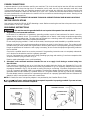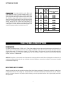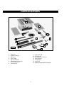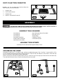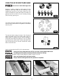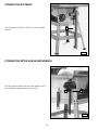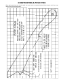
1
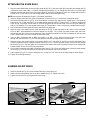
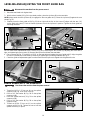
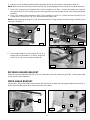
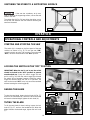
(Model TS350)
PART NO. A05728 - 08-26-05 - Rev. A
Copyright © 2005 Delta Machinery
To learn more about DELTA MACHINERY
visit our website at: www.deltamachinery.com.
For Parts, Service, Warranty or other Assistance,
ESPAÑOL: PÁGINA 29
please call 1-800-223-7278 (In Canada call 1-800-463-3582).
INSTRUCTION MANUAL
10" Table Saw
TABLE OF CONTENTS
IMPORTANT SAFETY INSTRUCTIONS . . . . . . . . . . . . . . . . . . . . . . . . . . . . . . . . . . . . . . . . . . . . . . . . . . . . . . . . . . . . 2
SAFETY GUIDELINES - DEFINITIONS. . . . . . . . . . . . . . . . . . . . . . . . . . . . . . . . . . . . . . . . . . . . . . . . . . . . . . . . . . . . . 3
GENERAL SAFETY RULES . . . . . . . . . . . . . . . . . . . . . . . . . . . . . . . . . . . . . . . . . . . . . . . . . . . . . . . . . . . . . . . . . . . . . 4
ADDITIONAL SPECIFIC SAFETY RULES. . . . . . . . . . . . . . . . . . . . . . . . . . . . . . . . . . . . . . . . . . . . . . . . . . . . . . . . . . . 5
FUNCTIONAL DESCRIPTION . . . . . . . . . . . . . . . . . . . . . . . . . . . . . . . . . . . . . . . . . . . . . . . . . . . . . . . . . . . . . . . . . . . 7
CARTON CONTENTS . . . . . . . . . . . . . . . . . . . . . . . . . . . . . . . . . . . . . . . . . . . . . . . . . . . . . . . . . . . . . . . . . . . . . . . . . 8
ASSEMBLY. . . . . . . . . . . . . . . . . . . . . . . . . . . . . . . . . . . . . . . . . . . . . . . . . . . . . . . . . . . . . . . . . . . . . . . . . . . . . . . . . 10
OPERATION . . . . . . . . . . . . . . . . . . . . . . . . . . . . . . . . . . . . . . . . . . . . . . . . . . . . . . . . . . . . . . . . . . . . . . . . . . . . . . . . 18
TROUBLESHOOTING . . . . . . . . . . . . . . . . . . . . . . . . . . . . . . . . . . . . . . . . . . . . . . . . . . . . . . . . . . . . . . . . . . . . . . . . 26
MAINTENANCE . . . . . . . . . . . . . . . . . . . . . . . . . . . . . . . . . . . . . . . . . . . . . . . . . . . . . . . . . . . . . . . . . . . . . . . . . . . . . 26
SERVICE. . . . . . . . . . . . . . . . . . . . . . . . . . . . . . . . . . . . . . . . . . . . . . . . . . . . . . . . . . . . . . . . . . . . . . . . . . . . . . . . . . . 26
ACCESSORIES . . . . . . . . . . . . . . . . . . . . . . . . . . . . . . . . . . . . . . . . . . . . . . . . . . . . . . . . . . . . . . . . . . . . . . . . . . . . . 27
WARRANTY . . . . . . . . . . . . . . . . . . . . . . . . . . . . . . . . . . . . . . . . . . . . . . . . . . . . . . . . . . . . . . . . . . . . . . . . . . . . . . . . 28
ESPAÑOL . . . . . . . . . . . . . . . . . . . . . . . . . . . . . . . . . . . . . . . . . . . . . . . . . . . . . . . . . . . . . . . . . . . . . . . . . . . . . . . . . . 29
IMPORTANT SAFETY INSTRUCTIONS
Read and understand all warnings and operating instructions before using any tool or equipment.
When using tools or equipment, basic safety precautions should always be followed to reduce the risk of
personal injury. Improper operation, maintenance or modification of tools or equipment could result in serious
injury and property damage. There are certain applications for which tools and equipment are designed. Delta
Machinery strongly recommends that this product NOT be modified and/or used for any application other than
for which it was designed.
If you have any questions relative to its application DO NOT use the product until you have written Delta Machinery
and we have advised you.
Online contact form at www.deltamachinery.com
Postal Mail: Technical Service Manager
Delta Machinery
4825 Highway 45 North
Jackson, TN 38305
(IN CANADA: 125 Mural St. Suite 300, Richmond Hill, ON, L4B 1M4)
Information regarding the safe and proper operation of this tool is available from the following sources:
Power Tool Institute
1300 Sumner Avenue, Cleveland, OH 44115-2851
www.powertoolinstitute.org
National Safety Council
1121 Spring Lake Drive, Itasca, IL 60143-3201
American National Standards Institute, 25 West 43rd Street, 4 floor, New York, NY 10036 www.ansi.org
ANSI 01.1Safety Requirements for Woodworking Machines, and the U.S. Department of Labor regulations www.osha.gov
SAVE THESE INSTRUCTIONS!
2
SAFETY GUIDELINES - DEFINITIONS
It is important for you to read and understand this manual. The information it contains relates to
protecting YOUR SAFETY and PREVENTING PROBLEMS. The symbols below are used to help you
recognize this information.
Indicates an imminently hazardous situation which, if not avoided, will result in death or
serious injury.
Indicates a potentially hazardous situation which, if not avoided, could result in death or serious
injury.
Indicates a potentially hazardous situation which, if not avoided, may result in minor or moderate
injury.
Used without the safety alert symbol indicates potentially hazardous situation which, if not
avoided, may result in property damage.
CALIFORNIA PROPOSITION 65
Some dust created by power sanding, sawing, grinding, drilling, and other construction activities
contains chemicals known to cause cancer, birth defects or other reproductive harm. Some examples of these
chemicals are:
• lead from lead-based paints,
• crystalline silica from bricks and cement and other masonry products, and
• arsenic and chromium from chemically-treated lumber.
Your risk from these exposures varies, depending on how often you do this type of work. To reduce your
exposure to these chemicals: work in a well ventilated area, and work with approved safety equipment, always
wear NIOSH/OSHA approved, properly fitting face mask or respirator when using such tools.
3
GENERAL SAFETY RULES
READ AND UNDERSTAND ALL WARNINGS AND OPERATING INSTRUCTIONS BEFORE
USING THIS EQUIPMENT. Failure to follow all instructions listed below, may result in electric shock, fire,
and/or serious personal injury or property damage.
IMPORTANT SAFETY INSTRUCTIONS
1.
FOR YOUR OWN SAFETY, READ THE INSTRUCTION
MANUAL BEFORE OPERATING THE MACHINE.
Learning the machine’s application, limitations, and
specific hazards will greatly minimize the possibility of
accidents and injury.
2.
WEAR EYE AND HEARING PROTECTION. ALWAYS
USE SAFETY GLASSES. Everyday eyeglasses are NOT
safety glasses. USE CERTIFIED SAFETY EQUIPMENT.
Eye protection equipment should comply with ANSI
Z87.1 standards. Hearing equipment should comply
with ANSI S3.19 standards.
3.
4.
5.
6.
15. SECURE THE WORKPIECE. Use clamps or vise when
you cannot secure the workpiece on the table and
against the fence by hand or when your hand will be
dangerously close to the blade (within 6”).
WEAR PROPER APPAREL. Do not wear loose clothing,
gloves, neckties, rings, bracelets, or other jewelry which
may get caught in moving parts. Nonslip footwear is
recommended. Wear protective hair covering to contain
long hair.
16. FEED THE WORKPIECE AGAINST THE DIRECTION OF
THE ROTATION OF THE BLADE, CUTTER, OR ABRASIVE
SURFACE. Feeding it from the other direction will cause
the workpiece to be thrown out at high speed.
DO NOT USE THE MACHINE IN A DANGEROUS
ENVIRONMENT. The use of power tools in damp or wet
locations or in rain can cause shock or electrocution.
Keep your work area well-lit to prevent tripping or
placing arms, hands, and fingers in danger.
17. DON’T FORCE THE WORKPIECE ON THE MACHINE.
Damage to the machine and/or injury may result.
18. DON’T OVERREACH. Loss of balance can make you
fall into a working machine, causing injury.
MAINTAIN ALL TOOLS AND MACHINES IN PEAK
CONDITION. Keep tools sharp and clean for best and safest
performance. Follow instructions for lubricating and changing
accessories. Poorly maintained tools and machines can
further damage the tool or machine and/or cause injury.
19. NEVER STAND ON THE MACHINE. Injury could occur if
the tool tips, or if you accidentally contact the cutting tool.
20. NEVER LEAVE THE MACHINE RUNNING UNATTENDED.
TURN THE POWER OFF. Don’t leave the machine until it
comes to a complete stop. A child or visitor could be injured.
CHECK FOR DAMAGED PARTS. Before using the
machine, check for any damaged parts. Check for
alignment of moving parts, binding of moving parts,
breakage of parts, and any other conditions that may
affect its operation. A guard or any other part that is
damaged should be properly repaired or replaced.
Damaged parts can cause further damage to the
machine and/or injury.
7.
KEEP THE WORK AREA CLEAN. Cluttered areas and
benches invite accidents.
8.
KEEP CHILDREN AND VISITORS AWAY. Your shop is a
potentially dangerous environment. Children and visitors can
be injured.
9.
14. USE THE PROPER EXTENSION CORD. Make sure
your extension cord is in good condition. When using
an extension cord, be sure to use one heavy enough to
carry the current your product will draw. An undersized
cord will cause a drop in line voltage, resulting in loss
of power and overheating. See the Extension Cord
Chart for the correct size depending on the cord length
and nameplate ampere rating. If in doubt, use the next
heavier gauge. The smaller the gauge number, the
heavier the cord.
21. TURN THE MACHINE “OFF”, AND DISCONNECT THE
MACHINE FROM THE POWER SOURCE before installing
or removing accessories, before adjusting or changing
set-ups, or when making repairs. An accidental start-up
can cause injury.
22. MAKE YOUR WORKSHOP CHILDPROOF WITH
PA D L O C K S , M A S T E R S W I T C H E S , O R B Y
REMOVING STARTER KEYS. The accidental start-up
of a machine by a child or visitor could cause injury.
23. STAY ALERT, WATCH WHAT YOU ARE DOING, AND
USE COMMON SENSE. DO NOT USE THE MACHINE
WHEN YOU ARE TIRED OR UNDER THE INFLUENCE
OF DRUGS, ALCOHOL, OR MEDICATION. A moment of
INATTENTION WHILE OPERATING POWER TOOLS
MAY RESULT IN INJURY.
REDUCE THE RISK OF UNINTENTIONAL STARTING.
Make sure that the switch is in the “OFF” position
before plugging in the power cord. In the event of a
power failure, move the switch to the “OFF” position.
An accidental start-up can cause injury.
24.
10. USE THE GUARDS. Check to see that all guards are in
place, secured, and working correctly to reduce the risk
of injury.
11. REMOVE ADJUSTING KEYS AND WRENCHES
BEFORE STARTING THE MACHINE. Tools, scrap
pieces, and other debris can be thrown at high speed,
causing injury.
12. USE THE RIGHT MACHINE. Don’t force a machine
or an attachment to do a job for which it was not
designed. Damage to the machine and/or injury may
result.
13. USE RECOMMENDED ACCESSORIES. The use of
accessories and attachments not recommended by
Delta may cause damage to the machine or injury to
the user.
4
USE OF THIS TOOL CAN GENERATE
AND DISBURSE DUST OR OTHER AIRBORNE
PARTICLES, INCLUDING WOOD DUST, CRYSTALLINE
SILICA DUST AND ASBESTOS DUST. Direct particles
away from face and body. Always operate tool in well
ventilated area and provide for proper dust removal. Use
dust collection system wherever possible. Exposure to
the dust may cause serious and permanent respiratory
or other injury, including silicosis (a serious lung disease),
cancer, and death. Avoid breathing the dust, and avoid
prolonged contact with dust. Allowing dust to get into
your mouth or eyes, or lay on your skin may promote
absorption of harmful material. Always use properly
fitting NIOSH/OSHA approved respiratory protection
appropriate for the dust exposure, and wash exposed
areas with soap and water.
ADDITIONAL SPECIFIC SAFETY RULES
FAILURE TO FOLLOW THESE RULES MAY RESULT IN SERIOUS PERSONAL INJURY.
1.
DO NOT OPERATE THIS MACHINE until it
is assembled and installed according to the
instructions.
2.
OBTAIN ADVICE FROM YOUR SUPERVISOR,
instructor, or another qualified person if you are not
familiar with the operation of this machine.
3.
FOLLOW ALL WIRING CODES and recommended
electrical connections.
4.
USE THE GUARDS WHENEVER POSSIBLE. Check
to see that they are in place, secured, and working
correctly.
5.
KICKBACK IS THE NATURAL TENDENCY OF
THE WORKPIECE TO BE THROWN BACK AT THE
OPERATOR when the workpiece initially contacts the
blade or if the workpiece pinches the blade. Kickback
is dangerous and can result in serious injury.
6.
AVOID KICKBACK by:
A. keeping blade sharp and free of rust and pitch.
B. keeping rip fence parallel to the saw blade.
C. using saw blade guard and spreader for every
possible operation, including all through sawing.
D. pushing the workpiece past the saw blade prior to
release.
E. never ripping a workpiece that is twisted or
warped, or does not have a straight edge to guide
along the fence.
F. using featherboards when the anti-kickback device
cannot be used.
G. never sawing a large workpiece that cannot be
controlled.
H. never using the fence as a guide when
crosscutting.
I. never sawing a workpiece with loose knots or other
flaws.
ALWAYS USE GUARDS, SPLITTER, AND ANTIKICKBACK FINGERS whenever possible.
7.
REMOVE CUT-OFF PIECES AND SCRAPS from
the table before starting the saw. The vibration of the
machine may cause them to move into the saw blade
and be thrown out. After cutting, turn the machine off.
After the blade has come to a complete stop, remove
all debris.
8.
NEVER START THE MACHINE with the workpiece
against the blade.
9.
NEVER run the workpiece between the fence and a
moulding cutterhead.
10. CUTTING THE WORKPIECE WITHOUT THE USE
OF A FENCE OR MITER GAUGE IS KNOWN AS
“FREEHAND” CUTTING. NEVER perform “free-hand”
operations. Use either the fence or miter gauge to
position and guide the workpiece.
11. HOLD THE WORKPIECE FIRMLY against the miter
gauge or fence.
12. CUTTING COMPLETELY THROUGH THE WORKPIECE IS KNOWN AS “THROUGH-SAWING”. Ripping
and cross-cutting are through-sawing operations.
Cutting with the grain (or down the length of the
workpiece) is ripping. Cutting across the grain (or
across the workpiece) is cross-cutting. Use a fence or
fence system for ripping. DO NOT use a fence or fence
system for cross-cutting. Instead, use a miter gauge.
USE PUSH STICK(S) for ripping a narrow workpiece.
13. AVOID AWKWARD OPERATIONS AND HAND
POSITIONS where a sudden slip could cause a hand
to move into the blade.
14. KEEP ARMS, HANDS, AND FINGERS away from the
blade.
15. NEVER have any part of your body in line with the path
of the saw blade.
16. NEVER REACH AROUND or over the saw blade.
17. NEVER attempt to free a stalled saw blade without first
turning the machine “OFF”.
18. PROPERLY SUPPORT LONG OR WIDE workpieces.
19. NEVER PERFORM LAYOUT, assembly or set-up work
on the table/work area when the machine is running.
20. TURN THE MACHINE “OFF” AND DISCONNECT
THE MACHINE from the power source before installing
or removing accessories, before adjusting or changing
set-ups, or when making repairs.
21. TURN THE MACHINE “OFF”, disconnect the machine
from the power source, and clean the table/work area
before leaving the machine. LOCK THE SWITCH IN
THE “OFF” POSITION to prevent unauthorized use.
22. ADDITIONAL INFORMATION regarding the safe
and proper operation of power tools (i.e. a safety
video) is available from the Power Tool Institute,
1300 Sumner Avenue, Cleveland, OH 44115-2851
(www.powertoolinstitute.com). Information is also
available from the National Safety Council, 1121 Spring
Lake Drive, Itasca, IL 60143-3201. Please refer to
the American National Standards Institute ANSI 01.1
Safety Requirements for Woodworking Machines
and the U.S. Department of Labor OSHA 1910.213
Regulations.
SAVE THESE INSTRUCTIONS.
Refer to them often and use them to instruct others.
POWER CONNECTIONS
A separate electrical circuit should be used for your machines. This circuit should not be less than #12 wire and should
be protected with a 20 Amp time lag fuse. If an extension cord is used, use only 3-wire extension cords which have
3-prong grounding type plugs and matching receptacle which will accept the machine’s plug. Before connecting the
machine to the power line, make sure the switch (s) is in the “OFF” position and be sure that the electric current is of
the same characteristics as indicated on the machine. All line connections should make good contact. Running on low
voltage will damage the machine.
DO NOT EXPOSE THE MACHINE TO RAIN OR OPERATE THE MACHINE IN DAMP LOCATIONS.
MOTOR SPECIFICATIONS
Your machine is wired for 120 volt, 60 HZ alternating current. Before connecting the machine to the power source, make
sure the switch is in the “OFF” position.
GROUNDING INSTRUCTIONS
This machine must be grounded while in use to protect the operator from electric shock..
1. All grounded, cord-connected machines:
In the event of a malfunction or breakdown, grounding provides a path of least resistance for electric current to
reduce the risk of electric shock. This machine is equipped with an electric cord having an equipment-grounding
conductor and a grounding plug. The plug must be plugged into a matching outlet that is properly installed and
grounded in accordance with all local codes and ordinances.
Do not modify the plug provided - if it will not fit the outlet, have the proper outlet installed by a qualified electrician.
Improper connection of the equipment-grounding conductor can result in risk of electric shock. The conductor with
insulation having an outer surface that is green with or without yellow stripes is the equipment-grounding conductor.
If repair or replacement of the electric cord or plug is necessary, do not connect the equipment-grounding conductor
to a live terminal.
Check with a qualified electrician or service personnel if the grounding instructions are not completely understood,
or if in doubt as to whether the machine is properly grounded.
Use only 3-wire extension cords that have 3-prong grounding type plugs and matching 3-conductor receptacles that
accept the machine’s plug, as shown in Fig. A.
Repair or replace damaged or worn cord immediately.
2. Grounded, cord-connected machines intended for use on a supply circuit having a nominal rating less
than 150 volts:
If the machine is intended for use on a circuit that has an outlet that looks like the one illustrated in Fig. A, the
machine will have a grounding plug that looks like the plug illustrated in Fig. A. A temporary adapter, which looks like
the adapter illustrated in Fig. B, may be used to connect this plug to a matching 2-conductor receptacle as shown
in Fig. B if a properly grounded outlet is not available. The temporary adapter should be used only until a properly
grounded outlet can be installed by a qualified electrician. The green-colored rigid ear, lug, and the like, extending
from the adapter must be connected to a permanent ground such as a properly grounded outlet box. Whenever the
adapter is used, it must be held in place with a metal screw.
NOTE: In Canada, the use of a temporary adapter is not permitted by the Canadian Electric Code.
In all cases, make certain that the receptacle in question is properly grounded. If you are not sure,
have a qualified electircian check the receptacle.
GROUNDED OUTLET BOX
GROUNDED OUTLET BOX
GROUNDING MEANS
CURRENT
CARRYING
PRONGS
ADAPTER
GROUNDING BLADE
IS LONGEST OF THE 3 BLADES
Fig. A
Fig. B
6
EXTENSION CORDS
MINIMUM GAUGE EXTENSION CORD
RECOMMENDED SIZES FOR USE WITH STATIONARY ELECTRIC MACHINES
Ampere
Rating
0-6
0-6
0-6
0-6
6-10
6-10
6-10
6-10
10-12
10-12
10-12
10-12
12-16
12-16
12-16
Use proper extension cords. Make sure
your extension cord is in good condition and is a 3wire extension cord which has a 3-prong grounding
type plug and matching receptacle which will accept
the machine’s plug. When using an extension cord, be
sure to use one heavy enough to carry the current of the
machine. An undersized cord will cause a drop in line
voltage, resulting in loss of power and overheating. Fig.
D-1 shows the correct gauge to use depending on the
cord length. If in doubt, use the next heavier gauge. The
smaller the gauge number, the heavier the cord.
Volts
120
120
120
120
120
120
120
120
120
120
120
120
120
120
120
Total
Length of
Cord in
Feet
up to 25
25-50
50-100
100-150
up to 25
25-50
50-100
100-150
up to 25
25-50
50-100
100-150
up to 25
25-50
Gauge of Extension
Cord
18 AWG
16 AWG
16 AWG
14 AWG
18 AWG
16 AWG
14 AWG
12 AWG
16 AWG
16 AWG
14 AWG
12 AWG
14 AWG
12 AWG
GREATER THAN 50 FEET NOT RECOMMENDED
Fig. D-1
FUNCTIONAL DESCRIPTION
FOREWORD
The Delta ShopMaster Model TS350 is a 10" Table Saw designed to give high quality performance with depth-of-cut
capacity up to 2-7/16" (62mm) at 90° for clean cutting of standard stock sizes. This tool includes the basic machine,
a sturdy steel stand, a T-Square fence system, a T-Slot miter gauge, a 10 amp motor, a cast-iron table with extension
wings (22-1/4" x 38-1/2"), a see-thru blade guard with anti-kickback fingers, convenient up-front blade adjusting
controls, and a 10" carbide blade.
NOTICE: The photo on the manual cover illustrates the current production model. All other illustrations contained in the
manual are representative only and may not depict the actual labeling or accessories included. These are are intended
to illustrate technique only.
UNPACKING AND CLEANING
Carefully unpack the machine and all loose items from the shipping container(s). Remove the protective coating from
all unpainted surfaces. This coating may be removed with a soft cloth moistened with kerosene (do not use acetone,
gasoline or lacquer thinner for this purpose). After cleaning, cover the unpainted surfaces with a good quality household
floor paste wax.
7
CARTON CONTENTS
1
2
3
15
4
14
11
5
13
12
6
10
Fig. A
7
9
8
1.
2.
3.
4.
5.
6.
7.
8.
Table Saw
Extension Wing (2)
Rip Fence
Miter Gauge
Rip Fence Handle
Handwheel Lock Knob (2)
M10 Flat Washer (2)
Handwheel (2)
9.
10.
11.
12.
13.
14.
15.
8
Right Front Rail
Left Front Rail
Rail Extension Connector
Right Rear Rail
Left Rear Rail
Saw Blade
Blade Guard and Splitter Assembly
2
1
8
9
333
6
13
7
5
4
16
15
18
20
22
12
14
11
10
17
21
19
Fig. B
For Blade Guard and Splitter Assembly
1. Splitter Bracket
2. 5/8" Flat Washer (2)
3. M12 x 1.75 Hex Nut (2)
4. M6 x 1x20mm Hex Head Screw
5. 1/4" External. Tooth Lockwasher (2)
6. 5/16" Flat Washer (2)
7. M6 x 1 Wing Nut
8. 13mm Open End Wrench
9. 15/16" Hex Arbor Wrench
For Fastening Saw to Stand
14. M8 x 1.25 x 16mm Hex Head Screws (4)
15. 3/8" Flat Washer (8)
16. M8 x 1.25 Hex Nut (4)
For Rear Guide Rail
17. M8 x 1.25x16mm Hex Head Screw (5)
18. M8.4 Flat Washer (5)
19. M8.1 Lockwasher (5)
For Extension Wings
For Front Guide Rail
10. M6 x 1x20mm Carriage Head Screw (5)
11. M6.4 Flat Washer (5)
12. M6.1 Lockwasher (5)
13. M6 x 1 Hex Nut (5)
20. - M8x1.25x16mm Hex Head Screw (6)
21. - 5/16" Lockwasher (6)
22. - 3/8" Flat Washer (6)
1
2
9
20
8
3
5
Fig. C
1. 2. 3. 4. 5. -
4
6
19" Top Front and Rear Braces (2)
22-1/2" Bottom Front and Rear Braces (2)
Stand Legs (4)
Feet (4)
3/8" Flat Washer (32)
6. 7. 8. 9. -
9
M8 x 1.25x16mm Carriage Head Screw (32)
M8 x 1.25 Hex Nut (32)
Bottom Side Braces - 20" in length (2)
Top Side Braces - 16-1/2" in length (2)
DUST COLLECTION CONNECTOR
1
2
3
Do not operate this machine without the
dust collection connector mounted.
1. 2. 3. 4. -
Adapter Plate
Dust Collection Hood
Adapter Plate
#10x1/2" Sheet Metal Screws (4)
2
Fig. D
4
ASSEMBLY
For your own safety, do not connect the machine to the power source until the machine is
completely assembled and you read and understand the entire instruction manual.
ASSEMBLY TOOLS REQUIRED
10mm Wrench
13mm Wrench
19mm Wrench
Flat-Head Screwdriver
Phillips-Head Screwdriver
Arbor Wrench (Provided)
Open-end Arbor Wrench (Provided)
Drill with 1/8" Bit
Straight Edge
Carpenter's Square
Combination Square
ASSEMBLY TIME ESTIMATE
Assembly for this machine takes approximately 2 hours.
ASSEMBLING THE STAND
Assemble the stand (Fig. 1). The braces, legs, and feet are labeled the same in Fig. C and Fig. 1. Insert the M8 x 1.25 x
16 mm carriage head screws through the legs and braces. Place the 3/8" flat washers on the screws. Secure with the
M8 x 1.25 hex nuts. Hand-tighten for future adjustment.
NOTE: The top lips of the two top side braces (A) Fig. 1 must fit on top of the top lips of the front and rear braces (B).
The side braces (A) have holes on top for mounting the saw to the stand.
B
A
A
B
F
C
E
D
D
E
C
Fig. 2
Fig. 1
10
F
DUST COLLECTION CONNECTOR
Do not operate the machine without the dust collector attached.
The TS350 is supplied with a dust collection connector to provide a means of connecting a 4" diameter dust collection
hose to the machine.
A
D
C
Fig. 3
Fig. 4
1. Turn the saw table face down on a piece of cardboard to protect the table surface. Align the four holes in the saw
cabinet with the four holes (A) Fig. 5A in the stand.
2. Align the two holes (A) Fig. 3 in one of the mounting plates (C) with the two holes in the the stand and saw. Place
a 3/8" flat washer on an M8 x 1.25 x 16mm hex head screw. Insert the screw through the hole in the saw, the
stand, and the hole in the mounting plate. Place a 3/8" flat washer and an M8 x 1.25 hex nut on the screw. Tighten
securely. Repeat this process for the remaining hole.
3. Insert the dust collection hood (D) under the mounting plate (Fig. 4).
4. Place the other mounting plate over the dust collection hood. Align the two holes (F) Fig. 5 in the mounting plate
(E) with the two holes in the the stand and saw. Place a 3/8" flat washer on an M8 x 1.25 x 16mm hex head screw.
Insert the screw through the hole in the saw, the stand, and the hole in the mounting plate. Place a 3/8" flat washer
and an M8 x 1.25 hex nut on the screw. Tighten securely. Repeat this process for the remaining hole.
5. Lift the dust collection hood (D) Fig. 6. Use a 1/8" drill bit to drill a pilot hole through one of the dust collection hood
mounting holes (G) in the adapter plate. Thread a #10 x 1/2" sheet metal screw in the hole. Repeat this process for
the three remaining holes (G).
G
F
D
E
Fig. 5
Fig. 6
11
G
ATTACHING THE SAW TO THE STAND.
1. Turn the saw table face down on cardboard to protect the table surface. Align the four holes in the saw cabinet with
the four holes in the stand.
2. Place a 3/8" flat washer on an M8 x 1.25 x 16mm hex head screw. Insert the screw through the hole in the stand
and the hole in the saw. Place a 3/8" flat washer on the screw. Thread an M8 x 1.25 hex nut on the screw. Tighten
securely. Repeat this process for the three remaining holes.
3. Turn saw table face up (Fig. 8).
4. Push on the top of the saw so that the legs of the stand can adjust to the surface of the floor. Tighten all stand
hardware.
BLADE ADJUSTING HANDWHEELS
1. Attach one handwheel (A) Fig. 9 on the blade-raising shaft (B). Engage the slots (C) in the hub of the handwheel with
the roll pin (D) on the shaft.
B
D
A
C
Fig. 9
Fig. 8
F
E
2. Place an M10 flat washer on the end of the shaft.
Thread the lock knob (E) Fig. 10 on the shaft.
G
3. Attach the other handwheel (F) Fig. 10 to the bladetilting shaft in the same manner.
Fig. 10
EXTENSION WINGS
1. Align the three holes in the extension wing (A) Fig. 11
with the three holes in the side of the saw table.
A
NOTE: Hand-tighten the hardware for further adjustment.
Place a 5/16" lockwasher and a 3/8" flat washer on
an M8 x 1.25 x 16mm hex head screw. Insert the
screw through the hole in the extension wing. Thread
the screw into the tapped hole in the side of the saw
table. Repeat this process for the two remaining
holes in the extension wing and the saw table.
B
Fig. 11
12
2. Use a straight-edge (C) Fig. 12 to see if the extension
wing (A) is level with the saw table (D) before
tightening the three screws (B) Fig. 11.
C
D
3. Attach the other extension wing to the opposite side
of the table in the same manner.
A
Fig. 12
SAW BLADE
Disconnect the machine from the power source!
NOTE: Two wrenches are supplied - a box-end and an open-end.
NOTE: Use only 10" saw blades with 5/8" arbor holes that are rated for 3000 RPM or higher
1. Loosen the two screws and remove the table insert
(A) Fig. 13.
L
IMPORTANT: Do not lose the two rubber washers
(L) located under table insert (A).
2. Raise the saw blade to its maximum height by turning
the vertical blade adjusting handwheel counterclockwise. To remove the blade, place the open-end
wrench on the flats of the saw arbor. Use the boxend wrench to turn the arbor nut toward the front of
the saw. Remove the arbor nut (E) and flange (D) from
the saw arbor.
E
D
A
F
Fig. 13
B
L
F
3. Attach the saw blade (C) Fig. 14 to the arbor.
NOTE: Make sure that the teeth of the blade point down
toward the front of the table (Fig. 14). Attach the flange
(D) and arbor nut (E) to the arbor and tighten the arbor
nut (E) by hand, being sure that the saw blade is against
the inner blade flange.
4. Place the provided open end wrench (F) Fig. 14 on
the flats of the arbor to keep the arbor from turning.
Use the other provided wrench (G) to tighten the
arbor nut (E) toward the rear 0f the saw.
C
D
E
Fig. 14
G
Replace the table insert (A) Fig. 15
flush with the table surface.
H
7. Place a straight edge or square (H) Fig. 15 on the saw
table extending over the table insert (A). To adjust,
tighten or loosen the two adjustment screws (K).
K
Fig. 15
13
K
A
D
C
E
F
H
G
A
A
B
Fig. 17
Fig. 16
K
D
F
E
G
H
M
J
L
Fig. 18
Fig. 19
P
X
B
C
V
D
A
D
E
P
E
Fig. 20
W
T
C
S
Fig. 21
14
R
ATTACHING THE GUIDE RAILS
1. Align the three slotted holes in the front right guide rail (A) Fig. 16, with two holes (B) in saw table and slotted hole (C)
in extension wing. Insert a M6 x 1 x 20mm carriage head screw (D) Fig. 14, through the three holes in the front right
guide rail, and the saw table. Place a M6.4 flat washer (E), and a 6.1 lockwasher (F) onto the carriage head screw (D).
Thread an M6 x 1 hex nut (G) onto the carriage head screw (D) and hand tighten only.
NOTE: Hand-tighten all hardware in Steps 1-9 for further adjustment.
2. Insert the longer end of the front guide rail extension connector (H) Fig. 17 into the end of the guide rail (A).
3. Attach the front left guide rail (J) Fig. 18 on the extension connector (H). Align the two slotted holes in the guide rail
extension (J) Fig. 16 with the hole (K) in the table and the extension wing (L). Insert an M6 x 1 x 20mm carriage head
screw (D) Fig. 16 through the two holes in the front left guide rail and the saw table. Place an M6.4 flat washer (E)
and a 6.1 lockwasher (F) on the carriage head screw (D). Thread a M6 x 1 hex nut (G) on the carriage head screw (D).
4. Fig. 19 illustrates the front guide rail loosely attached to the table saw.
5. Align the holes in the longer section of the rear guide rail (P) Fig. 20 with the holes (A), (B), and (C) in the saw table.
Place an M8.1 lockwasherand an M8.4 flat washer on an M8 x 1.25 x 16mm hex head screw. Insert the screw
through the hole (A) Fig. 20 in the rear guide rail. Place an M8.4 flat washer and an M8.1 lockwasher on the hex head
screw. Thread a M8 x 1.25 hex nut onto the hex head screw.
6. Place an M8.1 lockwasher and an M8.4 flat washer on an M8 x 1.25 x 16mm hex head screw. Insert the screw
through the holes (B) and (C) Fig. 20 in the rear guide rail and into the tapped hole in the saw table.
7. Align the holes in the shorter section of rear guide rail (R) Fig. 21, with holes (D) and (E) in the in the saw table. Place
an M8.1 lockwasher and a a M8.4 flat washer onto a M8 x 1.25 x 16mm hex head screw. Insert the screw through
the hole (E) Fig. 21, in the rear guide rail. Place a M8.4 flat washer and a M8.1 lockwasher onto the hex head screw.
Thread a M8x1.25 hex nut onto the hex head screw.
8. Place a M8.1 lockwasher and a M8.4 flat washer onto a M8 x 1.25 x 16mm hex head screw. Insert the screw through
the hole (D) Fig. 18 in the rear guide rail and thread into the tapped hole in the saw table.
9. Use a square (X) Fig. 21 or a ruler to adjust the rail, so that it is 7/16" from top of the table along the entire length.
10. Tighten all mounting hardware.
ASSEMBLING RIP FENCE
1. Insert the handle (A) Fig. 22 into the threaded hole (B) in the rip fence (C)
2. Insert a flat-head screwdriver into the rip fence handle (A) Fig. 23. Tighten the screw.
3. Tighten the hex nut (D) Fig. 23 against the fence body..
A
C
B
A
D
Fig. 22
Fig. 23
15
LEVELING AND ADJUSTING THE FRONT GUIDE RAIL
Disconnect the machine from the power source!
1. Raise the saw blade to its highest level.
2. With the fence handle (A) Fig. 24 in the raised position, place the rip fence (B) on the saw table.
NOTE: Make certain that the rip fence (B) is engaged on the rear guide rail (C). Move the rip fence (B) against the saw
blade (Fig. 25).
3. Carefully move the front guide rail (D) Fig. 25 left or right until the line on the cursor (E) aligns with the zero (“0”)
on the guide rail scale (F). Push the handle (A) down to lock the rip fence in position. Tighten the front guide rail
mounting hardware.
A
E
B
F
C
A
D
Fig. 24
Fig. 25
You can make minor adjustments to the cursor (E) Fig. 26 by loosening the two screws (G), adjusting the cursor left or
right, and tightening the two screws (G). Remove the rip fence and lower the saw blade.
4. Place a square (H) Fig. 27 locked in at 13/16" on the saw table and against the top of guide rail (D). Align the guide
rail until it is parallel to the saw table by loosening or tightening the mounting hardware (K) Fig. 27.
5. Check the guide rail adjustment again to make certain that the rip fence is aligned with the guide rail scale.
E
H
K
G
D
K
Fig. 27
Fig. 26
BLADE GUARD/SPLITTER ASSEMBLY
Disconnect the machine from the power source!
1. Thread an M12 x 1.75 hex nut (A) on the splitter
support rod (R) Fig. 28 as far as it will go.
2. Place a 5/8" flat washer (B) Fig. 28 on the splitter
support rod (R).
3. Place the splitter bracket (C) Fig. 28 on the splitter
support rod (R).
4. Place a 5/8" flat washer (B) Fig. 28 on the splitter
support rod (R).
5. Thread an M12x1.75 hex nut (D) on the splitter
support rod (R) Fig. 28. Tighten the nut to hold the
splitter bracket (C) in place.
B
R
A
C
Fig. 28
16
6. Align the hole in the blade guard and splitter assembly (E) Fig. 29 with the hole in the splitter bracket (C).
NOTE: Make certain that the two protrusions (pins)(G) Fig. 30 are engaged with the channel of the splitter assembly.
7. Place a 1/4" external tooth lockwasher and a 5/16" lockwasher on an M6 x 1 x 20mm hex head screw. Insert the
hex head screw (D) Fig. 29 through the hole in the support bracket, then through the slot in the blade guard/splitter
assembly.
8. Place a 1/4" external tooth lockwasher and a 5/16" lockwasher on an M6 x 1 x 20mm hex head screw (D) Fig. 29.
Thread an M6 x 1 wing nut (F) Fig. 30 on the end of the hex head screw.
NOTE: Before tightening the wing nut (F) Fig. 28, leave at least a 1/8" gap between the bottom edge of splitter (N) and
top surface of table (P).
N
C
E
P
G
D
F
Fig. 30
Fig. 29
R
E
9. Use a straight edge to see if the splitter (E) Fig. 31 is
aligned with the saw blade (R). To adjust, loosen the
nut (A) Fig. 31 and move or rotate the splitter (E).
A
Fig. 31
RIP FENCE HOLDER BRACKET
Attach the rip fence holder bracket (A) Fig. 32 to the right side of the saw cabinet using two M5 x 12mm sheet metal
screws and two M5 lockwashers.
MITER GAUGE BRACKET
Use four M5 x 12mm sheet metal screws and two M5 lockwashers to attach the miter gauge holder bracket (A) Fig. 33
and the wrench holder bracket (B) to the left side of the saw cabinet.
A
B
Fig. 32
Fig. 33
17
A
FASTENING THE STAND TO A SUPPORTING SURFACE
If the saw has a tendency to tip over,
slide, or walk on the supporting surface, secure the saw
stand to the floor.
A
The rubber feet (A) Fig. 34 have holes that allow you to
mount the saw stand to the floor without removing the
saw from the stand.
Fig. 34
OPERATION
OPERATIONAL CONTROLS AND ADJUSTMENTS
STARTING AND STOPPING THE SAW
The switch (A) is located on the front panel of the saw
cabinet, as shown in Fig. 35. To turn the saw “ON”,
move the switch up to the “ON” position. To turn the saw
“OFF”, move the switch down to the “OFF” position.
A
Fig. 35
LOCKING THE SWITCH IN THE “OFF” POSITION
IMPORTANT: When the tool is not in use, the switch
should be locked in the “OFF” position to prevent
unauthorized use. Grasp the switch toggle (B) and
pull it out (Fig. 36). With the switch toggle (B) removed
the switch will not operate. However, should the switch
toggle be removed while the saw is in operation, the
saw can be turned “OFF” once, but cannot be restarted
without inserting the switch toggle (B).
B
Fig. 36
RAISING THE BLADE
D
B
To raise the saw blade, loosen the lock knob (A) Fig. 37,
and turn the handwheel (B) clockwise. When the blade
achieves the desired height, tighten the lock knob (A).
C
TILTING THE BLADE
A
To tilt the saw blade for bevel cutting, loosen the lock
knob (C) Fig. 37, and turn the handwheel (D). When the
blade achieves the desired angle, tighten the lock knob
(C).
Fig. 37
18
ADJUSTING THE 90° AND 45° POSITIVE STOPS
Disconnect the machine from the power source!
Your saw is equipped with positive stops that will rapidly position the blade at 90° and 45° to the table. To check and
adjust the positive stops:
1. Turn the handwheel that tilts the blade clockwise as far as it will go. Make sure that the table insert is level
with the table. Place a square (A) Fig. 38 on the table against the blade. See if the blade is 90° to the table.
If not, then loosen the set screws (B) Fig. 40 back off the collar (C), and turn the handwheel until the blade
is at 90° to the table. Adjust the collar (C) Fig. 40 so that it contacts the bracket (D) when the blade is set correctly.
Tighten the set screws (B).
3. Turn the handwheel that tilts the blade counter-clockwise as far as it will go. Place a combination square (A) Fig. 39
on the table and against the blade. See if the blade is 45° to the table. If not, then lightly loosen the two locknuts (E)
Fig. 40, and turn the handwheel until the blade is 45° to the table. Adjust the locknuts (E) Fig. 40 so that the inside
nut contacts the bracket (D) when the blade is set correctly.
E
D
B
Fig. 38
Fig. 39
Fig. 40
FENCE OPERATION/ADJUSTMENTS
Properly align the rip fence with the miter gauge slot to prevent kickback.
1. To move the fence (A) Fig. 41 along the guide rails, lift the fence locking lever (B) and slide the fence to the desired
location on the guide rails. Push the locking lever down (B) to lock the fence in position.
2. You must adjust the fence (A) Fig. 41 so that it is parallel to the miter gauge slots (C). To check and adjust, move the
fence (A) until the bottom edge is in line with the edge of one of the miter gauge slots. Push the fence-locking lever
(B) down. See if the fence (A) is parallel to the edge of the miter gauge slot (C) for the entire length of the table. To
adjust, slightly tighten or loosen one of the two adjusting screws (D) or (E) Fig. 42. Check again. Adjust and check
until you are sure the fence is parallel with the miter gauge slot.
IMPORTANT: Do not remove the rip fence from the guide rail while making this adjustment. Very little movement of the
screws (D) and (E) Fig. 42 is necessary.
A
D
C
B
E
Fig. 41
Fig. 42
19
H
3. The witness line (F) Fig. 43, located on the cursor
(G), shows the distance from the fence to the blade.
To adjust the cursor (G), make a test cut with the
fence locked in position. Measure the width of your
finished cut. Loosen the two screws (H), and adjust
the cursor (G) until the witness line (F) is aligned with
the same marking on the scale (K) as the finished
cut. Tighten the two screws (H).
F
Fig. 43
G
K
MITER GAUGE OPERATION AND ADJUSTMENTS
1. Your miter gauge is equipped with individually adjustable index stops at 90° and 49° right and left. Make
adjustments to these stops by loosening the lock nuts (A) Fig. 44 and tightening or loosening the three adjusting
screws (B) against the stop link (C).
2. To operate the miter gauge, loosen the lock handle (D) Fig. 44 and move the body of the miter gauge (E) to the
desired angle. The miter gauge body will stop at 90° and 45° both right and left. To rotate the miter gauge body past
these points, flip the stop link (C) out of the way.
3. The miter gauge bar is equipped with a special washer (F) Fig. 45, and a flat head screw (G) that are attached to the
bottom end of the miter gauge bar (H). The special washer (F) rides in the T-slotted miter gauge slot (J) and prevents
the miter gauge from falling when it is extended beyond the saw table.
D
E
H
C
B
A
J
G
F
Fig. 45
Fig. 44
ADJUSTING THE TABLE INSERT
Adjust the table insert (A) Fig. 47 so that it is flush with
the saw table surface. Place a straight edge or square
(B) on the saw table extending over the insert. To adjust,
tighten or loosen the two adjusting screws (C).
A
C
Fig. 47
20
B
MACHINE USE
Common sawing operations include ripping and crosscutting. As with all power machines, a certain amount of danger
is involved with the operation and use of the machine. Using the machine with the respect and caution will considerably
lessen the possibility of personal injury. However, if normal safety precautions are overlooked or completely ignored,
personal injury can result. The following information describes the safe and proper method for performing the most
common sawing operations.
The use of attachments and accessories not recommended by delta may result in the risk of
injury.
CROSS-CUTTING
Cross-cutting requires the use of the miter gauge to position and guide the work. Place the work against the miter gauge
and advance both the gauge and the work toward the saw blade (Fig. 48). You can use the miter gauge in either table
slot. When bevel cutting (blade tilted), use the right miter gauge slot so that the blade tilts away from the miter gauge
and your hands.
Start the cut slowly and hold the work firmly against the miter gauge and the table.
During the operation of the saw, never hold or touch a free piece of work. Hold the supported piece, not
the free piece. Never pick up any short length of free work from the table while the saw is running. Never touch a cutoff
piece unless it is at least a foot long.
Continue your feed until the cut is complete. Before pulling the work back, give the workpiece a little sideways shift to
move the work slightly away from the saw blade. Pull the miter gauge and the workpiece back to the starting point.
For added safety and convenience, fit the miter gauge with an auxiliary wood-facing (C) Fig. 49. Make this facing at least
1" higher than the maximum depth of cut, and 12" or more to one side or the other, depending on the miter gauge slot
used. Fasten this auxiliary wood-facing (C) to the front of the miter gauge with two wood screws (A) through the holes
provided in the miter gauge body.
A
C
Fig. 48
Fig. 49
Never use the fence as a cut-off gauge when cross-cutting.
To cross-cut a number of pieces to the same length,
clamp a block of wood (B) Fig. 50 to the fence. Use this
wood as a cut-off gauge.
IMPORTANT: Position this block of wood in front of
the saw blade (Fig. 55). Once the cut-off length is
determined, secure the fence and use the miter gauge to
feed the work into the cut.
B
This block of wood allows the cut-off piece to move
freely along the table surface without binding between
the fence and the saw blade, lessening the possibility of
kickback and/or injury.
Fig. 50
Make sure that the wood block is positioned so that the workpiece is clear of the block before it engages
the blade.
21
RIPPING
Ripping is the operation of making a
lengthwise cut through a board (Fig. 51) Use the rip fence
(A) to position and guide the work. Place the workpiece
so that one edge rides against the rip fence while the flat
side of the board rests on the table. Since the work is
pushed along the fence, it must have a straight edge and
make solid contact with the table. Use the saw guard.
The guard has anti-kickback fingers to prevent kickback,
and a splitter to prevent the wood kerf from closing and
binding the blade.
A
Fig. 51
Start the motor and advance the work, holding it down
and against the fence.
Never stand in the line of the saw cut
when ripping.
Hold the work with both hands and push it along the
fence and into the saw blade (Fig. 51). Feed the work
through the saw blade with one or two hands. After the
work is beyond the saw blade and anti-kickback fingers,
remove your hand from the work. The work will either
stay on the table, tilt up slightly and be caught by the
rear end of the guard, or slide off the table to the floor.
Alternately, you can continue the feed to the end of the
table. Lift the work and bring it back along the outside
edge of the fence. Leave the cut-off stock on the table.
Do not touch it until the saw blade stops. When ripping
boards longer than three feet, use a work support at the
rear of the saw to keep the workpiece from falling off the
saw table.
Fig. 52
If the ripped work is less than 4 inches wide, use a push
stick to complete the feed (Fig. 52). The push stick can
be made from scrap material as explained in the section
“CONSTRUCTING A PUSH STICK.” When ripping
material under 2 inches in width, a use a flat pushboard
since ordinary push sticks may interfere with the blade
guard. The flat pushboard can be made as shown in Fig.
53.
Fig. 53
U S I N G A N A U X I L I A RY W O O D
FACING ON THE RIP FENCE
When performing special operations (moulding cutterhead,
etc.), add a wood facing (A) Fig. 54 to one or both sides
of the rip fence. Attach the wood facing to the fence with
wood screws through the holes provided in the fence.
Stock that is 3/4' thick is suitable for most work, although
an occasional job may require 1" facing.
A
Use the wood facing when ripping thin material (paneling,
etc.) to prevent the workpiece from catching between the
bottom of the rip fence and the saw table surface.
Fig. 54
22
USING THE ACCESSORY DADO HEAD
Do not use a dado blade larger than
6" in diameter.
Dadoing is cutting a rabbet or wide groove into the
workpiece. Most dado head sets are made up of two
outside saws and four or five inside cutters (Fig. 58).
Various combinations of saws and cutters are used to cut
grooves from 1/8" to 13/16" for use in shelving, making
joints, tenoning, grooving, etc.
Fig. 58
The cutters are heavily swaged and must be arranged so
that this heavy portion falls in the gullets of the outside
saws (Fig. 59).
Fig. 59
The saw and cutter overlap is shown in Fig. 60 with (A)
being the outside saw, (B) an inside cutter, and (C) a
paper washer or washers that are used as needed to
control the exact width of the groove. Cut a 1/4" groove
by using the two outside saws. Position the teeth of the
saws so that the raker on one saw is beside the cutting
teeth on the other saw.
A
B
C
Fig. 60
Attach the dado head set (D) Fig. 61 to the saw arbor.
Use the accessory dado table insert (E) Fig. 67 in place of the standard table insert.
The blade guard and splitter assembly cannot be used when dadoing.
A typical dado operation using the miter gauge as a guide is shown in Fig. 62.
Never use the dado head in the bevel position.
Always install the blade guard after the operation is completed.
D
A
E
Fig. 62
Fig. 61
23
STORING THE RIP FENCE
You can store the rip fence (B) Fig. 63 on the holder
bracket.
B
Fig. 63
STORING THE MITER GAUGE AND WRENCH
The two holder brackets hold the miter gauge (C) and
and the blade changing wrenches (D) Fig. 64.
D
A
Fig. 64
24
25
1/2" SQUARES
CUT OFF HERE TO
PUSH 1/2" WOOD
CUT OFF HERE TO
PUSH 1/4" WOOD
NOTCH TO HELP
PREVENT HAND
FROM SLIPPING
MAKE FROM 1/2" OR 3/4"
WOOD OR THICKNESS
LESS THAN WIDTH OF
MAT’L. TO BE CUT
PUSH STICK
CONSTRUCTING A PUSH STICK
When ripping work less than 4 inches wide, use a push stick to complete the feed. Make this push stick from scrap
material using the following pattern.
TROUBLESHOOTING
For assistance with your machine, visit our website at www.deltamachinery.com for a list of service centers or call the
DELTA Machinery help line at 1-800-223-7278 (In Canada call 1-800-463-3582).
MAINTENANCE
KEEP MACHINE CLEAN
LUBRICATION
Periodically blow out all air passages with dry compressed
air. All plastic parts should be cleaned with a soft damp
cloth. NEVER use solvents to clean plastic parts. They
could possibly dissolve or otherwise damage the material.
Apply household floor paste wax to the machine table
and extension table or other work surface weekly.
PROTECTING CAST IRON FROM RUST
To clean and protect cast iron tables from rust, you will
need the following materials: 1 pushblock from a jointer,
1 sheet of medium Scotch-Brite™ Blending Hand Pad,
1 can of WD-40®, 1 can of degreaser, 1 can of TopCote®
Aerosol. Apply the WD-40® and polish the table surface
with the Scotch-Brite pad using the pushblock as a
holddown. Degrease the table, then apply the TopCote®
accordingly.
WEAR ANSI Z87.1 SAFETY GLASSES
WHILE USING COMPRESSED AIR.
FAILURE TO START
Should your machine fail to start, check to make sure
the prongs on the cord plug are making good contact
in the outlet. Also, check for blown fuses or open circuit
breakers in the line.
SERVICE
deltamachinery.com for a list of service centers or call
the Customer Care Department at 1-800-223-7278. All
repairs made by our service centers are fully guaranteed
against defective material and workmanship. We cannot
guarantee repairs made or attempted by others. Should
you have any questions about your tool, feel free to write
us at any time. In any communications, please give all
information shown on the nameplate of your tool (model
number, type, serial number, etc.).
REPLACEMENT PARTS
When servicing use only identical replacement parts. Check
the parts list included for more information. Parts lists can
also be found online at www.deltamachinery.com.
SERVICE AND REPAIRS
All quality tools will eventually require servicing, or
replacement of parts due to wear from normal use. For
assistance with your tool, visit our website at www.
26
ACCESSORIES
A complete line of accessories is available from your Delta Supplier, Porter-Cable • Delta Factory Service Centers, and
Delta Authorized Service Stations. Please visit our Web Site www.deltamachinery.com for a catalog or for the name of
your nearest supplier.
Since accessories other than those offered by Delta have not been tested with this product, use
of such accessories could be hazardous. For safest operation, only Delta recommended accessories should be
used with this product.
27
WARRANTY
To register your tool for warranty service visit our website at www.deltamachinery.com.
Two Year Limited New Product Warranty
Delta will repair or replace, at its expense and at its option, any new Delta machine, machine part, or machine accessory
which in normal use has proven to be defective in workmanship or material, provided that the customer returns the
product prepaid to a Delta factory service center or authorized service station with proof of purchase of the product within
two years and provides Delta with reasonable opportunity to verify the alleged defect by inspection. For all refurbished
Delta product, the warranty period is 180 days. Delta may require that electric motors be returned prepaid to a motor
manufacturer’s authorized station for inspection and repair or replacement. Delta will not be responsible for any asserted
defect which has resulted from normal wear, misuse, abuse or repair or alteration made or specifically authorized by
anyone other than an authorized Delta service facility or representative. Under no circumstances will Delta be liable
for incidental or consequential damages resulting from defective products. This warranty is Delta’s sole warranty and
sets forth the customer’s exclusive remedy, with respect to defective products; all other warranties, express or implied,
whether of merchantability, fitness for purpose, or otherwise, are expressly disclaimed by Delta.
28