1
CCCJc:~lA~m
r:»~OFESSIONAI
SE~IES
Autom atic I Manual Transm ission
Remot e Start with Keyles s Entry
Installa tion Guide
for models :
ca55 53ss t
2012 Audiovox Electronics Corporation. All rights reserved.
4280478
Table of Contents
Before You Begin ...................................................................................... 3
Wire Connection Guide ........................................................................... 4
11 Pin Main Harness ................................................................................. 5
3 Pin Parking Light Harness ..................................................................... 8
6 Pin Start Harness ................................................................................... 9
4 Pin Alternate Harness .......................................................................... 10
2 Pin Door Lock Harness ........................................................................ 11
Add it ion a I Ports ...................................................................................... 15
Antenna I LED I Programming Port ....................................................... 15
DBIPort .................................................................................................... 15
Telematic Interface Port .......................................................................... 15
Set Up & Programming .......................................................................... 16
Transmitter Programming ........................................................................ 16
Manual Feature Programming ................................................................. 16
Programming Feature Banks .................................................................. 17
Tach Programming .................................................................................. 19
Smart Tach less Mode ............................................................................. 19
Feature Descriptions ............................................................................. 20
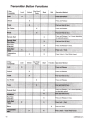
Transmitter Button Functions ............................................................. 26
Remote Start Shutdown Diagnostics ................................................ 27
System Layout ......................................................................................... 28
2
ca5553sst rev A
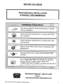
BEFORE YOU BEGIN
PROFESSIONAL INSTALLATION
STRONGLY RECOMMENDED
Roll down window to avoid locking keys in vehicle
during installation
Avoid mounting components or routing wires near
hot surfaces
Avoid mounting components or routing wires near
moving parts
Tape or loom wires under hood for protection and
appearance
Use a Digital Multi Meter for testing and verifying
circuits. DO NOT USE A TEST LIGHT, OR
"COMPUTER SAFE PROBE" as these can set off air
bags or damage vehicle computers.
Technical Support (800) 421-3209
..•..
or go to
http://techservices.codesystems.com
2012 Audiovox Electronics Corporation. All rights reserved.
3
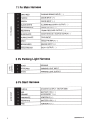
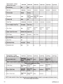
11 Pin Main Harness
GRAY/RED
PARKING BRAKE INPUT (- )
PURPLE
DOOR INPUT ( +)
GREEN
DOOR INPUT ( - )
BLACK/WHITE
ILLUMINATED ENTRY OUTPUT ( - )
BROWN/B LACK
HORN OUTPUT ( - )
z
RED/WHITE
TRUNK RELEASE OUTPUT ( - )
~
BLUE/BLA CK
START STATUS I ACTIVE OUTPUT ( - )
PURPLE/WHITE
TACH INPUT
GRAY
HOOD PIN INPUT ( - )
BROWN/R ED
BRAKE INPUT ( + )
VIOLET/BLACK
AUX 1 OUTPUT (-)
z
<(
~
a..
~
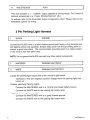
3 Pin Parking Light Harness
(/)
zr-:x:
a..(!)
BLACK
GROUND
WHITE/RED
PARKING LIGHT INPUT
WHITE
PARKING LIGHT OUTPUT
('f) -
.....J
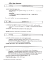
6 Pin Start Harness
PURPLE
STARTER OUTPUT- MOTOR SIDE
RED
BATTERY 12V ( +)
r(/)
ORANGE
ACCESSORY 1 ( + )
z
PINK/WHITE
IGNITION 2 ( + )
<0
RED/WHITE
BATTERY 12V ( +)
PINK
IGNITION 1 ( +)
r-
0:::
<(
a..
4
ca5553sst rev A
4 Pin Alternate Harness
BLACK/YE LLOW
PULSE DURING CRANK ( - )
GREEN/WHITE
PULSE AFTER SHUTDOWN ( - )
LT BLUE
FACTORY ARM I PULSE AFTER START ( - )
LT GREEN/BL ACK
FACTORY DISARM I PULSE BEFORE START ( - )
2 Pin Door Lock Harness
z~
-(.)
BLUE
UNLOCK (-)
C\I_..J
GREEN
LOCK (-)
a..
a
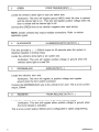
11 Pin Main Harness
1
GRAY/RED
PARKING BRAKE INPUT (-)
Locate the vehicle's parking brake wire.
Verification: This wire will register ground when the vehicle's PARKING
BRAKE is engaged.
NOTE: The following connect ion is required for Manual Transmission
Mode.
2
PURPLE
DOOR TRIGGER INPUT ( +)
Locate the vehicle's dome light or door pin switch wire.
Verification: This wire will register positive voltage (POS) when the door is
opened and the interior light is on. This wire will
register ground or "0" Volts when the door is closed and the interior light is
off.
Connect the PURPLE wire to the vehicle's positive door input wire(s).
NOTE: Certain vehicles may require multiple connections. Refer to vehicle
application guide.
2012 Audiovox Electronics Corporation. All rights reserved.
5
3
GREEN
DOOR TRIGGER INPUT ( - )
Locate the vehicle's dome light or door pin switch wire.
Verification: This wire will register ground (NEG) when the door is opened
and the interior light is on. This wire will register positive voltage when the
door is closed and the interior light is off.
Connect the GREEN wire to the vehicle's negative door input wire(s).
NOTE: Certain vehicles may require multiple connections. Refer to vehicle
application guide.
4
BLACK/WHITE
ILLUMINATED ENTRY OUTPUT (-)
This wire provides a ( - ) 500mA output for 30 seconds when the system is
disarmed capable of driving relays.
Locate the vehicle's dome light or pin switch wire.
Verification: This wire will register positive voltage or ground when the
vehicle's dome light is turned ON.
5
BROWN/BLACK
HORN OUTPUT ( - )
Locate the vehicle's horn wire.
Verification: This wire will register at positive voltage and register
ground when the horn switch is pressed.
Connect the BROWN/BLACK wire to the vehicle's horn wire. This is a low current
output, 500mA.
6
RED!WHITE
TRUNK RELEASE OUTPUT (-)
Locate the vehicle's trunk release wire at the trunk release switch.
Verification: This wire will register either positive voltage or ground when
the trunk release is activated.
This is a low current output, 500mA and is configurable in option programming.
6
ca5553sst rev A
7
BLUE/BLACK
START STATUS I ACTIVE OUTPU T (-)
This wire provides a ground output when the remote start function is activated
and remains until 4 seconds after the remote start is shutdown. If this wire will
be used for multiple application's a 1 amp diode is required in-line with the stripe
facing the control module.
8
PURPLE!WHITE
TACH INPUT
Locate the vehicle's ignition coil or fuel injector in the engine compartment.
Verification: Test using the following procedure:
1.
2.
3.
4.
5.
Set voltmeter to AC VOLTS.
Attach positive lead of a volt meter to a constant 12-volt source.
Attach negative lead of a volt meter to the wire to be tested.
Start the engine.
Have someone press on the gas pedal slightly as you monitor the meter. If
connected to the correct wire, the voltage reading will increase as the engine's
RPM increases.
Connect the PURPLE/WHITE wire to the negative side of the vehicle ignition coil
or fuel injector.
9
GRAY
HOOD PIN INPUT (-)
Install a Hood Pin Switch and connect to the GRAY wire. This connection is
required for Remote Start.
Verification: This wire when connected will register ground when the
vehicle's hood is opened.
Connect the GRAY wire to the hood pin.
NOTE: Be sure to loom the wire, and seal the grommet.
10
BROWN/RED
BRAKE INPUT ( +)
Locate the vehicle's brake light wire at the brake pedal mounted switch. This
connection is required for Remote Start.
Verification: This wire registers positive voltage when the brake pedal is
pressed.
Connect the BROWN/RED wire to the vehicle's brake light wire.
2012 Audiovox Electronics Corporation. All rights reserved.
7
11
VIOLET/BLACK
AUX 1
This wire provides a ( - ) 500mA output capable of driving relays. For Control of
optional accessories (i.e. Power Window/Sunroof, etc.).
To activate refer to the transmitter button configuration chart. Please refer to the
selectable options for timing.
3 Pin Parking Light Harness
1
BLACK
GROUND
Connect the BLACK wire to a solid chassis ground point using a ring terminal and
self tapping screw (not supplied). Scrape away paint from the grounding point to
ensure a good connection. The recommended grounding point is a metal surface
in the driver's side kick panel area.
NOTE: Do not ground the BLACK wire with any other vehicle components.
2
WHITE/RED
PARKING LIGHT INPUT
3
WHITE
PARKING LIGHT OUTPUT
Locate the parking light output wire at the vehicle's light switch.
Verification: This wire registers positive voltage when the parking lights are
turned on.
Positive switching Parking Lights:
Connect the WHITE/RED wire to a 15 Amp max fused battery source.
Connect the WHITE wire to the parking light output wire.
Negative switching Parking Lights:
Connect the WHITE/RED wire to a good chassis ground.
Connect the WHITE wire to the parking light output wire.
8
ca5553sst rev A
6 Pin Start Harness
1
PURPLE
STARTER OUTPUT ( + )
Locate the vehicle starter wire.
Verification: This wire registers voltage only when the key is turned to the
START position.
Verification :
The starter wire registers voltage when the key is turned to the
START position.
Connect the PURPLE wire to the vehicle starter wire.
2
RED
BATTERY 12V ( + )
Locate 1 of the vehicle's constant 12 Volt battery wires at the ignition switch.
Verification: This wire will register ( + ) voltage in all positions of the ignition
switch.
Connect the RED wire to the constant 12 Volt battery wire.
NOTE: Remove all fuses until all connections are made.
3
ORANGE
ACCESSOR Y 1 ( + )
Locate the vehicle's accessory wire at the ignition switch.
Verification: This wire registers voltage when the key is turned to ACC
(Accessory) and the ON (or RUN) position. The voltage drops out when the
key is turned to the START (or CRANK) position.
Connect the ORANGE wire to the vehicle's accessory wire.
4
PINK/WHIT E
IGNITION 2 ( + )
Locate the vehicle's 2nd ignition wire at the ignition switch (if equipped).
Verification: This wire registers voltage when the key is turned to the ON (or
RUN) position, but not the ACC (Accessory) position. The voltage does not
drop out when the key is turned to the START (or CRANK) position.
Connect the PINK/WHITE wire to the vehicle's ignition 2 wire.
Programmable output:
IGN, ACC, Start.
2012 Audiovox Electronics Corporation. All rights reserved.
9
5
RED!WHITE
BATTERY 12V ( + )
Locate 1 of the vehicle's constant 12 Volt battery wires at the ignition switch.
Verification: This wire will register ( + ) voltage in all positions of the ignition
switch.
Connect the RED/WHITE wire to the constant 12 Volt battery wire.
NOTE: Remove all fuses until all connections are made.
6
PINK
IGNITION 1 ( +)
Locate the vehicle's ignition wire at the ignition switch.
Verification: This wire registers voltage when the key is turned to the ON (or
RUN) position. The voltage does not drop out when the key is turned to the
START (or CRANK) position.
Connect the PINK wire to the vehicle's Ignition wire.
This wire is also used for Ignition 1 Output.
4 Pin Alternate Harness
1
BLACKNELLOW
PULSE DURING CRANK (-)
Locate the vehicle's second starter (crank) wire at the ignition switch. (if equipped)
Verification: This wire registers voltage only in the start (crank) position of
the ignition switch.
Connect the BLACK/YELLOW wire as shown in the diagram below. Use an SPOT
relay (not supplied).
This output is configurable in option programming.
2
GREEN/WHITE
PULSE AFTER SHUTDOWN (-)
This wire will supply a ( - ) 500mA pulse after the remote start shuts down. This
is typically used to re-lock the vehicle's doors if they unlock upon remote start
shutdown. It can also be used to pulse a door pin-switch wire to prevent the
vehicle's accessories from remaining on after remote start shutdown.
This output is configurable in option programming.
10
ca5553sst rev A
3
LTBLUE
FACTORY ARM I
PULSE AFTER START (-)
This wire will supply a (-) 500mA pulse both upon arming the system and upon
successful completion of the remote start activation sequence and is typically
used to re-lock the vehicle's doors upon remote start if necessary.
This output is configurable in option programming.
4
LT GREEN/BLACK
FACTORY DISARM I
PULSE BEFORE START (-)
This wire will supply a ( - ) 500mA pulse both upon disarming the system and when
the remote start feature is activated. Locate the factory perimeter alarm disarm
wire from the key cylinder inside the drivers door.
Verification: This wire registers ground if the key is turned to the unlock
position in the driver's door cylinder.
This output is configurable in option programming.
2 Pin Door Lock Harness
1
BLUE
UNLOCK (-)
2
GREEN
LOCK (-)
The door lock I unlock outputs are designed to control several different types of
systems which may require additional parts. Please review the wire and location
chart to see which type of door lock system is in your vehicle. The most common
types are shown in the following diagrams.
2012 Audiovox Electronics Corporation. All rights reserved.
11
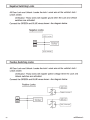
Negative Switching Locks
All Door Lock and Unlock: Locate the lock I unlock wire at the vehicle's lock I
unlock switch.
Verification: These wires will register ground when the Lock and Unlock
switches are activated.
Connect the GREEN and BLUE wires shown in the diagram below.
Negative Locks:
GREEN(-) Lock Output
Vehicle Door Lock
Control Relays
BLUE(-) Unlock Output
Positive Switching Locks
All Door Lock and Unlock: Locate the lock I unlock wire at the vehicle's lock I
unlock switch.
Verification: These wires will register positive voltage when the Lock and
Unlock switches are activated.
Connect the GREEN and BLUE wires shown in the diagram below.
Positive Locks:
GREEN(-) Lock Output
Vehicle Door Lock
Control Relays
BLUE(-) Unlock Output
12
ca5553sst rev A
Reverse Polarity Locks (S-Wire Door locks)
All Door Lock and Unlock: Locate the lock I unlock wire at the vehicle's lock I
unlock switch.
Verification: These wires will rest at ground and register positive
voltage when the Lock and Unlock switches are activated.
Connect the GREEN and BLUE or BLUE/GREEN wires shown in the diagram
below using (2) SPOT relays (not supplied).
Reverse Polarity Locks:
GREEN(-) Lock Output
BLUE (-) Unlock Output
--------~
To Door Lock Motor
Cut
Negative Multiplexed Locks
All Door Lock and Unlock: Locate the lock I unlock wire at the vehicle's lock I
unlock switch.
Verification: This wire will show variable ground when the switch is activated.
Please consult the wire and location chart for specific resistor values for
your vehicle.
Connect the GREEN and BLUE or BLUE/GREEN wires shown in the diagram
below using (2) SPOT relays (not supplied).
Multiplex Locks:
2012 Audiovox Electronics Corporation. All rights reserved.
13
Positive Multiplexed Locks
All Door Lock and Unlock: Locate the lock I unlock wire at the vehicle's lock I
unlock switch.
Verification: This wire will show variable positive voltage when the switch is
activated. Please consult the wire and location chart for specific resistor
values for your vehicle.
Connect the GREEN and BLUE or BLUE/GREEN wires shown in the diagram
below using (2) SPOT relays (not supplied).
Multiplex Locks:
Vehicle Door Lock
Control Relays
Adding Aftermarket Actuators
After installing aftermarket actuators, (not supplied). Connect the GREEN and
BLUE wires shown in the diagram below using (2) SPOT relays (not supplied).
---------1 Fused +12 Volt
87
Battery Source
.------4111..._----1 Fused + 12 Volt
87
Battery Source
BLUE (-) Unlock Output
14
ca5553sst rev A
Additional Ports
Antenna I LED I Programming Port
Mount the supplied antenna/receiver to a clear spot on the vehicle's windshield
that will not block the driver's vision. A good location is usually high on the
windshield near the rear view mirror. Be careful not to mount the antenna/receiver
on any metallic window film, as this will effect system range. Route the antenna/
receiver cable to the control module and plug into the antenna port.
Data Bus Interface Port
This 4 pin port is used for Flashlogic Door Lock and Transponder Databus
Interfaces to communicate with the vehicle's Databus. When using the OBI port to
control the Flashlogic Door Lock and Transponder Interface modules the
following options may be available. Please refer to the 020 (Data to Data)
function list available per vehicle on the tech service web site.
Tach Input
Brake Safety Shut Down
Trunk/Hatch Open
Diesel Glow Plug Input
Door Lock Control
Passlock I Passkey Interface (GM Only)
Dome Light Supervision
Transponder Interface Activation
Factory Alarm Arm I Disarm
Manual Arm I Disarm Inputs (factory keyless
controls system)
Telematic Interface Port
This 4 pin port is used for Telematic Interface accessories, such as Carlink,
which can control some of the following features.
Door Lock Control
Trunk Release
Sliding Doors
AUX Output
Car Find
Remote Start
2012 Audiovox Electronics Corporation. All rights reserved.
15
Set Up & Programming
Transmitter Programming - Feature Bank 1
1.
Turn the ignition ON.
2.
Press and hold the valet/override button.
3.
Within 10 seconds the system will chirp (3) three times.
4.
Press 1 button of each transmitter you wish to program.
5.
The system will respond with 1 chirp for each accepted transmitter.
6.
Pressing the override button at anytime during programming will advance to
the next bank.
NOTE: The system will exit transmitter programming after 15 seconds of inactivity.
NOTE: This system has 1 button programming which programs all channels of the
system.
NOTE: The system will hold up to 4 transmitters in memory, programming a 5th
transmitter will erase the oldest transmitter in memory.
NOTE: This system has PTN - Programmed Transmitter Notification. Each time the
ignition is turned ON, the LED will flash the number of transmitters programmed to
the system.
Manual Feature Programming - Feature Bank 2 - 5
1.
Turn the ignition ON.
2.
Press and hold the valet/override button.
3.
Within 10 seconds the system will chirp (3) three times.
4.
Use the valet/override button to advance through each option bank. For
feature programming advance to Feature Bank 2, 3, 4 or 5, which is (4)
four, (5) five, (6) six and (7) seven chirps.
5.
Use the transmitter 0 button to scroll through the selections in each feature
bank, the system will chirp to match the feature number.
6.
Press the transmitter @ button to change the desired feature. The LED will
flash indicating the changed feature.
Defaulting All Features: Pressing the ~ button anytime while in any of the
feature banks will default all features and return you to feature bank 2 - 4 chirps.
NOTE: The system will remain in feature programming mode as long as the
ignition is on, there is no time limit. To exit programming turn the IGNITION OFF.
16
ca5553sst rev A
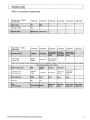
Feature Bank 1 - 3 Chirps
Transmitter Programming
Refer to transmitter programming.
2012 Audiovox Electronics Corporation. All rights reserved.
17
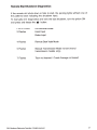
Feature Bank 5 - 7 Chirps
Pin Alternate Output Control
4
Black I Yellow Output
Pulse During
Crank
Ground While
Running
Ignition
NOTE: On this model the Lt Green I Black Output wire can be configured in Bank 3 or Bank 5. Any changes to this feature in Bank 5
will override changes made in Bank 3.
18
ca5553sst rev A
Tach Programming
The unit will not operate unless a tach signal is programmed or the
tachless option is turned ON. If an attempt is made to start the vehicle via the
remote start without first programming tach, the unit will flash the parking lights 7
times indicating tach has not been learned and stored. If the tach rate is not
properly programmed to the specific vehicle, the unit may not realize that the
vehicle is running in certain instances and reengage the starter motor.
The Remote Start unit will learn the tach rate of most vehicle's single coil, multiple coil
packs, or single injector. To learn tach:
1.
2.
3.
Turn the ignition key to the ON position.
Press and release the valet/override button 3 times.
Immediately turn the ignition key OFF.
4.
Press and hold the valet/override button, then start the vehicle using
the key.
5.
When the unit senses the tach signal, the parking lights will begin to
flash.
6.
Allow the vehicle to settle to a normal idle speed.
7.
Release the valet/program push-button switch. 1 long chirp and the
parking lights will turn on for 2 seconds, indicating that the learned
tach signal is stored and the unit has exited tach learn mode.
NOTE: If the unit fails to learn tach rate due to an improper tach connection or a
poor tach source, the parking lights will not flash. To correct this situation, locate
and connect the PURPLE/WHITE wire to the proper tach signal, and then repeat
the tach learn routine.
Smart Tachless Mode
Smart Tachless Mode is available only if a tach signal has never been learned to
the system and when activated will automatically change the Tach Mode feature
in option programming to Tachless without the need to enter the feature
programming mode.
1.
Activate the remote start. The parking lights should begin flashing 7
times indicating no tach signal has been learned.
2.
Within the 7 flash time period, press and hold the () button.
The system will chirp 1 time indicating the system is now in tachless
mode.
3.
2012 Audiovox Electronics Corporation. All rights reserved.
19
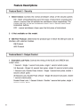
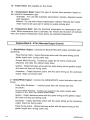
Feature Descriptions
Feature Bank 2 - Security
1 - Silent Choice: Controls the normal arm/disarm chirps of the security system.
ON - Silent arming/disarming upon first press of lock/unlock, pressing lock/
unlock a second time will activate the arm/disarm chirps respectively. The
system will only sound the arm/disarm chirps upon a second press of the
lock/unlock buttons.
OFF - normal arm/disarm chirps upon the first press of lock/unlock.
2 - 8 Not available on this model.
9 - OBI Port Protocol: Determines the protocol type in which the OBI port uses to
interface with external modules.
OBI Protocol
ADS Protocol
Feature Bank 3- Output Control
1 - Extended Lock Pulse: Controls the timing of the BLUE and GREEN lock
output wires.
1 Second - Single 1 second lock pulse, single 1 second unlock pulse.
3.5 Seconds - Single 3.5 second lock pulse, single 3.5 second unlock pulse.
1 Second Lock, Double Pulse Unlock- Single 1 second lock pulse, double 1
second unlock pulse.
30 Second Lock, Double Pulse Unlock- Single 30 second lock pulse, double
1 second unlock pulse.
Double Pulse Lock, 1 Second Unlock - Double 1 second lock pulse, single 1
second unlock pulse.
20
ca5553sst rev A
2- Factory Disarm: Controls the timing of the LT. GREEN/BLACK factory disarm
output.
Factory Disarm - Single 1 second pulse with unlock and remote start
activation.
2nd Unlock - Same output as unlock with 2nd press of unlock. .
Start Status - Single 1 second pulse with unlock and continuous ( - ) output
during the remote start cycle.
NOTE: On this model the Lt Green I Black Output wire can be configured in Bank
3 or Bank 5. Any changes to this feature in Bank 5 will override changes made in
Bank 3.
3 - Ignition Controlled Locks: Control of door locks when the ignition is cycled
ON or OFF.
OFF- Door locks not activated by ignition.
Lock and Unlock - Doors lock when ignition is turned on and unlock when
ignition is turned off.
Lock Only- Doors lock when ignition is turned on only.
Unlock Only Doors unlock when ignition is turned off only.
4 - Trunk Output Timing - Red/White Output: Controls the output timing/type
of the RED/WHITE output.
1 Second Pulse- 1 second pulse output.
10 Second - Continuous output for 10 seconds.
20 Seconds - Continuous output for 20 seconds.
Latched until IGN ON - Continuous output until the vehicle's ignition is turned
ON.
Latched ON until Button Press - Continuous output until the activation button
is pressed again.
5 - Horn Output Timing: Control the minimum horn pulse time in milli seconds,
some vehicle will require a longer pulse to activate the factory horn.
16mS
1OmS
30mS
40mS
50mS
6 - Real Panic: Controls the panic out when triggered from the transmitter.
ON - Randomized horn honks when panic is triggered.
OFF - Standard pattern horn honks when panic is triggered.
2012 Audiovox Electronics Corporation. All rights reserved.
21
7- AUX 1: Controls the VIOLET/BLACK AUX 1 output activation type and timing.
Push and Hold - Output is continuously active until transmitter button is
released.
Latched - Output stays active until button is pressed again.
Latched until IGN ON -Output stays active until the ignition is turned on.
Dome Light Output - Output used for illuminated entry and is not controlled
by the AUX 1 function of the transmitter.
Defrost Output Single Pulse - Single 1 second pulse after start
Defrost Output Latched 5 Minutes - 5 minute continuous output after
remote start.
Feature Bank 4- Remote Start Control
1 - RF Start Chirp: Turns remote start activation confirmation chirps ON or OFF.
2 - Run Time: Controls the time in minutes that the vehicle will stay running
under control of the remote start until the system times out. The system may also
be shut down at any time by use of the transmitter or system shutdowns.
3- Running Lights: Controls the WHITE parking light output wire during remote
start.
Steady - Parking lights constant during the remote start cycle.
Flashing - Parking lights flash at a slow pace during the remote start cycle.
4 - Tach Mode: Determines how the system monitors the engine running during
remote start.
Tach - Hard wired directly to the tach wire of the vehicle to monitor AC
voltage.
Tachless (Crank AverageNoltage) - Determines crank time by averaging the
last 8 times the vehicle was started with the key and then monitors the
change in voltage after remote start.
Hybrid (Crank Average I No Voltage) - Determines crank time by averaging
the last 8 times the vehicle was started with the key.
OBI Port - Monitors the vehicle's tach rate through an interface module
connected to the OBI port.
22
ca5553sst rev A
5 - Voltage Level: The voltage variance for remote start when set to tachless.
(see tach mode)
HIGH -The variance in battery voltage from before the remote start
is activated to after the engine is running must be greater than 0.5 volts.
LOW- The variance in battery voltage from before the remote start
is activated to after the engine is running may be less than 0.5 volts.
6- Crank Time: Preset output times for the PURPLE starter wire.
1 Second
0.8 Seconds
1.5 Seconds
2 Seconds
4 Seconds
7 - Crank Average I Crank Time: The length of time in which the remote start
will crank the vehicle's starter.
Crank Average - Determines crank time by averaging the last 8 times the
vehicle was started with the key.
Preset Time - Preset starter output time. (see crank time)
8 - Gas I Diesel: Selects engine type and delay time for the starter output wire
during remote start activation.
Gas - Gasoline engine, no delay for the starter output wire.
10 Second Delay - Diesel engine, delays the starter output wire for 10
seconds after the ignition has been powered up by the remote start.
15 Second Delay - Diesel engine, delays the starter output wire for 15
seconds after the ignition has been powered up by the remote start.
20 Second Delay - Diesel engine, delays the starter output wire for 20
seconds after the ignition has been powered up by the remote start.
45 Second Delay - Diesel engine, delays the starter output wire for 45
seconds after the ignition has been powered up by the remote start.
9 - Single I Double Pulse Start: Switches the remote start activation between
a single or double press from the transmitter.
10 - IGN 2 Output: Programmable high current output.
Ignition 2 - Ignition output during remote start.
Accessory - Accessory output during remote start.
Start I Crank - Crank output during remote start.
11 - 2 or 3 Hour Start: Not available on this model.
2012 Audiovox Electronics Corporation. All rights reserved.
23
12 - Turbo Timer: Not available on this model.
13 - Transmission Mode: Select the type of remote start activation based on
the vehicle's transmission type.
Automatic - For use with automatic transmission vehicles. Standard remote
start operation.
Manual - For use with manual transmission vehicles. Remote start ready
mode must be set upon exit of vehicle to enable remote start.
14 - Temperature Start: Sets the threshold temperature for temperature start
mode. When temperature start is activated, the remote start function will activate
when the ambient temperature drops below the selected temperature.
Feature Bank 5-4 Pin Alternate Output Control
1 - Black/Yellow Output : Controls the BLACK/YELLOW output activation type
and timing.
Pulse During Crank - Output becomes active with the same timing as the
starter output wire, during crank only.
Ground While Running - Continuous output for the entire remote start
sequence until after the vehicle shuts down.
Ignition - Output becomes active with the same timing as the ignition output
and does not drop out during crank.
Accessory - Output becomes active with the same timing as the accessory
output, drops out during crank.
2- Green/White Output: Controls the GREEN/WHITE output activation type and
timing.
Pulse After Shutdown - 1 second pulse after the remote start has
shutdow n.
Ground While Running - Continuous output for the entire remote start
sequence until after the vehicle shuts down.
Ignition- Output becomes active with the same timing as the ignition output
and does not drop out during crank.
Accessory - Output becomes active with the same timing as the accessory
output, drops out during crank.
Pulse During Crank - Output becomes active with the same timing as the
starter output wire, during crank only.
24
ca5553sst rev A
4 - Lt Green/Black Output : Controls the LT GREEN/BLACK output activation
type and timing.
Pulse before Start I During Unlock - 1 second pulse when remote start is
activated. Also a 1 second pulse when unlock is pressed.
Ground While Running -Continuous output for the entire remote start
sequence until after the vehicle shuts down.
Ignition -Output becomes active with the same timing as the ignition output
and does not drop out during crank.
Accessory - Output becomes active with the same timing as the accessory
output, drops out during crank.
Pulse During Crank - Output becomes active with the same timing as the
starter output wire, during crank only.
3- Lt Blue Output: Controls the LT BLUE output activation type and timing.
Pulse After Start I During Lock - 1 second pulse after the remote start
sequence and has confirmed the vehicle is running. Also a 1 second pulse
when unlock is pressed.
Ground While Running - Continuous output for the entire remote start
sequence until after the vehicle shuts down.
Ignition- Output becomes active with the same timing as the ignition output
and does not drop out during crank.
Accessory - Output becomes active with the same timing as the accessory
output, drops out during crank.
Pulse During Crank - Output becomes active with the same timing as the
starter output wire, during crank only.
2012 Audiovox Electronics Corporation. All rights reserved.
25
Transmitter Button Functions
1 Way
Press Unlock + Start While Armed
26
ca5553sst rev A
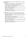
Remote Start Shutdown Diagnostics
If the remote start shuts down or fails to start, the parking lights will flash one of
the patterns below indicating the shutdown input.
To manually enter diagnostics and view the last shutdown, turn the ignition ON
and press and release the 14• button.
LED FLASHES
SHUTDOWN ZONE
3 Flashes
Hood Input
Brake Input
4 Flashes
Remote Start Valet Mode
5 Flashes
Manual Transmission Mode not set (manual
transmission models only)
7 Flashes
Tach not learned I Crank Average not learned
2012 Audiovox Electronics Corporation. All rights reserved.
27
N
(X)
BLUE
GREEN
UNLOCK (-)
LOCK (-)
BLACK/YELLOW
GREEN/WHITE
LT BLUE
LT GREEN/BLACK
PULSE DURING CRANK ( - )
PULSE AFTER SHUTDOWN ( - )
FACTORY ARM I PULSE AFTER START ( - )
FACTORY DISARM I PULSE BEFORE START ( - )
D
BLACK
WHITE/RED
WHITE
E~
n:[ri
~~
~~
IU~
o;:;
0~
ull)
GROUND
PARKING LIGHT INPUT
PARKING LIGHT OUTPUT
GRAY/RED
PURPLE
GREEN
BLACK/WHITE
BROWN/BLACK
RED/WHITE
BLUE/BLACK
PURPLE/WHITE
GRAY
BROWN/RED
VIOLET/BLACK
PARKING BRAKE INPUT ( - )
DOOR INPUT ( + )
DOOR INPUT ( - )
ILLUMINATED ENTRY OUTPUT ( - )
HORN OUTPUT ( - )
TRUNK RELEASE OUTPUT ( - )
START STATUS I ACTIVE OUTPUT ( - )
TACH INPUT
HOOD INPUT ( - )
BRAKE INPUT ( + )
AUX 1 OUTPUT ( - )
OBI PORT
()9
:
)
ANTENNA
LED
VALET
TELEMATIC PORT
C")
~
~
~
m
<
)>
PURPLE
RED
ORANGE
PINK/WHITE
RED/WHITE
PINK
STARTER OUTPUT- MOTOR SIDE ( + )
BATTERY 12V ( +)
ACCESSORY 1 ( + )
IGNITION 2 ( +)
BATTERY 12V ( +)
IGNITION 1 ( + )
2012 Audiovox Electronics Corporation. All rights reserved.
29
30
ca5553sst rev A
2012 Audiovox Electronics Corporation. All rights reserved.
31
Audiovox Electronics Corporation.
Customer Service 1-800-421-3209
WWW.CODE-ALARM.COM
FCC COMPL IANCE
This device complies with Part 15 of the FCC rules and with RSS-21 0 of
Industry Canada. Operation is subject to the following two conditions:
1. This device may not cause harmful interference, and
2. This device must accept any interference received, including any interference
that may cause undesired operation.
Warnin g!
Changes or modifications not expressly approved by the party responsible for
compliance could void the user's authority to operate the equipment.
32
R41 0-192-540
ca5553sst rev A
cccc:~L'.I~m
Deluxe Vehicle Remote Start System
with 900Mhz 2 Way Confirming LCD
Remote Control
IMPORTANT NOTE: The operation of the Security and Convenience System as described in this manual is
applicable to most vehicles. However, due to the configuration of some vehicles, some functions AND/OR
SAFETY PRECAUTIONS may not apply. Please see your installing dealer for more information.
2012 Audiovox Electronics Corporation. All rights reserved.
4280479
Table of Contents
Using Your Remote Control ............................................................... 3
Using the Keyless Entry ................................................................... 3
Two Stage Door Unlock (optional) ................................................... 3
Activating Trunk Release (optional) ................................................ 3
Activating AUX 1 (optional) .............................................................. 3
Using the Progressive Car Finder Feature ...................................... 3
Using the Personal Protection Alarm ............................................... 3
Programmed Transmitter Notification .............................................. 4
Valet Mode ........................................................................................ 4
Eliminating Lock I Unlock Notification Chirps ................................... 4
Using Your Remote Starter ................................................................ 5
Remote Start Ready Mode ................................................................ 5
Cancelling Remote Start Ready Mode ............................................. 5
Remote Starting Your Vehicle .......................................................... 6
Remote Start Shutdown ................................................................... 6
Entering Your Vehicle while it is Running via Remote Start ........... 6
Preheating or Precooling the Vehicle's Interior ............................... 6
User Programmable Run Time I Run Time Extension ...................... 7
Using the Quick Stop Feature .......................................................... 7
Operating the Daily Start Timer ........................................................ 7
Temperature Start Mode ................................................................... 8
Remote Start Safety Features ......................................................... 8
Additional 2-Way LCD Remote Control Functions ........................ 9
LCD Remote Control ICON's ............................................................ 11
Transmitter Button Functions ......................................................... 12
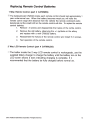
Replacing Remote Control Batteries ............................................. 13
Warranty Information ......................................................................... 14
2
ca5553sst rev A
Using
y~,ur
Remote Control
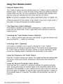
Using the Keyless Entry
The @ button is used to lock the vehicle's doors, the riJ button is used to unlock the
vehicle's doors. To lock or unlock the doors simply press and release the desired
function button one time. For your convenience, the parking lights will flash once
when the doors are unlocked and twice when the door are locked.
NOTE: The system is equipped with a feature called Silent Choice. If enabled, the
system requires a second press of the @ or riJ button to activate an audible locking/
unlocking response from the vehicle. If your system is set up for 2 step unlock, a
third press of unlock will activate the audible response.
Two Stage Door Unlock (Optional)
If this feature is enabled on your system, pressing the ciJ button one time will
unlock only the driver's door. Press ciJ again within three seconds to unlock the
remaining doors.
Activating the Trunk Release Feature (Optional)
The ciJ button is used to open the trunk of the vehicle. To open the vehicle's trunk
press and hold the ciJ button for 3 seconds.
Activating AUX 1 (Optional)
If this feature is enabled on your system, pressing the @ and ciJ buttons
simultaneously will activate an optional feature. This feature can be programmed
for a wide range of functions like power window or sunroof automation, please
consult your installing dealer to determine the functionality of your system.
Using the Progressive Car Finder Feature
Press the cJ>)) button to locate your vehicle. The system will flash the parking lights
and sound 5 times at low volume, increasing in volume each time the button is
pressed.
Using the Personal Protection Alarm (Panic)
Press and hold the cJ>)) button for 3 seconds to activate the personal protection
alarm. During panic mode, the normal function of the transmitter buttons will be
suspended. The transmitter's @ and (iJ buttons can be used to lock and unlock the
door (if the option is installed). To stop the alarm, press and hold the cJ>)) button on
the transmitter again for 3 seconds. The system will automatically stop after 30
seconds.
2012 Audiovox Electronics Corporation. All rights reserved.
3
Programmed Transmitter Notification
As a security precaution each time the vehicle's ignition is turn on the status LED
light with flash the number of transmitters programmed into the system. This helps
to identify unauthorized transmitters from accessing your vehicle. If you believe an
unauthorized transmitter has been programmed to your system, contact your
installing dealer for assistance.
Valet Mode
Valet Mode is used to disable the system from remote starting. To enter or exit
valet mode simply follow the 4 steps outlined below:
1.
Turn the vehicle's ignition ON.
2.
Push and hold the programming/valet button.
3.
The LED will turn on solid when valet mode is active
4.
Release the programming/valet button.
Eliminating Lock I Unlock Notification Chirps
System lock and unlock notification chirps can be toggled ON or OFF without
entering the programming feature banks.
4
1.
Turn the ignition ON then OFF.
2.
Press and release the valet/programming button 3 times. The system
will respond with 1 chirp for ON or 2 chirps for OFF.
ca5553sst rev A
Using Your Remote Starter
Remote Start Ready Mode must be enabled if your vehicle is equipped
with a manual transmission.
Remote Start Ready Mode - Manual Transmission Vehicles Only
To activate the remote start function, the system must first be in Remote Start
Ready Mode. Follow the steps below to enter remote start ready mode.
1.
While the engine is running by the ignition key;
a.
Set the parking brake
b.
Place the transmission in neutral.
2.
With your foot off the brake pedal, press and release the 0 button 2
times within 2 seconds. The LED will flash 3 times and the parking
lights will turn on to confirm the system has entered quick stop mode.
3.
Remove the keys from the ignition, the vehicle will remain running in
quick stop mode.
4.
Exit the vehicle and close all vehicle doors.
5.
Within 1 minute of step 1, press the ~ button to lock the vehicle's
doors. The vehicle will shutdown and sound 2 short chirps then 1 long
chirp to confirm ready mode is set.
Cancelling Remote Start Ready Mode
The system will exit remote start ready mode if any of the following occur:
Open any door
Open the hood or trunk (if connected)
Press the brake
Release the parking brake
Turn the ignition ON
2012 Audiovox Electronics Corporation. All rights reserved.
5
Remote Starting Your Vehicle
To activate the remote start function, press and release the 0 button 2 times within
2 seconds. The system will sound, the parking lights will flash 1 time and the
system will check the vehicle to ensure it is safe to start. If all safety parameters
are correct, the vehicle will start within 5 seconds. The vehicle's parking lights
will turn on (or flash depending on system settings) as a visual indication that the
vehicle has started and is running.
If your vehicle stalls or does not start, the system will pause 5 seconds, then try 2
more times to start the vehicle (a total of 3 attempts). The system will pause 5
seconds between each start attempt. If the vehicle does not start after the 3rd
attempt, the system will abort the remote vehicle start process.
Note: Do not leave children or animals unattended in the vehicle when using the
remote start feature.
Note: Manual transmission vehicles - Remote Start Ready Mode must be set.
Remote Start Shutdown
Press and hold the 0 button for 3 seconds to turn the vehicle off.
Entering the Vehicle while it is Running via Remote Vehicle Start
1.
Unlock the vehicle's doors.
2.
Enter the vehicle. DO NOT PRESS THE BRAKE PEDAL!
3.
Insert the key into the ignition switch and turn to the ON or RUN
position.
4.
Press the brake pedal. The remote vehicle starter will disengage and
the vehicle will operate normally.
Preheating or Precooling the Vehicle's interior
Before exiting the vehicle, set the temperature controls to the desired setting and
operation. After the system starts the vehicle, the heater or air conditioner will
activate and heat or cool the vehicle's interior to your setting.
6
ca5553sst rev A
User Programmable Run Time I Run Time Extension
The system has the ability to allow the user to extend the time the vehicle will be
running under control of the remote start. This will only extend the run time back to
the current run time setting during the current remote start cycle. If your system is
set to run 15 minutes and the time remaining is 4 minutes, extending the run time
will reset the countdown timer to 15 minutes and your vehicle will continue to run
for another 15 minutes. Follow the steps below to extend the vehicle's run time.
1.
The remote start must already be active.
2.
Press and release the 0 button 4 times.
3.
The system will chirp 1 time and flash the parking lights 4 times to
confirm that the run time has been reset.
Using the "Quick-stop" Feature - Automatic Transmission Vehicles
If you want to make a short stop and keep your vehicle running (to keep the
interior warm or cool), the quick-stop feature allows you to do this while keeping
your vehicle secure and your keys with you.
To engage quick stop:
1.
Stop the vehicle and place the transmission in PARK.
2.
With your foot off the brake pedal, press and release the 0 button 2
times within 2 seconds. The LED will flash 3 times to confirm quick
stop is entered.
3.
Remove the keys from the ignition and exit the vehicle. Press the
@ button to lock the vehicle's doors if desired.
Note: Do not leave children or animals unattended in the vehicle when using the
quick-stop feature.
Operating the Daily Start Timer
The system has the ability to start your vehicle based on a 24-hour countdown
timer. This feature requires a two-part activation sequence. From the remote,
pressing both the @ & 0 buttons together will activate the 24 hour countdown
timer (the vehicle will start 24 hours from this time). Next, When you are finished
operating the vehicle for the day, perform the following steps to complete the
process.
1.
Turn the ignition ON/OFF (vehicle must be disarmed).
2.
Within 10 seconds, while pressing the brake, press and release the 0
button twice.
3.
The vehicle will emit 2 chirps and flash the parking lights 4 times.
2012 Audiovox Electronics Corporation. All rights reserved.
7
Temperature Start Mode
The system has the ability to start the vehicle if the temperature drops below a
preset temperature threshold. Once activated, the system will only start the
vehicle one time based on the temperature setting and will be cancelled if the
vehicle is started with the key or remote started by the transmitter. Temperature is
read from the module, located below the dashboard in most instances, and the
vehicle's interior temperature may vary from the ambient temperature.
1.
The vehicle must be armed.
2.
Press and release both the
3.
The vehicle will emit 1 chirp and flash the parking lights 1 time.
riJ
& 0 buttons together.
Note: This feature is defaulted OFF and must be set in option programming.
Remote Start Safety Features
For safety and security reasons, the system will shutdown or prevent the remote
vehicle starter from activating if any of the following occur:
8
1.
The vehicle hood is open.
2.
The brake pedal is pressed prior to turning the ignition key to the ON
position.
3.
The engine is over-revved (tach checking only).
4.
Valet mode is active.
ca5553sst rev A
Additional 2-Way LCD Remote Control Functions
Check Vehicle Status
Press and release [f 2 times then press @ within 3 seconds, the transmitter will
display the current status of the vehicle.
Display Illumination
Press and hold the [p button for 1 second. The display will illuminate for 5
seconds.
Melody I Vibration Mode
To have the remote control vibrate, play a melody tone or both each time it receives
a response from the vehicle press and release [f then press and hold ciJ for 2
seconds.
Button Beeps
To toggle button beeps on or off press and release [f then press and hold 0 for 2
seconds.
Battery Save Mode
While in POWER SAVE MODE the 2-way LCD transmitter will NOT look for any
incoming signals from the main unit until a button is pressed. The LCD screen will
display SAVE to indicate that power save mode is ON. To enter power save mode
press and hold [p for 5 seconds.
Clear Flashing Icons and Melody Sound
Press the [f button 3 times within 3 seconds. This will clear the melody sound and
flashing icons on the LCD screen.
Button Lock
Press and release [f then press hold the @ for 2 seconds to toggle the button lock
on or off. When the button lock is active, the remote control will beep/vibrate 2
times when a button is pressed indicating it is locked.
Illumination
Press and release [p 2 times then press and hold @ for 2 seconds to toggle
illumination on or off. When on, the display will illuminate when it receives or
sends a command.
2012 Audiovox Electronics Corporation. All rights reserved.
9
2 Car Mode
To control a second security system enter 2 car mode by pressing ~ then press @
and riJ together for 3 seconds. When the !Jil icon appears on the transmitter's LCD
screen it will control the second security system. Use the same method to exit 2
car mode and resume control of the original vehicle's security system.
NOTE: A second security system must be installed and the LCD transmitter must be
learned to it before this feature will operate the additional system.
Parking Meter Countdown
The parking meter countdown timer has 6 preset times, to access the preset times
and begin countdown press and release [? then press and hold c:J>}) for 2 seconds,
each additional press of c:J>}) will increase the countdown time.
Adjusting the Clock and Timer Settings
The clock, alarm clock and programmable countdown timer are accessed through
the Function Menu. Press and hold [?for 3 seconds to access the function menu,
once you have accessed the feature menu press and release [?to scroll through
each feature and follow the steps below to adjust the settings for each. Press and
hold [? for 2 seconds to exit the menu.
10
Clock Hour
Press
c:J>})
to increase or 0 to decrease
Clock Minute
Press
c:J>})
to increase or 0 to decrease
Alarm Clock Hour
Press
c:J>})
to increase or 0 to decrease
Alarm Clock Minute
Press
c:J>})
to increase or 0 to decrease
Alarm Clock ON I OFF
Press
c:J>})
to turn ON or 0 to turn OFF
Countdown Timer Hour
Press
c:J>})
to increase or 0 to decrease
Countdown Timer Minute
Press
c:J>})
to increase or 0 to decrease
Countdown Timer ON I OFF
Press
c:J>})
to turn ON or 0 to turn OFF
ca5553sst rev A
LCD· Remote Control ICON's
~
LOCK
~
UNLOCK
~
TRUNK RELEASE
~~
VALET MODE
~«)1»~
TRANSMITTING
~«a~
PANIC
6)
ENGINE RUNNING
<looo~
BATTERY INDICATOR
~
TIMER/TEMP
START MODES
~~
ii
VIBRATE/SILENT MODE
Iill
2 CAR MODE
2012 Audiovox Electronics Corporation. All rights reserved.
:88:88
~ffi\~~
X
TIME DISPLAY
BATTERY SAVE MODE
TIME COUNT DOWN
t
MELODY MODE
~
ALARM CLOCK
11
Transmitter Button Functions
Press Unlock + Start While Armed
12
ca5553sst rev A
Replacing Remote Control Batteries
1-Way Remote Control (part # CATXMSS)
The battery (model CR2032) inside each remote control should last approximately 1
year under normal use. When the battery becomes weak you will notice the
remote control range (the distance from the vehicle the remote control will work)
deteriorate and the small LED on the remote control will dim. To replace the remote
control batteries:
1.
Remove 3 screws and disassemble the halves of the remote control.
2.
Remove the old battery, observing the +1- symbols on the battery
and replace with a new CR2032 battery.
3.
Reassemble the halves of the remote control and install the 3 screws.
4.
Test operation of the remote control.
2 Way LCD Remote Control (part # CATXMLSS)
The battery inside the 2 way LCD remote control is rechargeable, use the
supplied battery charger to charge the battery until the battery icon on the
LCD screen shows 3 bars indicating charging is complete. It is
recommended that the battery be fully charged before normal use.
2012 Audiovox Electronics Corporation. All rights reserved.
13
CCCC~LI.I~m
Code Systems, Inc. Limited Lifetime Warranty
Code Systems Inc. ("CODE") warrants to the ORIGINAL PURCHASER of this CODE vehicle
security product (the "Product"), purchased from an authorized CODE dealer, that (except as
provided below) should this Product under normal use and conditions, be proven defective in
material or workmanship DURING THE LIFETIME OF THE VEHICLE IN WHICH IT WAS ORIGINALLY INSTALLED, such defect(s) will be repaired or replaced (at CODE's option) without charge
for parts directly related to repairs of the defect(s).
Switches, indicator lights, and transmitter cases are similarly warranted to the original purchaser
for a period of one (1) year from the date of purchase of the Product.
CODE accessories, sold separately, are covered by the applicable warranty accompanying the
accessory.
This warranty is non-transferable, non-assignable and is voided when: (1) the Product is removed
from the vehicle in which it was originally installed; or (2) the vehicle in which the Product was
originally installed is transferred to another party.
This warranty does not apply to any product damaged by accident, physical or electrical abuse,
improper installation, alteration, or use contrary to its intended function, fire, flood, or other
natural acts.
In order for the Product to be repaired or replaced under the terms of this warranty, the defective
Product must be returned to an authorized CODE dealer and accompanied by a copy of the retail
sales receipt. The date of purchase and year, make and model of the vehicle in which the Product
was originally installed must be clearly indicated on the sales receipt.
This warranty is exclusive and CODE MAKES NO OTHER WARRANTIES EXPRESSED OR
IMPLIED. ANY IMPLIED WARRANTIES, INCLUDING ANY IMPLIED WARRANTY OF MERCHANTABILITY AND FITNESS FOR A PARTICULAR PURPOSE, SHALL BE LIMITED TO THE
DURATION OF THIS WRITTEN WARRANTY. IN NO CASE SHALL CODE BE LIABLE FOR ANY
CONSEQUENTIAL OR INCIDENTAL DAMAGES FOR BREACH OF THIS OR ANY OTHER
WARRANTY, EXPRESS OR IMPLIED, WHATSOEVER.
CODE does not warrant that the Product cannot be compromised or circumvented. THE EXTENT
OF CODE'S LIABILITY UNDER THIS WARRANTY IS LIMITED TO THE REPAIR OR REPLACEMENT PROVIDED ABOVE AND, IN NO EVENT SHALL CODE'S LIABILITY EXCEED THE PURCHASE PRICE PAID BY THE ORIGINAL PURCHASER OF THE PRODUCT WITHOUT INSTALLATION LABOR.
Some states do not allow the exclusion or limitation of incidental or consequential damages, so the
above limitation may not apply to you. This warranty gives you specific legal rights and you may
also have other rights which vary from state to state
14
ca5553sst rev A
This product is covered by one or more of the following U.S. Patents; Other Patents pending.
0407,034,0580,160,5,1 32.660, 5,157,375, 5,193,141, 5,245,694. 5,315,285, 5,334,969
5,349,931, 5,357 ,560, 5,381 '128, 5~412,371, 5,467,070, 5,469.141 t 5,469, 151, 5,506.568
5,532,670. 5,534,845, 5.563,576, 5,563,600. 5,572,185. 5,602,535, 5,614,883, 5,617,819
5,646,591, 5,650,774, 5,656,868, 5,673,017, 5,656,997, 5,712,638, 5,783,988. 5,783,989
5,798,711. 5,805.056, 5,819,568, 5,828,316, 5,838,255, 5.850, 173. 5,850, 174, 5,855,050
5,872,519, 5,898,391 5,900,806,. 5,905,4311 5,907, 195, 5,914,667, 5,945,936, 5,952,933
5,990,786. 6,028,732, 6,028,505, 6,040,636, 6,043,734. 6,087,996, 6,093,979, 6,140,914
6, 184,779, 6,218,740, 6,259, 169, 6,285,296, 6,288,635, 6,317,034, 6,452,483, 6,452,484
6,462,648, 6,573,838, 6,697,719, 6,700,479, 6,781,507. 6,828,901, 6,982.631, 7,030,739
7,069, 127, 7.095,314, 7, 102,515, 7.135,962, 7,142,097, 7,191,053, 7,243,007, 7,248,150
7,332,998, 7,443,285, 7,463, 135, 7,483,783, 7,519,400, 7,532,959, 7,616,099, 7,646,285
7.653,463, 7,962;260
t
2012 Audiovox Electronics Corporation. All rights reserved.
15
Audiovox Electronics Corporation.
Custo mer Service 1-800-421-3209
WWW. CODE -ALAR M .COM
FCC COMPL IANCE
This device complies with Part 15 of the FCC rules and with RSS-21 0 of
Industry Canada. Operation is subject to the following two conditions:
1. This device may not cause harmful interference, and
2. This device must accept any interference received, including any interference
that may cause undesired operation.
Warnin g!
Changes or modifications not expressly approved by the party responsible for
compliance could void the user's authority to operate the equipment.
16
R41 0-192-550
ca5553sst rev A
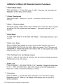
WARNING
THIS VEHICLE IS EQUIPPED WITH A REMOTE
CONTROLLED CAR STARTER
BEFORE SERVICING THIS VEHICLE, REMOVE THE MAIN
POWER FUSE (RED WIRE) TO THE CAR STARTER OR
DISCONNECT THE VEHICLE BATTERY.
LBL0675