1
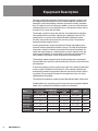
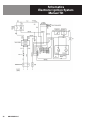
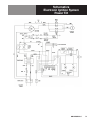
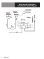
OPERATOR MANUAL
IMPORTANT INFORMATION, KEEP FOR OPERATOR
This manual provides information for:
MODELS BPM-30/40G(S)
& BPP-30/40G Domestic
ECLIPSE™ ERGONOMIC
TILTING BRAISING PAN
· Stainless Steel
· Manual or Power Tilt
· Gas Heated
THIS MANUAL MUST BE RETAINED FOR FUTURE REFERENCE.
READ, UNDERSTAND AND FOLLOW THE INSTRUCTIONS AND
WARNINGS CONTAINED IN THIS MANUAL.
FOR YOUR SAFETY
Do not store or use gasoline or other flammable vapors
and liquids in the vicinity of this or any other appliance.
POST IN A PROMINENT LOCATION
Instructions to be followed in the event user smells
gas. This information shall be obtained by consulting
your local gas supplier. As a minimum, turn off the gas
and call your gas company and your authorized service
agent. Evacuate all personnel from the area.
WARNING
Improper installation, adjustment, alteration, service
or maintenance can cause property damage, injury or
death. Read the installation, operating and maintenance
instructions thoroughly before installing or servicing this
equipment.
NOTIFY CARRIER OF DAMAGE AT ONCE
It is the responsibility of the consignee to inspect the container upon receipt of
same and to determine the possibility of any damage, including concealed damage. Unified Brands suggests that if you are suspicious of damage to make a
notation on the delivery receipt. It will be the responsibility of the consignee to file
a claim with the carrier. We recommend that you do so at once.
Manufacture Service/Questions 888-994-7636.
Information contained in this document is known to be current and accurate at the time
of printing/creation. Unified Brands recommends referencing our product line websites,
unifiedbrands.net, for the most updated product information and specifications.
PART NUMBER 145339, REV. H (01/11)
1055 Mendell Davis Drive
Jackson, MS 39272
888-994-7636, fax 888-864-7636
unifiedbrands.net
IMPORTANT - READ FIRST - IMPORTANT
WARNING: DISCONNECT POWER BEFORE SERVICING. FAILURE TO DISCONNECT COULD RESULT IN ELECTROCUTION
AND DEATH.
CAUTION: UNIT WEIGHS 470 TO 560 LB. (191 TO 255 KG). FOR SAFE HANDLING, INSTALLER SHOULD OBTAIN HELP AS
NEEDED, OR EMPLOY APPROPRIATE MATERIALS HANDLING EQUIPMENT (SUCH AS A FORKLIFT, DOLLY,
OR PALLET JACK) TO REMOVE THE UNIT FROM THE SKID AND MOVE IT TO THE PLACE OF INSTALLATION.
WARNING: INSTALLATION OF THE BRAISING PAN MUST BE DONE BY PERSONNEL QUALIFIED TO WORK WITH GAS
AND ELECTRICITY. IMPROPER INSTALLATION CAN RESULT IN INJURY TO PERSONNEL AND/OR DAMAGE
TO EQUIPMENT.
WARNING: THIS UNIT IS DESIGNED FOR COMMERCIAL USE. NEVER USE HOME OR RESIDENTIAL GRADE GAS
CONNECTIONS. THEY DO NOT MEET COMMERCIAL GAS CODES AND COULD BE HAZARDOUS.
DANGER: ELECTRICALLY GROUND THE UNIT AT THE TERMINAL PROVIDED. FAILURE TO GROUND UNIT COULD
RESULT IN ELECTROCUTION AND DEATH.
WARNING: KEEP THE APPLIANCE AREA FREE AND CLEAR OF COMBUSTIBLE MATERIALS. FAILURE TO DO SO COULD
RESULT IN FIRE OR PROPERTY DAMAGE.
CAUTION: BE SURE ALL OPERATORS READ, UNDERSTAND AND FOLLOW THE OPERATING INSTRUCTIONS,
CAUTIONS AND SAFETY INSTRUCTIONS CONTAINED IN THIS MANUAL.
CAUTION: KEEP FLOORS IN BRAISING PAN WORK AREA CLEAN AND DRY. IF SPILLS OCCUR, CLEAN IMMEDIATELY
TO AVOID THE DANGER OF SLIPS OR FALLS.
WARNING: WHEN TILTING BRAISING PAN FOR PRODUCT TRANSFER:
1) USE CONTAINER DEEP ENOUGH TO CONTAIN AND MINIMIZE PRODUCT SPLASHING.
2) PLACE CONTAINER ON STABLE, FLAT SURFACE, AS CLOSE TO PAN AS POSSIBLE.
3) STAND TO SIDE OF PAN WHILE POURING — NOT DIRECTLY IN POUR PATH OF HOT CONTENTS.
4) RETURN PAN BODY TO LEVEL POSITION AFTER CONTAINER IS FILLED OR TRANSFER IS COMPLETE.
5) DO NOT OVERFILL CONTAINER, AVOIDING DIRECT SKIN CONTACT WITH HOT CONTAINER AND ITS CONTENTS.
WARNING: DO NOT HEAT EMPTY PAN FOR MORE THAN 5 MINUTES AT A SETTING HIGHER THAN 300ºF.
WARNING: IF THE PAN CONTAINS ITEMS IN HOT LIQUIDS SUCH AS SAUCE OR MELTED FAT, THEY CAN SLIDE
FORWARD SUDDENLY DURING TILTING AND CAUSE THE HOT LIQUID TO SPLASH OUT.
WARNING:
AVOID ALL DIRECT CONTACT WITH HOT FOOD PRODUCT OR WATER IN THE PAN. DIRECT CONTACT
COULD RESULT IN SEVERE BURNS.
WARNING: IT IS RECOMMENDED THAT WATER AND SOLUTIONS BE KEPT OUT OF CONTROLS AND BURNERS. DO
NOT USE HIGH PRESSURE SPRAY DIRECTLY ON THE CONTROL CONSOLE, ELECTRICAL CONNECTIONS
AND BURNERS. USE A GARDEN HOSE SPRAY CONNECTED TO CITY WATER SUPPLY.
CAUTION: MOST CLEANERS ARE HARMFUL TO THE SKIN, EYES, MUCOUS MEMBRANES AND CLOTHING.
PRECAUTIONS SHOULD BE TAKEN TO WEAR RUBBER GLOVES, GOGGLES OR FACE SHIELD AND
PROTECTIVE CLOTHING. CAREFULLY READ THE WARNINGS AND FOLLOW THE DIRECTIONS ON THE
LABEL OF THE CLEANER TO BE USED.
WARNING: BEFORE REPLACING ANY PARTS, DISCONNECT THE UNIT FROM THE ELECTRIC POWER SUPPLY AND
CLOSE THE MAIN GAS COCK. ALLOW FIVE MINUTES FOR UNBURNED GAS TO VENT.
CAUTION: USE OF ANY REPLACEMENT PARTS OTHER THAN THOSE SUPPLIED BY AUTHORIZED DISTRIBUTORS CAN
CAUSE INJURY TO THE OPERATOR AND DAMAGE TO THE EQUIPMENT AND WILL VOID ALL WARRANTIES.
IMPORTANT: SERVICE PERFORMED BY OTHER THAN GROEN AUTHORIZED SERVICE AGENT WILL VOID ALL
WARRANTIES.
2
OM-BPM/BPP-G
Table of Contents
Important Operator Warnings .........................................................page 2
References.................................................................................... page 3
Equipment Description............................................................... page 4-5
Inspection and Unpacking ............................................................ page 6
Installation .................................................................................. page 7-8
Initial Start-Up................................................................................ page 8
Operation ................................................................................ page 9-11
Sequence of Operation ........................................................... page 12-13
Cleaning........................................................................................ page 14
Maintenance................................................................................. page 15
Troubleshooting..................................................................... page 16-18
Schematics/Wiring Diagram ................................................ page 30-32
Service Log .......................................................................... page 33-34
References
CANADIAN STANDARDS ASSOCIATION
8501 East Pleasant Valley Road
Cleveland, Ohio 44131
Z83-11 - Gas Foodservice Equipment
Z223.1 - National Fuel Gas Code
AMERICAN NATIONAL STANDARDS INSTITUTE
1403 Broadway
New York, New York 10018
CANADIAN GAS ASSOCIATION
55 Scarsdale Road
Don Mills, Ontario M3B 2 R3
NATIONAL FIRE PROTECTION ASSOCIATION
60 Battery March Park
Quincy, Massachusetts 02269
NFPA/54 - Installation of Gas Appliances & Gas Piping
NFPA/70 - The National Electrical Code
NFPA/96 - Ventilating Hoods
NSF INTERNATIONAL
789 N. Dixboro Road
P.O. Box 130140
Ann Arbor, Michigan 48113-0140
UNDERWRITERS LABORATORIES, INC.
333 Pfingsten Road
Northbrook, Illinois 60062
OM-BPM/BPP-G
3
Equipment Description
Groen gas-heated Eclipse Ergonomic Tilting Braising Pans provide a stainless steel
pan equipped with patented heat transfer fins, burner/combustion chamber, handoperated or electric powered tilting mechanism, thermostatic controls, and hinged
cover. The appliance serves as braising pan, griddle, fry pan, oven, kettle, bainmarie
and food warmer/server, can be adapted for use as a non-pressure steamer and can
be used to stir-fry, reheat and saute foods.
The pan body is made from heavy-duty stainless steel welded into one solid piece,
with a polished interior and exterior. A pouring lip is welded to the front wall. The
cooking surface is a stainless steel clad plate fitted with welded heat transfer
fins which assure uniform heat transfer over the entire surface. The gas burner/
combustion chamber supplies the heat.
An easily operated worm and gear mechanism tilts the pan and provides precise
control for pouring or dumping the contents of the pan. This hand-wheel controlled
mechanism is located in a stainless steel console to the right of the pan body. For
models with electric power tilt, a switch operates an electric motor that starts and
stops the pan tilt smoothly. To assist cleaning, the pan body can be tilted past the
vertical position. When the pan is tilted, the burners shut off automatically.
The thermostat provides automatic control of cooking temperature. Operating the
thermostat dial on the front of the control console turns the heat on or off and sets the
pan temperature.
A vented, heavy gauge, one-piece, stainless steel cover with a condensate drip shield
on the rear edge is standard on the Braising Pan. A fully enclosed, torsion bar type
counterbalance provides easy operation to open the cover and to maintain it open at
any position. The cover opens to the back and is hinged to the frame, so it moves
independently of the pan body.
The braising pan is mounted on an open-leg frame fabricated from tubular stainless steel.
Standard models have an ignition system that uses electronic spark ignition. Optional
models have a standing flame pilot light that ignites the main burner.
Model
4
OM-BPM/BPP-G
PAN DIMENSIONS
Ignition
Tilt
10" (25 mm)
Elec. Spark
Manual
28-1/4" (718 mm)
10" (25 mm)
Elec. Spark
Power
26-1/4" (667 mm)
28-1/4" (718 mm)
10" (25 mm)
Standing Pilot
Manual
BPM-40G
35-3/4" (908 mm)
28-1/4" (718 mm)
10" (25 mm)
Elec. Spark
Manual
BPP-40G
35-3/4" (908 mm)
28-1/4" (718 mm)
10" (25 mm)
Elec. Spark
Power
BPM-40GS
35-3/4" (908 mm)
28-1/4" (718 mm)
10" (25 mm)
Standing Pilot
Manual
Left to Right
Front to Rear
Depth
BPM-30G
26-1/4" (667 mm)
28-1/4" (718 mm)
BPP-30G
26-1/4" (667 mm)
BPM-30GS
Equipment Description
Optional Tangent Draw-off
Optional equipment available with these models are:
1. Fill faucet with swing spout. (Left or right mounted) - specify single or double
pantry
2. Fill faucet with 48” or 60” spray hose assembly (left or right mounted) - specify
single or double pantry
3. Caster mounting kit
4. Flanged Feet
5. Fold-down work tray (pan support) mounted onright side
6. 2” Tangent draw-off (Factory-installed must be indicated on initial order)
7. Steamer Insert set
8. Steamer Pan Carrier
9. Quick gas disconnect with restraining cable
10. Pouring Lip Strainer
11. Strainer for 2” TDO valve
PERFORMANCE DATA
Model
Firing Rate
BPM-30G
BPM-30GS
104,000 BTU/hr
BPP-30GS
BPM-40G
BPM-40GS
144,000 BTU/hr
BPP-40G
OM-BPM/BPP-G
5
Inspection & Unpacking
CAUTION
SHIPPING STRAPS ARE UNDER TENSION
AND CAN SNAP BACK WHEN CUT.
The unit will arrive completely assembled, wrapped in protective plastic on a heavy skid,
in a heavy cardboard carton. Immediately upon receipt, inspect the carton for damage.
Report any apparent shipping damage or an incorrect shipment to the delivery agent.
CAUTION
UNIT WEIGHS 420 TO 560 LB (190 TO 255
KG). FOR SAFE HANDLING, INSTALLER
SHOULD OBTAIN HELP AS NEEDED, OR
EMPLOY APPROPRIATE MATERIALS
HANDLING EQUIPMENT (SUCH AS A
FORKLIFT, DOLLY, OR PALLET JACK) TO
REMOVE THE UNIT FROM THE SKID AND
MOVE IT TO THE PLACE OF INSTALLATION.
When installation is to begin, get someone to assist in removing the carton. Lift it straight
up and away from the unit. Do not simply raise it and push backwards - it will break
the cover assembly vent handle. Write down the model number, serial number, and
installation date of your unit, and keep this information for future reference. Space for
these entries is provided at the top of the Service Log in this manual.
The unit is strapped to a skid, and shipped in
a heavy cardboard carton. (Shown is a model
BPM-40G with optional right side mounted,
double pantry faucet assembly.)
6
OM-BPM/BPP-G
Cut the straps holding the unit on the skid, and lift the unit straight up off the skid.
Installation
CAUTION
INSTALLER MUST VERIFY THAT THE
INSTALLATION COMPLIES WITH THE
APPLICABLE LOCAL CODES AND
REGULATIONS. THE UNIT MUST BE
INSTALLED BY A LICENSED PLUMBER OR
GAS FITTER WHEN INSTALLED WITHIN THE
COMMONWEALTH OF MASSACHUSETTS.
Install the braising pan in a well ventilated room for efficient performance. Remove
any items which might obstruct or restrict the flow of air for combustion and
ventilation. Clear all combustible material from the area directly around the unit.
1.
Minimum
Clearance
WARNING
INSTALLATION OF THE BRAISING PAN
MUST BE DONE BY PERSONNEL QUALIFIED
TO WORK WITH GAS AND ELECTRICITY.
IMPROPER INSTALLATION CAN RESULT IN
INJURY TO PERSONNEL AND/OR DAMAGE
TO EQUIPMENT.
WARNING
THIS UNIT IS FOR COMMERCIAL USE.
NEVER USE HOME OR RESIDENTIAL GRADE
GAS CONNECTIONS. THEY DO NOT MEET
GAS CODES AND COULD BE HAZARDOUS.
WARNING
ELECTRICALLY GROUND THE UNIT AT
THE TERMINAL PROVIDED. FAILURE
TO GROUND UNIT COULD RESULT IN
ELECTROCUTION AND DEATH.
Electronic spark ignition
Installation on combustible floors is allowed. Ensure minimum clearance to
combustible and noncombustible construction.
Recommended Clearance
Left Side
0”
2” for service
6” when faucet is installed on left side
Right Side
0”
12-16” for service
6” when faucet is installed on right side
Rear
3”
12” for service
2.
Install the unit under a vent hood.
3.
Level the unit by adjusting the bullet feet or floor flanges on the legs. Be sure
the tilting mechanism has been turned all the way to the horizontal position.
Check levelness with a spirit level set on the bottom of the pan body. Anchor the
rear legs securely to the floor if floor flanges are ordered or required.
4.
Complete piping to the gas service with 3/4” inch IPS pipe or approved
equivalent.
5.
For unit on casters, the installation shall be made with a connector that complies
with the standard for Connectors for Movable Gas Appliances, ANSI Z21.69 - CSA
6.16. Restrain movement of the unit by attaching a cable or chain to the eyelet
provided at the back of the frame and anchor the cable or chain to the wall or
floor. Make the length and location of the cable such that the unit cannot pull on
the gas connection while the cable is connected or quick-disconnect.
6.
The gas connection for a unit on casters must be made with a quick-disconnect
device that complies with ANSI Z21.41 - CSA 6.9.
7.
For electronic spark ignition, provide 115VAC, 60 HZ, 1 phase, 5 AMP electrical
service to the field wiring control box at the rear of the electrical console. AN
ELECTRICAL GROUND IS REQUIRED. The unit must be electrically ground in
accordance with local codes, or in the absence of local codes, with the National
Electrical Code, ANSI/NFPA 70, or the Canadian Electrical Code, CSA C22.2, as
applicable.
8.
Installation must conform with local codes or with the American National
Standard Z223, latest edition, National Fuel Gas Code. The pan should be
installed in an adequately ventilated room with a provision for adequate air
supply to the unit. The best ventilation will use a vent hood and exhaust fan. DO
NOT obstruct the flue or vent duct after installation. In Canada, installation must
conform to CAN/CGA B149 Installation Codes for Gas Appliances and Equipment
and/or local codes.
OM-BPM/BPP-G
7
Installation
9. Adequate space for proper service and operation is required. DO NOT block any
air intake spacings to the combustion chamber or obstruct air flow.
10. After the pan has been connected to the gas supply, check all gas joints for
leaks. A soap solution or other suitable leak detector should be used. Do not use
flame to check for leaks.
11. PRESSURE TEST WARNING
a. Test pressure exceeding 0.5 PSIG (3.45kPa). During pressure testing
of the gas supply piping system at pressures exceeding 0.5 PSIG , the
braising pan and its individual shutoff valve must be disconnected from the
gas supply piping system.
b. Test pressure equal to or less than 0.5 PSIG (3.45kPa). During pressure
testing of the gas supply piping system at pressures equal to or less than
0.5 PSIG , the braising pan must be isolated from the gas supply piping
system by closing its individual manual shutoff valve.
Initial Start-Up
WARNING
WATER IS EXTREMELY HOT AND CAN CAUSE
SEVERE BURNS. AVOID CONTACT WITH HOT
WATER WHEN EMPTYING UNIT.
Now that your braising pan has been installed, you should test it to ensure that the
unit is operating correctly.
1. Remove literature and packing materials from the interior and exterior of the
unit.
2. Put enough water into the pan to cover the bottom to a depth of 1/4 to 1/2 inch
(6 to 13 mm).. With the pan body in the horizontal position, note how the water
lies in the pan, to confirm that the pan was leveled properly during installation.
3. Following “To Start Pan” instructions for your pan model, begin heating the water
at a thermostat setting of 235°F. At this setting, heating should continue until the
water boils.
4. To shut down the unit, turn the thermostat dial to “OFF”.
5. Turn the tilting handwheel clockwise to pour out the water and to confirm that
the pan body can be tilted smoothly from horizontal to vertical. For power tilt
models, push the UP/DOWN switch to confirm operation of tilting system.
If the unit functions as described above, it is ready for use. If it does not, contact your
local Authorized Service Agency.
8
OM-BPM/BPP-G
Operation
WARNING
KEEP THE AREA AROUND BRAISING PAN
FREE AND CLEAR OF COMBUSTIBLE
MATERIALS.
CAUTION
KEEP FLOORS IN BRAISING PAN WORK
AREA CLEAN AND DRY. IF SPILLS OCCUR,
CLEAN IMMEDIATELY TO AVOID THE
DANGER OF SLIPS OR FALLS.
CAUTION
REPLACE THE HOLE PLUG BEFORE
CLEANING OTHERWISE WATER COULD
ENTER THE ELECTRICAL CONTROL BOX
AND DAMAGE THE PARTS.
A. Controls
Operator controls for the braising pans are:
1. Power ON Switch and Power ON indicator
2. The thermostat dial, located on the control console to the right rear of the
pan body. This dial is used to turn the thermostat on or off and to set the
thermostat for pan temperatures between 175° and 425°F.
3. HEATing indicator light located on the control panel, lights when the
burners have ignited.
4. The main supply gas valve, installed on the gas line to the unit.
5. For units with standing pilot flame, the gas control valve is on the
Combination Gas Control, which is located under the pan on the gas line to
the burner manifold. This valve has settings of “OFF”, “PILOT”, or “ON” for
the Combination Control.
6. For power tilt units a switch is located on the control panel. It is used to
raise and lower the pan body.
B. Operating Procedure
1. To Tilt Pan Body
Tilting pan body
a. Manual Tilt Model Turn the tilting handwheel clockwise to tilt the pan body, or
counterclockwise to return the pan body to horizontal. 23 complete
turns of the handwheel will tilt the body 90 degrees to vertical.
Gas valve “On”
Gas valve “Off”
b. Power Tilt Model 1. Press the power tilt switch marked “up” to raise the pan or
“down” to lower the pan.
2. The spring loaded switch will return to the OFF (middle) position
when you release it.
3. If the power tilt mechanism stops working (see the
Troubleshooting section) and you must raise or lower the pan
body without delay, you can tilt the body by hand. Remove the
small plug on top of the control box and fit the provided tool
into the hole. Turn the tool clockwise to lower it. It may take
several minutes to move the pan to the desired position, but the
operation can be speeded up by substituting a reversible drill
with a 1/4” hexagonal driver bit in place of the tool.
2. For Standard Models with Electronic Ignition
a. To Start Pan (See Panel Overlay) 1. Set the Power Switch to “OFF.”
2. Set the thermostat to “OFF.”
3. Open the main supply gas valve (handle parallel to the gas pipe).
4. Set Power Switch to “ON.”
5. Rotate the thermostat dial until the Heat Light comes on. (It
lights when the main burner is on).
OM-BPM/BPP-G
9
Operation
CAUTION
DO NOT HEAT AN EMPTY PAN FOR
MORE THAN FIVE MINUTES AT A
SETTING HIGHER THAN 300°F.
DAMAGE TO THE PAN COULD RESULT.
CAUTION
KEEP FLOORS IN BRAISING PAN WORK
AREA CLEAN AND DRY. IF SPILLS OCCUR,
CLEAN IMMEDIATELY TO AVOID THE
DANGER OF SLIPS OR FALLS.
CAUTION
REPLACE THE HOLE PLUG BEFORE
CLEANING OTHERWISE WATER COULD
ENTER THE ELECTRICAL CONTROL BOX
AND DAMAGE THE PARTS.
b. To Turn Off Pan 1. Set the thermostat to “OFF”.
2. Set Power Switch to “OFF.”
3. For a prolonged shut-off period:
(a) Set the thermostat to “OFF”.
(b) Turn the main gas valve OFF (handle at right angles to the
gas pipe).
(c) Disconnect the electrical power from the unit.
c. If Power Fails 1. Do not try to operate the unit until power is restored.
2. When power is restored, follow directions under “To Start Pan.”
3. For Models with Optional Standing-Flame Pilot
NOTE: These models can be operated without a 115 Volt power supply. In
case of a power failure, the unit can continue to operate.
a. To Start Pan 1. Set thermostat to “OFF”.
2. Light gas pilot.
(a) Set knob on Combination Gas Control Valve to “OFF” by
depressing the knob slightly and turning it clockwise.
(b) Turn the main supply gas valve ON (parallel to the gas
pipe).
(c) Tilt the pan, so the pilot burner is easier to reach.
(d) Hold a lighted match at the pilot burner, while you depress
the knob on the Combination Control and turn it counterclockwise to the “PILOT” position. Continue to hold the
knob down for 60 seconds.
(e) Release the knob. The pilot flame should stay lighted.
(f) Turn the knob counterclockwise to “ON”.
3. Lower the pan tilt to horizontal or cooking position.
4. Turn the thermostat dial to the desired temperature.
b. To Turn Off Pan 1. Set the thermostat dial to “OFF”.
2. To turn off the gas pilot, depress the knob on the Combination
Control and turn it clockwise to “OFF”.
c. To Relight Pilot 1. Close the main supply gas valve.
2. Set the thermostat to “OFF”.
3. Depress the knob on the Combination Control and turn it
clockwise to “OFF”.
4. Wait 5 minutes, then proceed as instructed at “To Start Pan”
above.
10
OM-BPM/BPP-G
Operation
WARNING
WHEN TILTING BRAISING PAN
FOR PRODUCT TRANSFER:
1) USE CONTAINERS DEEP ENOUGH
TO CONTAIN AND MINIMIZE
PRODUCT SPLASHING.
2) PLACE CONTAINER ON A STABLE,
FLAT SURFACE, AS CLOSE TO THE
BRAISING PAN AS POSSIBLE.
3) STAND TO THE SIDE OF THE PAN
WHILE POURING — NOT DIRECTLY IN THE
POUR PATH OF HOT CONTENTS.
4) RETURN PAN BODY TO UPRIGHT
POSITION AFTER CONTAINER IS FILLED OR
TRANSFER IS COMPLETE.
5) DO NOT OVERFILL CONTAINER.
AVOID DIRECT SKIN CONTACT WITH HOT
CONTAINER AND CONTENTS.
CAUTION
DO NOT HEAT AN EMPTY PAN FOR MORE
THAN FIVE MINUTES AT A SETTING
HIGHER THAN 300°F. DAMAGE TO
THE PAN COULD RESULT.
WARNING
STEAM CAN CAUSE BURNS. AVOID
ESCAPING STEAM WHEN RAISING COVER.
WARNING
ITEMS IN SAUCE OR MELTED FAT CAN
SLIDE FORWARD SUDDENLY DURING TILTING
AND SPLASH THE HOT LIQUID.
4. To Move a Unit on Casters
The unit must be anchored with a cable or chain to avoid accidentally
breaking or pulling loose the gas connection. When the unit is to be moved,
first turn off and disconnect the gas connection.
Disconnect the cable from its anchor point on the floor or wall. Anchor the
unit again as soon as it is in its new operating location or returned to the
previous location. Turn on the gas supply and check for leaks with a soap
solution. If leaks are found, do not operate the equipment. Call for service.
5. To Preheat the Pan
The unit must be anchored with a cable or chain to avoid accidentally
breaking or pulling loose the gas connection. When the unit is to be moved,
first turn off and disconnect the gas connection.
a. For best braising pan or frying results, preheat pan before you put in
any food.
b. To get an even temperature across the pan, preheat at a setting of
300°F or less for 15 minutes or through several on-off cycles of the
burner.
2. For Standard Models with Electronic Ignition
a. To Start Pan (See Panel Overlay) 1. Set the Power Switch to “OFF.”
2. Set the thermostat to “OFF.”
3. Open the main supply gas valve (handle parallel to the gas pipe).
4. Set Power Switch to “ON.”
5. Rotate the thermostat dial until the Heat Light comes on. (It
lights when the main burner is on).
B. Cooking
1. To simmer or slowly heat an item, set the dial at 210°F or lower. Put the
cover down to minimize moisture loss, or leave it up to help dry or reduce the
product. Set the thermostat higher to cook or drive off moisture faster. You
may adjust the thermostat to any setting to cook the item exactly as required.
2. Leave the cover vent open to let excess steam escape. For long simmering
operations, you may wish to close the vent to retain moisture.
3. To check progress when the cover is closed, lift the handle of the vent
cover slightly, and move it quickly to either side.
4. Standing to one side of the pan (to avoid the steam that will be released)
grasp the nearer corner of the cover handle and raise the cover. The cover
will stay in the open position until you push it down.
5. To pour product, remove grease, or assist in cleaning, first raise the cover,
then tilt the pan forward by turning the tilting handwheel. When you stop
turning the wheel, the pan body will hold its position.
OM-BPM/BPP-G
11
Sequence of Operation
The following “action-reaction” outline is provided to help understand how the kettle works.
A. Standard Models with Spark Ignition
1. When the power switch is turned on, it starts the spark igniter and opens
the automatic valve for the pilot burner. The spark ignites a pilot flame,
which heats the sensor. The sensor then sends a signal to turn off the
spark. The flame thereafter acts as a standing pilot until the power is
turned off.
2.
If the pilot flame is not sensed within 70 seconds after spark begins,
a timer shuts down the entire operation. To attempt a second trial for
ignition, turn off the power switch. Check the gas supply valves and wait
five minutes before trying again by switching power on. If there is still no
pilot flame in four tries, close all valves, turn off the power, and contact an
authorized Service Agency.
3. When the operator sets a temperature on the thermostat, it allows the
automatic gas valve to admit gas to the main burners, where it is ignited
by the pilot flame. When the braising pan reaches the set temperature, the
thermostat switch opens. This stops the signal to the gas control valve and
shuts off gas to the main burner. The pilot flame remains lit. When the pan
cools below the set temperature, the thermostat switch closes and starts
another cycle. On and off cycling continues and maintains the pan at the
desired temperature. This action is indicated by the Heat indicator light.
B. Models with Optional Standing Pilot Ignition
1. When the operator presses down the knob on the Combination Gas
Control Valve and turns it to “Pilot”, gas is admitted to the pilot burner.
Depressing the knob in this position overrides the automatic control, which
otherwise shuts off all gas supply when the thermopile is cold. Lighting
and maintaining the pilot flame for sixty seconds heats the thermopile
to operating temperature, so the thermopile begins to provide electric
current at 750 millivolts. Electricity from the thermopile powers the control
circuit and the Combination Gas Control Valve. When the thermopile begins
operating at full capacity, the knob may be released.
2. When the knob is turned to “ON”, the automatic valve for the main
burner is able to open. Setting the thermostat to call for heat causes the
thermostat to send a signal to the valve, which opens and admits gas to
the main burner. Gas from the main burner is ignited by the pilot flame.
When the pan reaches the set temperature, the thermostat switch opens,
stopping the signal to the main burner valve and causing the valve to close.
When the pan cools below the set temperature, the thermostat switch
closes and starts another heating cycle. On-off cycling continues and
maintains the pan at the desired temperature.
12
OM-BPM/BPP-G
Sequence of Operation
C. All Models
1. The thermostat controls heating by alternately calling for flames at the
full capacity of the main burners and then signaling the control to shut the
burner off completely. Because the control works in this “all or nothing”
way, the pan heats as fast as it can until it reaches the set temperature.
Turning the thermostat dial to a higher temperature will cause heating to
continue longer, until the pan reaches the higher temperature, but it cannot
make the pan heat any faster.
2. The pans are protected from overheating by a secondary thermostat.
If the pan temperature rises above 425º F, the thermostat causes the
automatic gas control valve to close. When the pan cools, the thermostat
automatically resets and permits normal operation to continue.
3. The tilt switch will shut off all burners whenever the braising pan is tilted
10 degrees or more from the horizontal.
4. A gas pressure regulator, which controls gas pressure at the burner
manifold is built into the gas control valve.
5. On manual tilt models, turning the tilting handwheel turns a worm gear,
which turns a gear wheel on one of the trunnions which support the pan
body. Turning the gear wheel produces the tilting action.
6. On power tilt models, pressing the up/down switch operates a gear motor
which turns worm and gear wheel as described in item 5 above.
NOTE: Neither model will heat (operate) when the braising pan has been
tilted 10 degrees or more from the horizontal.
OM-BPM/BPP-G
13
Cleaning
WARNING
KEEP WATER AND SOLUTIONS OUT OF
CONTROLS AND ELECTRICAL EQUIPMENT.
DO NOT USE A HIGH PRESSURE HOSE TO
CLEAN THE CONTROL CONSOLE,
ELECTRICAL CONNECTIONS, ETC.
CAUTION
MOST CLEANERS ARE HARMFUL TO THE
SKIN, EYES, MUCOUS MEMBRANES AND
CLOTHING. PRECAUTIONS SHOULD BE
TAKEN TO WEAR RUBBER GLOVES,
GOGGLES OR FACE SHIELD AND
PROTECTIVE CLOTHING. CAREFULLY READ
THE WARNINGS AND FOLLOW THE
DIRECTIONS ON THE LABEL OF THE
CLEANER TO BE USED.
WARNING
DO NOT SPRAY WATER DIRECTLY ON BURNERS
AND GAS COMBUSTION CHAMBERS.
NOTICE
NEVER LEAVE A CHLORINE SANITIZER IN
CONTACT WITH STAINLESS STEEL
SURFACES LONGER THAN 30 MINUTES.
LONGER CONTACT CAN CAUSE CORROSION.
1. Before any cleaning operation, shut off the burner by turning the thermostat dial
to “OFF”. If water or cleaning solution will be sprayed, unplug the unit from the
electric power source, or shut off the power at the circuit breaker or fuse panel.
2. Clean all food-contact surfaces soon after use, before the pan has cooled completely. If the unit is in continuous use, thoroughly clean and sanitize both interior
and exterior at least once every 12 hours.
3. Scrape or rinse out large amounts of food residues, then wash the inside of the
pan body with a mixture of hot water and soap or an appropriate detergent, such
as Mikro-Quat from ECOLAB. Follow the detergent supplier’s recommendations
on strength of the solution to use. Rinse the pan thoroughly with hot water and
drain completely.
4. To remove materials stuck to the equipment, use a brush, sponge, cloth, plastic or rubber scraper, or plastic wool along with the detergent or soap solution.
To minimize the effort required in washing, let the detergent solution sit in the
pan and soak into the residue, or heat the detergent solution briefly in the pan.
Do NOT use any abrasive materials or metal implement that might scratch the
surface, because scratches make the pan hard to clean and provide places for
bacteria to grow. Do NOT use steel wool, which may leave particles imbedded in
the pan surface and cause eventual corrosion and pitting.
5. As part of the daily cleaning program, clean all external and internal surfaces
that may have been soiled. Remember to check such parts as the underside of
the cover, control console, etc.
6. Controls and the control console may be cleaned with a damp cloth or sprayed
with a garden hose spray connected to city water supply. Do not use a pressure
sprayer directly on the unit or electrical parts.
7. The exterior surface of the unit may be polished with a recognized stainless steel
cleaner.
Use a brush, sponge, cloth, plastic or
rubber scraper, or plastic wool to clean.
8.
If the equipment needs to be sanitized, use a sanitizing solution equivalent to
one that supplies 100 parts per million available chlorine. Obtain advice on the
best sanitizing agent from your supplier of sanitizing products. Following the
supplier’s instructions, apply the sanitizing agent after the unit has been cleaned
and drained. Rinse off the sanitizer thoroughly.
9. If there is difficulty removing mineral deposits or a film left by hard water or food
residues, clean the pan thoroughly and then use a deliming agent, such as Groen
De-limer/De-scaler (PN 140513), in accordance with the manufacturer’s directions. Rinse and drain the unit before further use.
Don’t use metal implements or steel wool. 10. If especially difficult cleaning problems persist, contact your cleaning product
representative for assistance.
Do not spray water directly on burners
and gas combustion chambers.
14
OM-BPM/BPP-G
Maintenance
WARNING
ELECTRIC POWER ALWAYS SHOULD BE
SHUT OFF BEFORE WORK IS DONE ON
INTERNAL COMPONENTS.
Your braising pan is designed to require minimum maintenance, but certain parts
may need replacement after prolonged use. After installation, no user adjustment
should be necessary. If a service need arises, only authorized personnel should
perform the work.
WARNING
DISCONNECT ELECTRICAL POWER FROM
THE UNIT BEFORE ATTEMPTING TO GREASE
THE TRUNNION BEARINGS.
Service personnel should check the unit at least once a year. This periodic maintenance should include inspecting electrical wires and connections, cleaning the
inside of the control console, and possible adjustment of the pilot light. (Units with
standing pilot ignition only) At least twice a year, grease the two trunnion bearings
and worm gear.
We recommend the use of number two grade LGI lithium grease. Add grease through
the zerk fittings on the gear hosing until grease flows out of the bearings around trunnion shaft. Also, add grease in the gear to cover arc that is in contact with the worm
gear. Clean up excess grease.
A Service Log is provided with the warranty information at the back of this manual.
Each time service is performed on your equipment, enter the date on which the work
was done, what was done, and who did it. Keep the manual with the equipment for
quick and easy reference.
OM-BPM/BPP-G
15
Troubleshooting
Your Groen braising pan will operate smoothly and efficiently if properly maintained. However, the following is a list of checks to
make in the event of a problem. If the actions suggested do not solve the problem, call your qualified Groen Service Representative.
For the phone number of the nearest agency, call your area Groen representative or the Groen Parts and Service Department. If an
item on the list is followed by X, the work should only be performed by a qualified service representative.
WARNING
BEFORE REPLACING ANY PARTS, DISCONNECT THE UNIT FROM THE ELECTRICAL POWER SUPPLY AND CLOSE THE MAIN GAS VALVE. ALLOW
FIVE MINUTES FOR GAS TO VENT. USE OF ANY REPLACEMENT PARTS OTHER THAN THOSE SUPPLIED BY THE MANUFACTURER OR THEIR
AUTHORIZED DISTRIBUTORS CAN CAUSE INJURY TO THE OPERATOR AND DAMAGE TO THE EQUIPMENT AND WILL VOID ALL WARRANTIES.
SERVICE PERFORMED BY OTHER THAN FACTORY AUTHORIZED PERSONNEL WILL VOID ALL WARRANTIES.
A.
ALL MODELS
SYMPTOM
Pan is hard to tilt.
Burners will not light.
WHO
WHAT TO CHECK
(X indicates work that should only be performed by a qualified service representative)
Authorized
a. Gears or foreign materials, lubrication, and alignment. X
Service Rep Only b. Broken tilt or worm gears. X
User
a. That the main gas supply valve is open (handle is in line with the
gas pipe)
b. Gas supply to the braising pan is at specified pressure.
c. That the pan body is horizontal.
Authorized
d. Thermostat operation. The thermostat should click when the dial is
Service Rep Only rotated to settings above and below the temperature of the pan. X
Pan continues to heat
after it reaches desired
temperature.
Pan stops heating before
reaching desired
temperature.
Pan heats unevenly.
16
OM-BPM/BPP-G
User
a. Thermostat dial setting.
Authorized
b. Thermostat calibration. X
Service Rep Only c. Thermostat operation. The thermostat should click when the dial is
rotated to settings above and below the temperature of the pan. X
User
a. Thermostat dial setting.
Authorized
b. Thermostat calibration. X
Service Rep Only c. Thermostat operation. The thermostat should click when the dial is
rotated to settings above and below the temperature of the pan. X
User
a. That the pan body is horizontal.
b. That the pan is preheated properly in accordance with the
instructions in the Operation section of this manual.
Troubleshooting
B.
STANDARD MODELS WITH ELECTRONIC IGNITION SYSTEM (REFER TO SCHEMATIC)
SYMPTOM
WHO
WHAT TO CHECK
(X indicates work that should only be performed by a qualified service representative)
System does not produce a
spark.
Authorized
a. Thermostat, and close the contacts if they are open X
Service Rep Only b. AC voltage between terminals on secondary side of transformer.
If it is not 24 Volt, replace the transformer X
c. That the high tension cable is in good condition. If cracked or
brittle, replace. X
d. Pilot electric ceramic for crack or break. X
e. Pilot spark gap. Regap. X
Spark is present but the pilot
will not light.
Authorized
a. That the pilot valve is securely connected to terminals. X
Service Rep Only b. For 24 VAC at terminals PV and to ground. If 24V is not present,
replace the ignition control module. X
b. That gas pressure is at least 3.5” W.C.(8.7millibars). X
c. For gas at the pilot. If it is not flowing:
(1) Check the pilot gas line for kinks and obstructions. X
(2) Clean orifice, if necessary. X
(3) Check solenoid operation pilot valve on gas valve. Repair or
replace as necessary. X
d. That the pilot spark gap is located in the pilot gas stream. If not,
adjust or replace the pilot burner. X
e. For drafts. Shield the pilot burner, if necessary. X
Pilot lights, but main burner will
Authorized
a. Check operating thermostat to see that it is closed at temperature
not come on and spark does
Service Rep Only setting higher than that of the current pan temperature. X
not stay on.
b. For 24 V between terminals MV and to ground. If 24V is not
present, replace the ignition control module. X
c. That gas pressure is at least 3.5” W.C.(8.7millibars). X
d. Electrical connections of the main valve to terminals, to assure
that they are securely attached. Check solenoid operation for
main valve on gas valve. Repair or replace as necessary. X
e. That secondary thermostat switch is closed.X
Pilot lights, but main burner will
Authorized
a. Check for improper grounding. If necessary, repair with high
not come on, the spark stays
Service Rep Only temperature wire. X
on.
b. Pilot burner ceramic insulator for cracks. X
c. That high tension cable is not grounded out. If it is, correct the
ground-out condition or the pilot burner. X
d. For proper gas pressure. X
e. Clean pilot assembly, or replace if necessary. X
f. Tighten all mechanical and electrical connections. X
g. Replace ignition control module. X
Main burner comes on but will
not stay on.
Authorized
a. Check burner ground for bad wire or connection. Replace if
Service Rep Only necessary with high temperature wire. X
b. Check for low gas supply pressure. If necessary, replace ignition
control module. X
OM-BPM/BPP-G
17
Troubleshooting
C. MODELS WITH STANDING PILOT IGNITION SYSTEM
SYMPTOM
Pilot will not light.
WHO
WHAT TO CHECK
(X indicates work that should only be performed by a qualified service representative)
User
a. Lighting procedure, to ensure that the instructions in the Operation
section of this manual are followed.
Authorized
b. That the pilot gas supply line is purged of air. X
Service Rep Only c. Pilot gas adjustment screw, to ensure that it is open. X
d. Pilot tubing and orifice for clogging. X
Pilot flame goes out when
Combination Control knob is
released.
Pan will not heat, and pilot light
is out.
Authorized
a. Pilot gas adjustment. X
Service Rep Only b. Are connections from Powerpile generator to Pilotstat power unit
and Powerpile operator clean and secure? X
c. Are open and closed circuit output voltages of the generator in the
acceptable range shown by the charts in the manual for the W720
Systems Tester? X
d. Resistance of the Pilotstat power unit. X
e. If an appropriate meter is not available, replace the generator first,
then the power unit. X
User
a. Is the Combination Gas Control Valve knob turned ON?
b. Check the pilot tubing and orifice for clogging.
Authorized
c. Are connections from Powerpile generator to Pilotstat power unit
Service Rep Only and Powerpile operator clean and secure?X
d. Are Open and closed circuit output voltages of the generator in the
acceptable range shown by the charts in the manual for the W720
Systems Tester?X
e. If an appropriate meter is not available, replace the generator. X
Pan will not heat, but pilot
light is burning.
D. Authorized
a. That secondary thermostat switch is closed.
Service Rep Only
MODELS WITH POWER TILT
SYMPTOM
Pan will not tilt.
WHO
WHAT TO CHECK
(X indicates work that should only be performed by a qualified service representative)
User
a. That electrical power supply is on.
b. For overheated actuator motor. Wait 15 minutes for motor to cool,
then operate the power tilt.
Authorized
c. For blown fuse on motor control circuit - Replace fuse with
Service Rep Only approved equal.
d. For damaged DC rectifier and operating relays.
e. Correct setting of upper and lower limit switches.
18
OM-BPM/BPP-G
Parts List
Stand & Foot Assembly
Key
Description
Part #
1
CASTER KIT (SET OF 2 WITH
BRAKE AND 2 W/O BRAKE)
146354
1
CASTER WITH BRAKE (W/O
FOOT ADAPTER)
146513
1
CASTER WITHOUT BRAKE
(W/O FOOT ADAPTER)
NOT SHOWN
146515
2
FOOT ADAPTER
146516
3
FLANGED FOOT
(W/O FOOT ADAPTER)
146521
4
BULLET FOOT
(W/O FOOT ADAPTER)
146628
5
FRICTION RING
146520
OM-BPM/BPP-G
19
Parts List
Cover & Counterbalance Assemblies
Key Qty
Description
Part #
1
1
COVER ASSEMBLY,
30 GALLON
144812
1
1
COVER ASSEMBLY,
40 GALLON
144453
2
1
COUNTERBALANCE
ASSEMBLY, 30 GALLON
145480
2
1
COUNTERBALANCE
ASSEMBLY, 40 GALLON
144790
3
4
STUD WELD,
1/4”-20 X 1-1/4”
012589
4
4
WASHER, LOCK 3/8”
005618
5
4
SCREW, HEX HEAD CAP
3/8”-16 X 1”
005612
6
4
NUT, HEX 3/8”-16
005619
7
4
DOME NUTS, 1/4-20
090567
8
2
SCREW, TRUSS HEAD,
#10-32 X 3/8”
004173
9
1
VENT COVER ASSY.
20
OM-BPM/BPP-G
MS17494
Parts List
Gas Piping Assemblies
Key Qty
Description
Part #
1
2
1
5
U BOLT 3/4 PIPE
WASHER PLAIN 1/4
N87786
005472
3
5
NUT HEXAGON KEPS
1/4-20 WITH
012940
ELBOW 90 DEG 1/2 NPT
NIPPLE 1/2 NPT X 11
IGNITION MODULE
PLATE ASSY
ELECTRONIC IGNITION
008747
005673
4
5
1
1
6
1
Key Qty
6
1
7
1
SWIVEL JOINT 1/2 NPT
(GAS)
076680
8
9
10
11
12
2
1
1
1
1
UNION ELBOW
TEE 1/2 NPT
NIPPLE 1/2 NPT X 3.5
COUPLING FULL 1/2 NPT
NIPPLE 1/2 NPT X 10
141354
008772
009816
005722
005558
13
1
REAR RADIATION
HEAT SHIELD
146145
14
1
IGNITION MODULE COVER
146146
15
2
SCREW ROUND HEAD
MACHINE
018384
16
1
NIPPLE 1/2 NPT X 12
005600
17
1
VALVE GAS MANUAL
SHUTOFF 1/2
098458
18
19
1
1
049429
004584
20
1
CONNECTOR MALE 1/2
FITTING COMPRESSION 90
TUBE, IGNITION SUPPLY TUBE, 1/4 (NOT
SHOWN)
24
1
1 PILOT SUPPLY TUBE,
1/4” (STANDING PILOT)
(NOT SHOWN)
149054
24
1
PILOT SUPPLY TUBE,
1/4 (NOT SHOWN)
146118
23
1
GROMMET 7/8” (NOT
SHOWN)
007400
24
1
SPARK IGNITION
MODULE-ELECTRONIC
IGNITION ONLY
144150
25
1
GAS CONTROL VALVEELECTRONIC IGNITIONNATURAL GAS
098443
25
1
GAS CONTROL VALVEELECTRONIC IGNITIONPROPANE
098444
146510
Part #
25
1
GAS CONTROL VALVESTANDING PILOT-NATURAL GAS
002648
25
1
GAS CONTROL VALVESTANDING PILOTPROPANE
002649
26
1
HIGH LIMIT
THERMOSTAT (GAS)
013481
27
1
ELBOW FEMALE 90
DEG (NOT SHOWN)
050500
144777
IGNITION MODULE
PLATE ASSY
STANDING PILOT
Description
146119
OM-BPM/BPP-G
21
Parts List
Combustion Chamber &
Gas Manifold Assemblies
Key Qty
Description
Part #
1
1
COMBUSTION CHAMBER
ASSY, 30 GAL.
145941
1
1
COMBUSTION CHAMBER
ASSY, 40 GAL.
144843
MANIFOLD, 30 GAL.
MANIFOLD, 40 GAL.
PILOT BURNER W/O
PILOT ORIFICE, ELECTRONIC IGNITION ONLY
145944
144845
2
2
1
1
3
1
3
1
PILOT BURNER,
STANDING PILOTNATURAL GAS
137511
3
1
PILOT BURNER, STANDING PILOT-PROPANE
123684
3
1
PILOT ORIFICE,
ELECTRONIC IGNITIONNATURAL GAS
119449
3
1
PILOT ORIFICE, ELECTRONIC IGNITIONPROPANE
098647
4
1
MOUNTING BRACKET
FOR PILOT
119418
5
5
6
7
7
11
15
21
1
1
BURNER TUBE, 30 GAL.
BURNER TUBE, 40 GAL.
NUT, KEPS 1/4-20
IGNITION TUBE, 30 GAL.
IGNITION TUBE, 40 GAL.
144847
144847
012940
145957
145912
8
1
IGNITION TUBE ORIFICE,
-30 GAL.-NATURAL GAS
101623
8
1
IGNITION TUBE ORIFICE,
-30 GAL.-PROPANE
101625
8
1
IGNITION TUBE ORIFICE,
-40 GAL.-NATURAL GAS
101665
8
1
IGNITION TUBE ORIFICE,
-40 GAL.-PROPANE
101623
9
10
11
2
2
2
SCREW, #10-32 X 1”
IGNITION TUBE CLAMP
NUT, KEPS 10-32
093478
085107
071256
12
3
SCREW, ROUND HEAD
1/4”-20 X 1”
012847
13
11
BURNER ORIFICE, 30
GAL.-NATURAL GAS
128158
13
11
BURNER ORIFICE, 30
GAL.-PROPANE
146148
13
15
BURNER ORIFICE, 40
GAL.-NATURAL GAS
128158
13
15
BURNER ORIFICE, 40
GAL.-PROPANE
146148
22
OM-BPM/BPP-G
097024
Key Qty
Description
Part #
-
1
RADIATION SHIELD
WELDMENT, 30 GALLON
(NOT SHOWN)
146116
-
1
RADIATION SHIELD
WELDMENT, 40 GALLON
(NOT SHOWN)
144833
Parts List
Electrical Control
Components - Gas
OM-BPM/BPP-G
23
Parts List
Electrical Control
Components - Gas
Key Qty
1
2
3
4
5
6
7
8
9
10
11
12
13
14
15
16
17
18
19
20
21
22
23
24
25
26
27
28
29
30
32
33
34
35
36
37
38
39
40
40
40
41
42
43
43
43
43
24
1
1
1
3
4
1
1
1
1
1
1
2
2
2
1
1
1
6
1
1
1
3’
2
6”
3
1
1
2
2
6
1
1
1
1
1
1
1
1
1
1
1
1
1
1
1
1
1
Description
FUSE HOLDER MAIN CONTROLS-ELECTRONIC IGNITION ONLY
FUSE -24VAC CONTROL, 3A, TYPE AG-ELECTRONIC IGNITION ONLY
SCREW, ROUND HEAD #8-32 X 1-1/4”-ELECTRONIC IGNITION ONLY
SCREW, ROUND HEAD #6-32 X 3/8”
SCREW, HEX SLOTTED HD #8-32 X 3/8”-ELECTRONIC IGNITION ONLY
TILT SWITCH BRACKET WELD ASSY.-ELECTRONIC IGNITION ONLY
BARRIER INSULATION-ELECTRONIC IGNITION ONLY
TILT LIMIT SWITCH (HEAT CUT-OFF)-ELECTRONIC IGNITION ONLY
POWER SWITCH WITH RED INDICATOR-ELECTRONIC IGNITION ONLY
LIGHT, INDICATOR AMBER 24V AC-ELECTRONIC IGNITION ONLY
LAMP GASKET-ELECTRONIC IGNITION ONLY
SCREW, ROUND HEAD #4-40 X 3/4”
NUT HEXAGON #4-40
WASHER, #6 INTERNAL TOOTH
GROUND LUG-ELECTRONIC IGNITION ONLY
TERMINAL BLOCK BOX BOTTOM-ELECTRONIC IGNITION ONLY
TERMINAL BLOCK BOX-ELECTRONIC IGNITION ONLY
SCREW, HEX SLOTTED-ELECTRONIC IGNITION ONLY
TRANSFORMER [120/24 VAC, 20VA]-ELECTRONIC IGNITION ONLY
TERMINAL BLOCK [2-POLE]-ELECTRONIC IGNITION ONLY
SWITCH SEAL-ELECTRONIC IGNITION ONLY
SLEEVING SIZE 7/16”-ELECTRONIC IGNITION ONLY (NOT SHOWN)
ELBOW 90 DEG 3/8”-ELECTRONIC IGNITION ONLY (NOT SHOWN)
CONDUIT FLEXIBLE (NOT SHOWN)
CONDUIT CLAMP 3/8”-ELECTRONIC IGNITION ONLY (NOT SHOWN)
WIRE HARNESS,CONTROL LOW VOLTAGE BPM-30,40G-ELECTRONIC IGNITION ONLY (NOT SHOWN)
WIRING HARNESS POWER HIGH VOLTAGE BPM-30,40G-ELECTRONIC IGNITION ONLY (NOT SHOWN)
NUT LOCK 1/2” (NOT SHOWN)
ELBOW 90 DEG 3/8”-ELECTRONIC IGNITION ONLY (NOT SHOWN)
INSULATOR CONDUIT-ELECTRONIC IGNITION ONLY (NOT SHOWN)
NUT, DOME #10-32 (NOT SHOWN)
SCREW, HEX HD CAP #10-32 X 1/2” (NOT SHOWN)
HIGH LIMIT THERMOSTAT (GAS) (NOT SHOWN)
SPARK IGNITION MODULE-ELECTRONIC IGNITION ONLY (NOT SHOWN)
CONTROL THERMOSTAT (GAS), 100-450 (NOT SHOWN)
THERMOSTAT KNOB (NOT SHOWN)
THERMOSTAT GASKET (NOT SHOWN)
THERMOSTAT ADAPTER (NOT SHOWN)
ELECTRICAL PANEL COVER ASSEMBLY-ELECTRONIC IGNITION ONLY-MANUAL TILT
ELECTRICAL PANEL COVER ASSEMBLY-ELECTRONIC IGNITION ONLY -POWER TILT (NOT SHOWN)
ELECTRICAL PANEL COVER ASSEMBLY-STANDING PILOT ONLY (NOT SHOWN)
TILT LIMIT SWITCH (HEAT CUT-OFF)-STANDING PILOT ONLY (NOT SHOWN)
WIRING HARNESS-STANDING PILOT ONLY (NOT SHOWN)
GAS CONTROL VALVE-ELECTRONIC IGNITION-NATURAL GAS (NOT SHOWN)
GAS CONTROL VALVE-ELECTRONIC IGNITION-PROPANE (NOT SHOWN)
GAS CONTROL VALVE-STANDING PILOT-NATURAL GAS (NOT SHOWN)
GAS CONTROL VALVE-STANDING PILOT-PROPANE (NOT SHOWN)
OM-BPM/BPP-G
Part #
077854
077853
005056
009697
006979
145689
003490
002982
144857
116384
137434
003122
003121
013418
119829
146206
146205
069773
137487
003887
144963
003874
004098
006940
008224
146191
144962
005487
004098
071934
128756
128757
013481
144150
041700
128525
123585
107172
146129
146127
146375
146373
146519
098443
098444
002648
002649
Parts List
Trunnion Cover
OM-BPM/BPP-G
25
Parts List
Trunnion Cover
Gas Part #s
Key Qty
Trunnion Cover Description
Manual Tilt
Electronic Ignition
Power Tilt
Electronic Ignition
Manual Tilt
Standing Pilot
1
1
THERMOSTAT BOX ASSEMBLY
146131
146131
146131
1a
4
WASHER LOCK 1/4
005655
005655
005655
1b
1
THERMOSTAT BOX SHELL
146132
146132
146132
1c
1
COVER, CONTROL CONSOLE SHELL
146147
146147
146147
1d
1
BRACKET, THERMOSTAT BOX
146130
146130
146130
1e
5
NUT DOME HIGH PROFILE - 1/4-20
090567
090567
090567
054306
054306
054306
1f
14” CONDUIT SEALTITE 3/8
1g
1
CONNECTOR 3/8 NPT 45
001696
001696
001696
1h
1
BOOT,RUBBER CAP FOR 3/8
132044
132044
132044
054306
054306
054306
1i
24” CONDUIT SEALTITE 3/8
1j
1
CONNECTOR 3/8 NPT 45
001696
001696
001696
1k
1
CONNECTOR 90 DEG. ELBOW
001695
001695
001695
2
6
SCREW TRUSS HEAD
005764
005764
005764
3
1
RIGHT TRUNNION SIDE PANEL
145688
145688
145688
4
2
NUT HEX
005619
005619
005619
5
2
WASHER LOCK
005618
005618
005618
6
2
SCREW HEX HEAD CAP
005615
005615
005615
7
1
RETAINING RING
124764
124764
124764
8
1
FAUCET BRACKET
137738
137738
137738
9
4
SCREW, 1/4-20 x 3/8” TRUSS
125609
125609
125609
10
1
PILLOW BLOCK BOX
144314
144314
144314
11
1
PILLOW BLOCK
002989
002989
002989
13
5
SCREW-HEX SLOTTED
069773
069773
069773
14
1
TERMINAL BLOCK BOTTOM
146206
146206
-
15
1
TERMINAL BLOCK BOX
146205
146205
-
16
1
ELECTRICAL PANEL COVER ASSY
146129
146127
146375
-
1
PANEL REAR HEAT SHIELD, BPM-30G (NOT SHOWN)
150621
150621
150621
-
1
PANEL REAR HEAT SHIELD, BPM-40G (NOT SHOWN)
150622
150622
150622
145662
145662
145662
-
26
64” COVER GASKET (NOT SHOWN)
OM-BPM/BPP-G
Parts List
Manual Tilt Assembly
Key Qty
Description
Part #
1
1
GEAR CARRIER
002624
2
1
SHAFT, HANDWHEEL
144834
3
1
GEAR, WORM
128001
4
1
GEAR SECTOR
009829
5
1
KEY GIB
012031
6
1
HANDWHEEL
012061
7
2
PIN ROLL
012614
8
2
SCREW SET SOCKET
012060
9
2
BEARING ROLLER
002790
10
2
BEARING SLEEVE
137239
11
1
PLUG PIPE
010286
14
1
FITTING GREASE 90
(NOT SHOWN)
012195
15
1
BUSHING SNAP
(NOT SHOWN)
000453
16
2
WASHER LOCK
005618
17
2
SCREW HEX HEAD CAP
005612
OM-BPM/BPP-G
27
Parts List
Power Tilt Components
Gas-Electronic Ignition
Key Qty
1
1
2
1
3
4
4a
4b
4c
4d
4e
5
6
6a
7
8
9
10
11a
11b
11c
1
1
1
2
2
1
1
1
1
2
1
1
1
1
1
1
1
11d
2
12
13
5
5
14
3
15
16
2
2
17
2
18
1
-
1
-
1
-
1
-
2
-
1
-
1
28
Description
Part #
ELECTRIC TILT SHAFT
POWER LIFT MOTOR
[115 VDC]
SHAFT COUPLING
GEAR CARRIER ASSY
CARRIER GEAR
BEARING ROLLER
BEARING SLEEVE
PLUG PIPE
FITTING GREASE 90
GEAR, WORM
GEAR SECTOR
SCREW SET SOCKET
KEY GIB
PIN ROLL
MOTOR BRACKET
REAR MOTOR BRACKET
FUSE HOLDER [MOTOR]
FUSE [MOTOR, LP-CC-5]
RECTIFIER
RELAY [24VAC, DPST,
N0]-2 REQ’D
NUT HEX HEAD 1/4”-20
WASHER LOCK 1/4”
SCREW HEX HEAD CAP
1/4”-20 X 2-1/2” LONG
SCREW HEX HEAD CAP
WASHER LOCK 3/8”
SCREW HEX HEAD CAP
3/8”-16 X 1” LONG
ELECTRIC TILT SHAFT KEY
HOLE PLUG-1”
(NOT SHOWN)
MANUAL OVERRIDE
CRANK (NOT SHOWN)
POWER SWITCH W/O
INDICATOR (NOT SHOWN)
TILT LIMIT SWITCH
(POWER TILT UP/DN )
(NOT SHOWN)
WIRE HARNESS,LOW
VOLTAGE (NOT SHOWN)
WIRE HARNESS-HIGH
VOLTAGE (NOT SHOWN)
144791
OM-BPM/BPP-G
144792
144615
137880
002624
002790
137239
010286
012195
128001
009829
012060
012031
012614
146114
146117
077840
144855
145660
119814
005601
005655
052584
005609
005618
005612
013386
146369
145659
144858
002982
146197
144973
Parts List
Fuel Gas Conversion
(For conversion of a natural gas unit to propane or a propane model to natural gas)
BPM, BPP WITH ELECTRONIC IGNITION
Qty
Description
BPM-30GS, 40GS WITH STANDING PILOT
Natural Gas
Part #
LP Gas
Part #
Qty
Description
Natural Gas
Part #
LP Gas
Part #
1
PILOT ORIFICE
119449
098647
1
PILOT ORIFICE
137511
123689
%
BURNER ORIFICE
128158
146148
%
BURNER ORIFICE
128158
146148
1
IGNITION TUBE ORIFICE 40 GAL.
101665
101623
1
IGNITION TUBE ORIFICE 40 GAL.
101665
101623
1
IGNITION TUBE ORIFICE 30 GAL.
101623
101625
1
IGNITION TUBE ORIFICE 30 GAL.
101623
101625
1
GAS VALVE
098443
098444
1
GAS VALVE
002648
002649
BURNER ORIFICE “QUANTITY” CHART
Model
BPM or BPP
30 Gallon
40 Gallon
11
15
OM-BPM/BPP-G
29
Schematics
Electronic Ignition System
Manual Tilt
30
OM-BPM/BPP-G
Schematics
Electronic Ignition System
Power Tilt
OM-BPM/BPP-G
31
Diagrams & Schematics
Standing Pilot Ignition System
32
OM-BPM/BPP-G
Service Log
Model No:
Purchased From:
Serial No:
Location:
Date Purchased:
Date Installed:
Purchase Order No:
For Service Call:
Date
Maintenance Performed
Performed By
OM-BPM/BPP-G
33
Service Log
Model No:
Purchased From:
Serial No:
Location:
Date Purchased:
Date Installed:
Purchase Order No:
For Service Call:
Date
34
OM-BPM/BPP-G
Maintenance Performed
Performed By
OM-BPM/BPP-G
35
1055 Mendell Davis Drive • Jackson MS 39272
888-994-7636 • 601-372-3903 • Fax 888-864-7636
unifiedbrands.net
© 2011 Unified Brands. All Rights Reserved. Unified Brands is a wholly-owned subsidiary of Dover Corporation.
PART NUMBER 145339, REV. H (01/11)