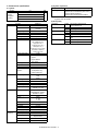
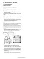
1
SERVICE MANUAL CODE: 00ZARM208/A1E DIGITAL LASER COPIER/ PRINTER (For U.S.A) MODEL AR-M208 CONTENTS This Service Manual describes only the differences from 00ZAR275//A1E. The items which are not described in this Manual are common with the 00ZAR275//A1E. [1] NOTE FOR SERVICING. . . . . . . . . . . . . . . . . . . . . . . . . . . . . . . . . 1-1 [2] SYSTEM CONFIGURATION . . . . . . . . . . . . . . . . . . . . . . . . . . . . . 2-1 [3] SPECIFICATIONS . . . . . . . . . . . . . . . . . . . . . . . . . . . . . . . . . . . . . 3-1 [4] CONSUMABLE PARTS . . . . . . . . . . . . . . . . . . . . . . . . . . . . . . . . . 4-1 [5] UNPACKING AND INSTALLATION . . . . . . . . . . . . . . . . . . . . . . . . 5-1 [6] EXTERNAL VIEW AND INTERNAL STRUCTURE . . . . . . . . . . . . 6-1 [7] ADJUSTMENTS, SETTING . . . . . . . . . . . . . . . . . . . . . . . . . . . . . . 7-1 [8] SIMULATION . . . . . . . . . . . . . . . . . . . . . . . . . . . . . . . . . . . . . . . . . 8-1 [9] TROUBLE CODE LIST. . . . . . . . . . . . . . . . . . . . . . . . . . . . . . . . . . 9-1 [10] DISASSEMBLY, ASSEMBLY AND MAINTENANCE . . . . . . . . . . 10-1 [11] OTHERS . . . . . . . . . . . . . . . . . . . . . . . . . . . . . . . . . . . . . . . . . . . . 11-1 Parts marked with “ ” are important for maintaining the safety of the set. Be sure to replace these parts with specified ones for maintaining the safety and performance of the set. SHARP CORPORATION This document has been published to be used for after sales service only. The contents are subject to change without notice. CAUTION This product is a class 1 laser product that complies with 21CFR 1040.10 and 1040.11 of the CDRH standard and IEC825. This means that this machine does not produce hazardous laser radiation. The use of controls, adjustments or performance of procedures other than those specified herein may result in hazardous radiation exposure. This laser radiation is not a danger to the skin, but when an exact focusing of the laser beam is achieved on the eye’s retina, there is the danger of spot damage to the retina. The following cautions must be observed to avoid exposure of the laser beam to your eyes at the time of servicing. 1) When a problem in the laser optical unit has occurred, the whole optical unit must be exchanged as a unit, not as individual parts. 2) Do not look into the machine with the main switch turned on after removing the developer unit, toner cartridge, and drum cartridge. 3) Do not look into the laser beam exposure slit of the laser optical unit with the connector connected when removing and installing the optical system. 4) The middle frame contains the safety interlock switch. Do not defeat the safety interlock by inserting wedges or other items into the switch slot. Warning! This product is a class A product. If it is operated in households, offices or similar surroundings, it can produce radio interferences at other appliances, so that the user has to take adequate countermeasures. VAROITUS! CLASS 1 LASER PRODUCT LAITTEEN KÄYTTÄMINEN MUULLA KUIN TÄSSÄ KÄYTTÖOHJEESSA MAINITULLA TAVALLA SAATTAA ALTISTAA KÄYTTÄJÄN TURVALLISUUSLUOKAN 1 YLITTÄVÄLLE NÄKYMÄTTÖMÄLLE LASERSÄTEILYLLE. LASER KLASSE 1 LUOKAN 1 LASERLAITE VARNING OM APPARATEN ANVÄNDS PÅ ANNAT SÄTT ÄN I DENNA BRUKSANVISNING SPECIFICERATS, KAN ANVÄNDAREN UTSÄTTAS FÖR OSYNLIG LASERSTRÅLNING, SOM ÖVERSKRIDER GRÄNSEN FÖR LASERKLASS 1. KLASS 1 LASERAPPARAT CAUTION INVISIBLE LASER RADIATION, WHEN OPEN AND INTERLOCKS DEFEATED. AVOID EXPOSURE TO BEAM. VARO ! VORSICHT UNSICHTBARE LASERSTRAHLUNG, WENN ABDECKUNG GEÖFFNET UND SICHERHEITSVERRIEGELUNG ÜBERBRÜCKT. NICHT DEM STRAHL AUSSETZEN. VARNING ! AVATTAESSA JA SUOJALUKITUS OHITETTAESSA OLET ALTTIINA NÄKYMÄTTÖMÄLLE LASERSÄTEILYLLE ÄLÄ KATSO SÄTEESEEN. OSYNLIG LASERSTRÅLNING NÄR DENNA DEL ÄR ÖPPNAD OCH SPÄRREN ÄR URKOPPLAD. BETRAKTA EJ STRÅLEN. – STRÅLEN ÄR FARLIG. ADVARSEL USYNLIG LASERSTRÅLNING VED ÅBNING, NÅR SIKKERHEDSBRYDERE ER UDE AF FUNKTION. UNDGÅ UDSAETTELSE FOR STRÅLNING. Laserstrahl LASER RADIATION WHEN OPEN AND INTERLOCKS DEFEATED. LASERSTRÅLING NÅR DEKSEL ÅPNES OG SIKKERHEDSLÅS BRYTES. CAUTION INVISIBLE AVOID EXPOSURE TO BEAM. ADVERSEL USYNLIG UNNGÅ EKSPONERING FOR STRÅLEN. UNSICHTBARE LASERSTRAHLUNG, WENN ABDECKUNG GEÖFFNET UND OSYNLIG LASERSTRÅLNING NÄR DENNA DEL ÄR ÖPPNAD OCH SPÄRREN ÄR VORSICHT SICHERHEITSVERRIEGELUNG ÜBERBRÜCKT. NICHT DEM STRAHL AUSSETZEN. VARNING URKOPPLAD. BETRAKTA EJ STRÅLEN. – STRÅLEN ÄR FARLIG. LASERSTRÅLNING VED ÅBNING, NÅR SIKKERHEDSBRYDERE ER AVATTAESSA JA SUOJALUKITUS OHITETTAESSA OLET ALTTIINA NÄKYMÄTTÖMÄLLE ADVARSEL USYNLIG UDE AF FUNKTION. UNDGÅ UDSAETTELSE FOR STRÅLNING. VARO! LASERSÄTEILYLLE ÄLÄ KATSO SÄTEESEEN. CLASS 1 LASER PRODUCT LASER KLASSE 1 LASER WAVE – LENGTH : 795 ± 15 mm Pulse times : 0.481 ms/6 mm Out put power : 5 mW Disconnect the AC cord before servicing the unit. The AR-M208 is a modified version of the AR-235/275, and is provided with the RSPF and the GDI printer function. (For contents of the RSPF, refer to the AR-RP3 Service Manual.) The different points of the AR-M208 from the AR-235/275 are shown in the table below. Item [1] [2] [3] AR-235/275 Page Content NOTE FOR SERVICING SYSTEM CONFIGURATION 2-1 1. Structure Block diagram 2-2 2. System outline (Options) SPECIFICATIONS 3-1 2. - B. - (2) Picture quality mode 2. - B. - (3) Copy magnification ratio 3-2 3-3 2. - B. - (4) - b. Multi copy speed (sheets/ minute) 2. - B. - (6) - a. Image process 2. - B. - (6) - d. Resolution 3. - C. - (6) Scanning speed 3. - E. Image process section 3-4 [4] [5] [6] [7] 6. “Sharp Printer Language with Compression (SPLC)” Printer mode CONSUMABLE PARTS UNPACKING AND INSTALLATION EXTERNAL VIEW AND INTERNAL STRUCTURE 6-1 1. External view 6-4 5. Sensor ADJUSTMENTS, SETTING 7-2 2. - A. - (3) Developing bias voltage adjustment (SIM 8-1) 2. - A. - (4) Grid bias voltage adjustment (High mode) (SIM 8-2) 2. - A. - (5) Grid bias voltage adjustment (Low mode) (SIM 8-3) 2. - B. - (2) Print start position adjustment 7-3 2. - B. - (5) Paper off center adjustment 2. - B. - (6) Left edge void area adjustment 7-9 2. - C. - (1) Copy mode (SIM46-2) [8] SIMULATION 8-7 Sim3-3 8 - 10 Sim8-1 8 - 11 Sim8-2, Sim8-3 Sim8-10 8 - 12 Sim8-11, Sim8-12 8 - 13 Sim9-1 AR-M208 Content of change Remarks No change Block diagram is changed. Refer to page 2-1, 2 of the appendix. Main unit AR-235/275 is changed into AR-M208 Options AR-RP3 is provided as a standard equipment. AR-VR3, AR-SP4 is deleted. AR-D11 is changed into AR-D11N. AR-D12 is changed into AR-D12N. AR-FN5 is changed into AR-FN5N. Super Photo mode is deleted. SPF is deleted. Fixed magnification mode of RSPF is changed. 1200dpi mode is deleted. Change Refer to page 3-1 – 4 of the appendix. Super Photo mode is deleted. Change (Pseudo resolution is deleted.) 1200dpi is deleted. Imaging speed of 1200 dpi is deleted. Toner Life is changed. “Sharp Printer Language with Compression (SPLC)” Printer mode is added. Maintance Kits changed. No change Platen cover (optional) is changed into RSPF Added (Dehumidification heater switch) Change (Abbreviation code is added/change.) Refer to page 6-1 – 2 of the appendix. Default of SUPER PHOTO of "5: Super" in the table of Adjustment specification is changed to disabled. Refer to SIM8-1, 2, and SIM8-3 on page 8-1, 2 of the appendix. Sim50-5 Refer to SIM50-5 on page 8-10 of the appendix. Modulation means for compulsory specification of tray are added. (Remark) Sim50-10 Modulation means for compulsory specification of tray are added. (Remark) Sim50-1 Modulation means for compulsory specification of tray are added. (Remark) (16) SPF scan position auto adjustment is added. Refer to SIM50-10 on page 8-11 of the appendix. Refer to SIM50-1 on page 8-10 of the appendix. Refer to page 7-1 of the appendix. SUPER PHOTO in the table of Adjustment specification is deleted. 4: FM-1200 is changed to disabled. Default of SUPER PHTO is changed to disabled. Note is added. Default of 7: DENS1(1200) to 11: DENS5(1200) is changed to disabled. 2: DFM1200 and 4: DMR1200 are changed to disabled. I Refer to page 8-1 – 13 of the appendix. Item [8] Page 8 - 14 AR-235/275 Content Sim9-5 Sim21-1 8 - 15 Sim22-3 Sim22-5 8 - 16 Sim22-10 8 - 18 Sim22-12 Sim24-15 Sim25-1 8 - 20 8 - 21 Sim26-6 Sim26-12, Sim26-14 Sim26-22 8 - 22 8 - 23 8 - 26 8 - 27 Sim26-41 Sim26-57 Sim43-1 Sim44-34 Sim46-2 8 - 29 Sim46-7 Sim46-18 Sim46-19 8 - 31 8 - 32 8 - 33 [9] [10] [11] Sim46-20 Sim50-1 Sim50-5 Sim50-6 Sim50-10 Sim51-1 Sim51-2 Sim51-9, Sim53-8 8 - 34 Sim64-1 8 - 39 Sim67-11, Sim67-14, Sim67-17, Sim67-18 8 - 40 Sim67-20 TROUBLE CODE LIST DISASSEMBLY, ASSEMBLY AND MAINTENANCE 10 - 1 1. Maintenance table OTHERS 11 - 2 2. User programs AR-M208 Content of change Default of 2: 1200dpi is changed to disabled. Change/Added (Display, Item, Content, Setting range, Default) Display of jam history is added. Display is changed. Note is added. Label code display content is added. Display content is changed. (SPEED, IMC MEM) Display item is changed. (PCL → PRINTER) Model code is changed. (SPF, RSPF, Finisher, 1 tray paper feed unit, 2 tray paper feed unit, PRINTER) Note is added. Display of jam history is added. Note is added. Display is changed. (1200dpi: Disabled) Note is added. Display item is changed. (12: TAIPEI → TAIWAN) Note is added. Display, Setting range, and Default are changed. Item is changed. (5: ITALY → ITALIAN) (14: CZECHOSLOVAK → CZECH) Item is added. (20: TAIWANESE) Added Display, Display items, Setting range is changed. Default of 2: 1200dpi is changed to disabled. Display, Default is changed. Default of 5: SUPER PHOTO is changed to disabled. Note is added. Inhibited to use Default of 5: SUPER PHOTO is changed to disabled. Note is added. Default of 5: 1200dpi PHOTO is changed to disabled. Display, Default is changed. Modulation means for compulsory specification of tray are added. (Remark) Remarks Refer to page 8-1 – 13 of the appendix. Display, Default is changed. Modulation means for compulsory specification of tray are added. (Remark) Default of 2: 1200dpi is changed to disabled. Modulation means for compulsory specification of tray are added. (Remark) Added Change Note is added. No change Gear is added to transfer unit. Account Limit, Initial Conditions, and Message Time are deleted. II Refer to page 10-1 of the appendix. AR-M208 SYSTEM CONFIGURATION 2 - 1 TRCL; Vertical transport roller clutch 2 PPD1 ; Paper Pass Detector PAP1 ; Paper Empty LUD1 ; Lift Up Detector CSS1 ; Casette Detector DRS1 ; Door Detector PCL1 ; Pick Up Clutch LUM1 ; Lift Up Motor OP-UP cassette Paper Feed Motor OP interface PWB Pout Gate Solenoid CN140 CN129 CN103 CN104 CN131 CN28 Pout 2 Ssensor HPSIZE2: Handpaper Size Sensor 2 HPWS: Handpaper Width Sensor HPSOL: Handpaper PickUp Solenoid LUD2 ; Lift Up Detector CSS2 ; Casette Detector Fuser-Lamp THERMISTER Fuser Unit PSRSOL: Paper Stop Roller Sol. LUM2 ; Lift Up Motor LUM1H: Lift Up Motor PCL1H: PickUp Cluth CSS1H: Cassette Detector PCL2 ; Pick Up Clutch DRS2 ; Door Detector HPSIZE1: Handpaper Size Sensor 1 PAP2 ; Paper Empty HPTRAY2: HandpaperTRAY Sensor 2 HPTRAY1: HandpaperTRAY Sensor 1 HPIN: Handpaper IN Sensor HPEMPTY: HandpaperEmpty sensor Manual feed unit Main body paper feed load CN126 CN118 2nd POUT COVER SENSOR PPD2 ; Paper Pass Detector OP-LO cassette Paper Feed Motor Multi-step cassette unit (Optional) TRCLH: Vertical transport roller clutch PCL2H ; Pick Up Clutch LUM2H ; Lift Up Motor CSS2H ; Casette Detector DRS2H ; Door Detector PPD2H ; Paper Pass Detector PAP2H ; Paper Empty LUD2H ; Lift Up Detector OP interface PWB PCS1H ; Pick Up Solenoid 2nd cassette unit (Optional) Sol Drum Initial PPD1H(PIN):Paper IN Sensor Paper Remove Sensor Paper Out Duplex Duplex-Motor LUD1H ; Lift Up Detector PAP1H ; Paper Empty Main body cassette unit Shifter-Motor Fuser Cooling Fan 2 Sensor HP Shifter SPF-DupSO Pout Sensor SPF-pressure release SOL Fuser Cooling Fan 1 SPF-Motor CN113 Paper Full Sensor MAIN-Motor Copy-Lamp Heater Defog AB FAX-OP-PWB OPERATION PANEL CN132 INCH Vender Coin COPY-OP-PWB LCD CN108 CCD-PWB IMC PWB Sensor Mirror HP Paper Size Sensor Cn130 (AB Area ONLY) SPF-CON-PWB CN123 CN115 Sensor CN125 (INCH Area ONLY) L2 CN139 Cover CN136 L1 CN134 Scanner CN111 SPF BOOK Sens D-Sub 25pin InterLock Switch APC-PWB LSU-PWB D-Sub 9pin MCU-PWB CN117 D-Sub 15pin BD-Sensor BD-PWB HVU Power Unit Power Supply (CE Only) Reactor PS-SW PS Cooling Fan Ozon Fan Defog Heater Rear edge plate HP sensor Paper Size Detector Rear edge plate drive motor Transport select gate right solenoid Rear edge plate drive solenoid (Optional) FIN main motor (Optional) PCL PWB GDI PWB Tray position sensor Upper Lift-up drive control sensor USB PWB Upper alignment plate drive solenoid Tray lift-up motor Transport select gate right Paper position sensor solenoid 2 Tray off-set motor Shutter drive solenoid Tray position sensor Lower Paper exit roller clutch Off-set position sensor Side guide plate motor No. 2 tray paper exit sensor Staple HP sensor Staple operation motor Stapler No. 1 tray paper exit sensor Self priming sensor Tray paper empty sensor Side guide plate HP sensor FAX PWB JAM process PG open/close sensor Tray JAM process sensor Staple supply cover open/close sensor Cartridge empty sensor Staple empty sensor Finisher Unit (Optional) Mother PWB Down-Load-CON Option interface PWB Polygon-Motor Toner-Motor (include CRSM) UNIT DEV CN135 SPF Paper Size Sens (x5) CN107 SPF Paper Empty CN112 SPF-PSOL CN106 SPF PS Sens CN110 SPF Cover Sens CN121 Mirror-Motor CN109 SPF-SEN-PWB CN102 TRAYPAPER SENSOR FINISHER PWB SPF/RSPF Unit (Optional) [2] SYSTEM CONFIGURATION 1. Structure A. Hardware Block diagram (It cannot be equipped with GDI PWB and PCL PWB simultaneously.) 2. System outline (Options) Option Item 500-sheet paper feed unit 2X500-sheet paper feed unit Job separator tray kit Finisher Facsimile expansion kit Fax memory 2MB 4MB 8MB Printer expansion kit Print server card Network scanner expansion kit Bar code font kit PS3 expansion kit Model AR-D11N AR-D12N AR-TR3 AR-FN5N AR-FX4 AR-MM5 AR-MM6 AR-MM7 AR-P11 NOTE When the printer board is set up on the machine, the function of duplex can be automatically detected on printer mode. AR-NC5J AR-NS2 AR-PF1 AR-PK1 For details of the options, refer to the Service Manual of each option. (1) Main unit AR-M208 (2) Options AR-D11N 500-sheet paper feed unit AR-D12N 2 x 500-sheet paper feed unit AR-TR3 Job separator tray kit AR-FN5N Finisher AR-MM5/MM6/MM7 2/4/8MB Fax memory AR-NS2 Network scanner expansion kit AR-PF1 Bar code font kit AR-FX4 Facsimile expansion kit AR-P11 Printer expansion kit AR-NC5J Print server card Do not use the PRINTER UTILITY CO-ROM that accompanied the AR-P11 and AR-PK1 to install the software. AR-M208 SYSTEM CONFIGURATION 2 - 2 AR-PK1 PS3 expansion kit [3] SPECIFICATIONS 3. Engine specifications This model is designed as an SPLC printer, and can be extended for use as a PCL6/PS3/NC/scanner by options. For details, refer to the Service Manual of the AR-P11/AR-PK1/AR-NC5J/AR-NS2. B. Copy mode (2) Picture quality mode Density adjustment step 1 step 5 steps 5 steps 5 steps Auto mode Text mode Text/Photo mode Photo mode Toner save mode Selectable Selectable Selectable — (3) Copy magnification ratio Copy magnification ratio Zoom width Fixed magnification mode Independent magnification width Magnification precision (6) Scanning speed 122mm/sec (600 dpi: magnification ratio 100%) E. Image process section 2. Operation specifications Picture quality mode C. Optical (Image scanning) section Magnification range/fixed magnification 25 to 400% (50 to 200% for RSPF) 5R+5E AB Series: 25, 50, 70, 81, 86, 100, 115, 122, 141, 200, 400% Inch Series: 25, 50, 64, 77, 95, 100, 121, 129, 141, 200, 400% (However, 25%/400% is inhibited when RSPF is used.) 25 to 400% for horizontal/vertical (50 to 200% for RSPF) Normal copy: 100%±1.0% Enlargement copy: Set magnification ±1.0% Reduction copy: Set magnification ±1.0% (4) Job speed b. Multi copy speed (sheets/minute) Imaging speed Photo Type conductor LIFE Toner Type LIFE Charge System Voltage System Voltage Transfer Exposure Developing Separation Discharge Cleaning 6. “Sharp Printer Language with Compression (SPLC)” Printer mode A. Basic specification Item Print Speed Resolution Smoothing Toner Save Mode Input tray Copy magnification Document Size A3 B4 A4 (Horizontal feed) A4 (Vertical feed) B5 (Horizontal feed) B5 (Vertical feed) 11" × 17" 8-1/2" × 14" 8-1/2" × 13" 8-1/2" × 11" (Horizontal feed) 8-1/2" × 11" (Vertical feed) A5/INV Normal copy (100%) / Reduction copy (50% to 99%) / Enlargement copy (101% to 200%) 12.5 14 20 16 20 18 12.5 14 15 20 16 20 Finisher Printer driver Manual (Online manual) Platform Support OS (Printer Driver) ∗ The slowest speed is listed in enlargement/reduction copy. ∗ Single-side copy (6) Picture quality a. Image process Picture quality mode Auto mode Text mode Text/Photo mode Photo mode Image process (Software) • 2 gradations • Area separation • Error diffusion d. Resolution Scan Output Main scanning direction 400 dpi 600 dpi 600 dpi : 122 mm/sec. OPC drum (dia. 30mm) 50,000 sheets Developer (Black) 30,000 sheets (Toner, life: 25k, Developer life: 50k) (–) DC scorotron (saw tooth) 560µA constant electric current Transfer roller 18µA (electric current) Xenon lamp Dry, 2-component magnetic brush development (–) DC corotron — Blade Sub scanning direction 600 dpi 600 dpi AR-M208 SPECIFICATIONS 3 - 1 Detail 15ppm: 600dpi (including transfer from PC) 20ppm: ROPM 600dpi 1200dpi x 600dpi Standard 4 Multi size tray 1 Multi Bypass tray (Depending on conditions of the machine and option installation.) Option Standard Standard IBM PC/AT (Include compatible machine) Windows 95/98/Me Windows NT 4.0 Workstation (SP5 or later) Windows 2000 Professional Windows XP Home/Professional Edition C. Printer driver specification (3) System requrement (1) System Machine IBM PC/AT (Include compatible machine) OS GDI Paper IBM PC/AT (Include compatible machine) Operating system Windows 95/98/Me Windows NT 4.0 Workstation (SP5 or later) Windows 2000 Professional Windows XP Home/Professional Edition Windows 95/98/Me Windows NT 4.0 Workstation (SP5 or later) Windows 2000 Professional Yes Windows XP Home/Professional Edition Function Copies Collate N-up printing N-up Order N-up Border Finishing User Setting Paper Size Custom Paper Size Paper Source Note: Hardware requirements such as CPU and RAM for your operating system must be satisfied. (4) Print quality (2) Printing function specification Main Computer GDIDriver 1-999 Collate Uncollate 2/4 Z Yes/No Staple Yes/No Yes A3 / B4 / A4 / B5 / A5 B6 / A6 / Ledger(11x17) / Legal (8.5 x 14) / Foolscap (8.5 x 13) / Letter (8.5 x 11) / Invoice (5.5 x 8.5) / Folio / Executive / COM-10 / DL/C5 / 8K / 16K 1 size • Auto Select Resolution 600dpi Smoothing On* Off On Off* On Off* Toner Save Mode Photo Enhancement 2 Gradation print * Default • Bypass • Bypass Manual Fit to Page Image Orientation Transparency print Output Tray Selection Advanced Print Quality Smoothing Toner save Photo Enhancement 2 Gradation print Image Adjustment Water-mark Watermark User setting Position Configuration *(Manual) Size Angle Gray Scale Edit Font On first page only ROPM Input Trays Output Tray Options Set Tray Status About • Tray 1/2/3/4 Yes / No Portrait / Landscape Yes/No • Center Tray • Job Separator Tray • Finisher Offset tray Normal Draft Photo Yes / No Yes / No Yes/No Yes / No Brightness : 0 to 100 Contrast : 0 to 100 (None) / TOP SECRET / CONFIDENTIAL / DRAFT / ORIGINAL / COPY Add / Update / Delete Center X: ±50 Y : ±50 6 to 300 ±90 0 to 255 Yes Yes / No Yes / No Two / Three / Four trays None / Job Separator / Staple Finisher Yes Yes AR-M208 SPECIFICATIONS 3 - 2 On Off* Print quality is selected from Normal*/Draft/Photo. Smoothing function is ON. Smoothing function is OFF. Toner save function is ON. Toner save function is OFF. Photo enhancement function is ON. Photo enhancement function is OFF. 2-Gradation print function is ON. 2-Gradation print function is OFF. (5) Paper handling specifications a. Paper feed direction Limitations on tray/functions for support paper Paper feed tray Paper name A3 A4 A5 A6 B4 B5 B6 Ledger Letter Legal Executive Folio Invoice Foolscap 8K 16K DL C5 Com10 Custom Paper size 297 x 420 mm 210 x 297 mm 148 x 210 mm 105 x 148 mm 257 x 364 mm 182 x 257 mm 128 x 182 mm 11 x 17 inch 8.5 x 11 inch 8.5 x 14 inch 7.25 x 10.5 inch 8.3 x 13 inch 5.5 x 8.5 inch 8.5 x 13 inch 270 x 390 mm 195 x 270 mm 110 x 220 mm 162 x 229 mm 4.125 x 9.5 inch W: 100 to 297 mm L: 148 to 431.8 mm Manual tray Yes Yes Yes Yes Yes Yes Yes Yes Yes Yes Yes Yes Yes Yes Yes Yes Yes Yes Yes Yes Tray 1 Tray 2 Tray 3 Tray 4 Yes Yes Yes N/A Yes Yes N/A Yes Yes Yes N/A N/A Yes Yes Yes Yes N/A N/A N/A Yes Yes N/A N/A Yes Yes N/A Yes Yes Yes N/A N/A N/A Yes Yes Yes N/A N/A N/A Yes Yes N/A N/A Yes Yes N/A Yes Yes Yes N/A N/A N/A Yes Yes Yes N/A N/A N/A Yes Yes N/A N/A Yes Yes N/A Yes Yes Yes N/A N/A N/A Yes Yes Yes N/A N/A N/A Center tray Yes Yes Yes Yes Yes Yes Yes Yes Yes Yes Yes Yes Yes Yes Yes Yes Yes Yes Yes N/A N/A N/A N/A Yes Setting direction toward paper feed port = Long side Setting direction toward paper feed port = Short side Transfer direction Transfer direction (6) Print enable area Actual page size Paper Size A3 B4 A4 B5 A5 Ledger Legal Letter Invoice Foolscap Folio Executive COM-10 C5 DL Print area Logic paper size HP/GL picture frame AR-M208 SPECIFICATIONS 3 - 3 Paper exit tray Upper Offset tray tray Yes Yes Yes Yes Yes N/A N/A N/A Yes Yes Yes Yes Yes N/A Yes Yes Yes Yes Yes Yes Yes N/A Yes N/A Yes N/A Yes Yes Yes Yes Yes Yes Yes N/A Yes N/A Yes N/A N/A Function N/A Staple Fit page Yes Yes N/A N/A Yes Yes N/A Yes Yes Yes N/A N/A N/A Yes N/A N/A N/A N/A N/A Yes Yes Yes Yes Yes Yes Yes Yes Yes Yes Yes Yes Yes Yes Yes Yes Yes Yes Yes N/A N/A A B C D E F G H 7014 6070 4960 4298 3508 6600 5100 5100 3300 5100 4980 4350 2474 3826 2598 9920 8597 7014 6070 4960 10200 8400 6600 5100 7800 7800 6300 5700 5408 5196 6730 5786 4676 5770 3224 6300 4800 4800 3000 4800 4680 4050 2174 3542 2314 142 142 142 142 142 150 150 150 150 150 150 150 150 142 142 100 100 100 100 100 100 100 100 100 100 100 100 100 100 100 300 300 300 300 300 300 300 300 300 300 300 300 300 300 300 6814 5870 4760 4098 3308 6400 4900 4900 3100 4900 4780 4150 2274 3626 2398 0 0 0 0 0 0 0 0 0 0 0 0 0 0 0 (7) Print reference Logic paper size HP/GL picture frame Paper Size A3 B4 A4 B5 A5 Ledger Legal Letter Invoice Foolscap Folio Executive COM-10 C5 DL A B C D E F G H 9920 8597 7014 6070 4960 8400 8400 6600 5100 7800 7800 6300 5700 5408 5196 7014 6070 4960 4298 3508 5100 5100 5100 3300 5100 4980 4350 2474 3826 2598 9684 8361 6778 5830 4720 8160 8160 6360 2860 7560 7560 6060 3460 5172 4960 118 118 118 118 118 120 120 120 120 120 120 120 120 118 118 100 100 100 100 100 100 100 100 100 100 100 100 100 100 100 300 300 300 300 300 300 300 300 300 300 300 300 300 300 300 9720 8397 6814 5870 4760 8200 8200 6400 4900 7600 7600 6100 5500 5208 4996 0 0 0 0 0 0 0 0 0 0 0 0 0 0 0 Origin ABCDEFGHIJKLMN 12345 abc Paper feed direction Actual page size Print area This machine employs the center reference system. Since the digital copier is not provided with the tray size detection feature, formatting and center distribution are performed not by the actual paper size but by the paper size specified by the computer. Actual paper size Size specified by the HOST Center reference line D. Interface Interface IEEE 1284 (Parallel interface) USB 1.1 E. System outline The GDI-PWB is provided with IEEE1284 I/F on the host side, and the 16-bit bi-directional data bus I/F and UART on the machine side. Transfer of image data with the IMC-PWB is performed with this 16-bit bi-directional data bus. Command status information with the engine is processed with UART. This unit is installed to the position of PCL-PWB on the conventional AR-235/275. JBIG compression data sent from the host are transferred to the IMC PWB, where the data are extracted to be VIDEO data, and sent through the MCU PWB to the LSU. M-bus ∗ Top margin CCD The set value is received from the digital copier, and data are made according to the set value. ∗ Left margin Since the paper size sensor is not set, the digital copier cannot recognize the size and direction of paper which is actually inserted. Therefore, the left margin is set according to the paper size specified in the print data sent from the computer, and print process is performed. If the computer does not specify the paper size, or in the case of the custom size, the left margin is set according to the default paper size. MCU Print Engine Image process ASIC CPU IMC CPU Page memory Extraction JBIGLite UART Command status JBIG data GDI CPU ASIC Compressed memory JBIG printer driver Data through : Data flow AR-M208 SPECIFICATIONS 3 - 4 IEEE1284 Header + JBIG data PC [4] CONSUMABLE PARTS 1. List A. SEC/LAG No. Item Content 1 Toner CA (black) w/IC Toner Vinyl bag 2 Developer Developer (Developer; Net weight 500g) 3 Drum kit Drum 4 Upper heat roller kit Upper Heat Roller Fusing gear Upper heat roller bearing Fusing separation pawl (upper) 5 Lower heat roller kit Lower Heat Roller Fusing separation pawl (lower) Fusing busing (lower) 6 100K maintenance kit Drum Separation Unit Transfer roller unit 7 MC unit MC unit 8 Cleaner Blade Cleaner Blade 9 Drum frame unit Drum frame unit ×10 ×10 ×10 Life 25K (×10) 50K (×10) Model name Remarks AR-270MT Life setting by A4 (8.5"×11") 6% document MT=NT*10 AR-270MD MD=ND*10 ×1 ×1 ×1 ×2 ×4 50K 150K AR-270DR AR-271UH ×1 ×4 300K AR-271LH 100K AR-270KA1 ×2 ×2 ×1 ×10 ×10 ×1 50K (×10) 50K (×10) 200K AR-270MC AR-270CB AR-271DU * The life of the toner reception seat welded to the drum frame is 200K, and it can be used up to 4 times. (Supplied as a drum frame unit.) * Drum frame unit contains all the drum unit parts excluding Drum and Drum fixing plate. 10 Staple Cartridge Staple Cartridge 11 Transfer roller unit 12 Paper feed roller kit 13 Fusing unit Transfer roller unit Paper feed roller kit Fusing unit ×3 3000 staples ×3 ×1 100K ×1 100K ×1 150K AR-SC1 AR-271TX AR-271IR AR-271FU * The other maintenance parts than the above are supplied as service parts. AR-M208 CONSUMABLE PARTS 4 - 1 Paper feed roller, pickup roller, separation sheet [6] EXTERNAL VIEW AND INTERNAL STRUCTURE 1. External view 1 10 9 2 3 8 11 7 12 13 14 6 5 No. 1 15 4 Name Function/Operation Duplex documents are automatically reversed to perform continuous copying of the front and the back. Finished copies are deposited in the paper output tray. Open to remove misfeeds and for copier servicing. Each tray holds 500 sheets of copy paper. Press to turn on the heater to prevent dew condensation inside the copier and moisture absorption of paper. Press to turn copier power on and off. Use to move the copier. All copier controls are located here for easy operation. Place the document to be copied here. Open to remove misfeeds when an optional job separator tray kit or finisher is installed. Open to remove misfeeds. Lift and pull to open the side cover. Adjust to the width of the copy paper. Special papers (including transparency film) and copy paper can be fed from the bypass tray. Pull out when feeding large paper such as 8-1/2" x 14" and 11" x 17". RSPF 2 3 4 5 Paper output tray Front cover Paper trays Dehumidification heater switch ∗ 6 7 8 9 10 11 12 13 14 15 Power switch Handles Operation panel Original table Upper exit area cover Side cover Side cover handle Bypass tray guides Bypass tray Bypass tray extension ∗ Dehumidification heater switch (DH POWER) • In regions at a high temperature and a high humidity This copier is equipped with a dehumidification heater, which prevents dew condensation inside the copier and moisture absorption of paper in the paper trays. If dew condensation occurs and causes moisture absorption of paper, image quality may be deteriorated and paper misfeeds may occur frequently. It is recommended that the dehumidification heater switch be left in the “ON” position in the following cases even after the power switch is turned off. • In a low temperature season such as winter (When a sudden temperature change occurs, for example, immediately after room heating is turned on, dew condensation may occur.) • In a high temperature and high humidity season such as summer or rainy season (Depends on the use conditions. The reference is 60% (humidity) or more.) On NOTES: • When using the dehumidification heater, do not remove the power cord from the outlet. Doing so will stop the heater. • If an optional 500-sheet paper feed unit or 2x500-sheet paper feed unit is installed, the heater in the unit will also be turned on when the dehumidification heater switch of the copier is turned on. AR-M208 EXTERNAL VIEW AND INTERNAL STRUCTURE 6 - 1 5. Sensor No. 2 18 Code 19 Manual feed length detection sensor 1 Door switch 20 2nd right door switch DRS1A 21 2nd cassette paper pass sensor 2nd cassette paper upper limit detection sensor 2nd cassette paper empty sensor 1st cassette paper upper limit detection sensor 1st cassette paper empty sensor Center tray paper YES/NO sensor Right cabinet door switch 2nd paper exit sensor PPD1A 3 1 Name HPSIZE1 SW24V 4 29 5 28 6 27 22 7 8 26 9 23 10 11 12 24 13 14 25 24 30 23 15 16 25 17 26 18 22 21 20 No. Name 19 28 Code 1 Original size sensor DSIN0 2 Mirror home position sensor MHPS 3 4 Document cover sensor Document size sensor 5 1st paper exit sensor POUT 6 SFTHP 8 Shifter home position sensor Paper exit sensor (DUP side) Thermistor 9 Thermostat 10 Manual feed paper entry sensor HPIN 11 1st cassette (paper tray) detection Manual feed paper empty sensor 2nd cassette (paper tray) detection Manual feed width detection volume Manual paper feed tray empty sensor 2 Manual paper feed tray empty sensor 1 Manual feed length detection sensor 2 CSS1H 7 12 13 14 15 16 17 27 OCCOVER DSIN3 PDPX RTHIN HPEMPTY CSS1A HPWS HPTRAY2 HPTRAY1 HPSIZE2 Function and operation Document size detection Mirror (scanner) home position detection Document cover open/close detection Document size detection 1st paper exit detection Shifter home position sensor detection Paper exit detection 29 30 2nd paper exit full detection sensor 1st cassette paper pass sensor Fusing temperature detection Abnormal high temperature detection in the fusing section Sensor of paper entry from the manual paper feed tray, the 2nd/multi-stage desk, or the DUP 1st cassette (paper tray) empty detection Manual feed paper empty detection 2nd cassette (paper tray) empty detection Manual feed paper width detection Manual feed tray position detection Manual feed tray position detection Manual feed paper length detection AR-M208 EXTERNAL VIEW AND INTERNAL STRUCTURE 6 - 2 LUD1A PAP1A LUD1H PAP1H TRAYPAPER POUTCOV POUT2 PFULL2 PIN Function and operation Manual feed paper length detection Front door and side door open/close detection Side door open/close detection 2nd cassette paper pass 2nd cassette paper upper limit detection 2nd cassette paper empty detection 1st cassette paper upper limit detection 1st cassette paper empty detection Center tray paper YES/NO detection Right cabinet door open/close detection 2nd paper exit detection 2nd paper exit section full detection 1st cassette paper pass [7] ADJUSTMENTS, SETTING 2. Copier adjustment B. Mechanism section (16) SPF scan position auto adjustment [Function] Used to adjust the SPF scan position automatically. [Operation] 1) With the SPF or the OC cover open, place a chart of black background on the OC glass. (In the SPF standard model, the SPF glass surface is included.) ∗ Use a black chart (UKOG-0011QSZZ) or prepare a chart as shown below. Chart size: 310 x 470, prepared with cutting sheet No. 791 (Black) or an equivalent one. Reason: To prevent erroneous detection by disturbing light of a fluorescent lamp, etc. 2) Enter SIM53-08, and press [START] button. Outline of SIM: The optical unit is shifted to recognize the boundary between the OC glass and the SPF glass cover. With the same position as the reference, the SPF scan position is automatically adjusted. <Note> • After completion of the SPF scan position auto adjustment, the SPF lead edge adjustment must be executed. (Both surfaces) • There must be no other sheet than the black chart on the glass surface. • Especially when in SPF scan, the center area is scanned in the main scan direction. Be careful to prevent external light from entering the scan area. 3) Check that the lead edge is not shifted. (Both surfaces) (If the original lead edge adjustment has been made properly, even when the scan position is shifted, it is followed automatically.) Place only the black chart on the OC glass. For the SPF standard-provision machine, check that the black chart covers the SPF glass. Placing the black chart The black chart must cover this area. 4) Change the adjustment value of the SPF scan end position. (Change the adjustment value of SIM50-6-3 from 50 to 36.) Change the number of steps for Pin off – scan end position from 1,014 to 986. Be sure to execute this adjustment because an image may be cut off during FAX transmission though copying is normally performed. 5) Change the initial value of the SPF exposure adjustment (SIM4620) from 50 to 53. (For the CCD exposure adjustment with SPF, use the value of the OC adjustment value +3.) There are suffixes of –1 SPF and –2 SPF. Change each of them. AR-M208 ADJUSTMENTS 7 - 1 [8] SIMULATION Code Main Sub 50 1 5 2. Simulation code list Code Main Sub 3 3 8 1 2 3 10 11 12 9 1 5 21 22 1 3 5 10 12 24 25 26 15 1 6 12 14 22 41 43 44 46 57 1 34 2 18 19 20 Function 6 Used to check the operation of the load in the finisher and the control circuit. Used to check and adjust the operation of the developing bias voltage in each copy mode and the control circuit. Used to check and adjust the operation of the main charger grid voltage (high mode) in each copy mode and the control circuit. Used to check and adjust the operation of the main charger grid voltage (low mode) in each copy mode and the control circuit. Used to check and adjust the operation of the developing bias voltage in each printer mode and the control circuit. Used to check and adjust the operation of the main charger grid voltage (high mode) in each printer mode and the control circuit. Used to check and adjust the operation of the main charger grid voltage (low mode) in each printer mode and the control circuit. Used to check and adjust the operation of the load (motor) in the duplex section and the control circuit. Used to adjust the switch back time of the duplex motor. Used to set the maintenance cycle. Used to check the misfeed positions and the number of misfeed at each position. (When the number of misfeed is considerably great, it can be judged as necessary for repair.) Used to check the ROM version of each unit (section). Used to check the system configuration. Used to check the misfeed positions and the number of misfeed at each position. (When the number of misfeed is considerably great, it can be judged as necessary for repair.) Used to clear the scanner mode counter. Used to check the operation of the main drive (excluding the scanner section) and to check the operation of the toner concentration sensor. (The toner concentration sensor output can be monitored.) Used to set the specifications depending on the destination. Used to input the Software Key for E-MAIL RIC. Used to input the Software Key for the PS extension kit. Used to set the specification (language display) for the destination. Used to set whether the automatic magnification ratio select (AMS) is always ON or not when setting the pamphlet (center binding) function. Used to set the model code. Used to set the fusing temperature in each operation mode. Used to adjust the transfer current value. Used to adjust the copy exposure level. Used to adjust the copy contrast. (Inclination) Used to change the image quality in the exposure mode. Used to correct SPF exposure. 10 51 1 2 9 53 8 64 1 67 11 14 17 18 20 Function Used to adjust the copy lead edge position. Used to adjust the print image position (top margin) on the print paper in the print mode. Used to adjust the print image position (top margin) on print paper in the copy mode. (SPF/ RSPF) Used to adjust the print image center position. (Adjustment can be made for each paper feed section.) Used to adjust the OPC drum separation pawl ON time. Used to adjust the contact pressure of paper onto the resist roller in each section (copier paper feed section, duplex paper feed section, SPF paper feed section). (When the print image position varies greatly for the paper or when a lot of paper jam troubles occur, the adjustment is required.) Used to adjust ON/OFF timing of the separation voltage. Used to adjust the mirror unit SPF scan position automatically. For the SPF scan position auto adjustment, the mirror unit is shifted to 11mm before the SPF glass cover edge and is moved by self-boost, and images are scanned in each step, and the position from the glass cover edge is automatically detected. [Adjustment value] Default: 50 Setting range: 1 to 99 Adjustment unit 1 = about 0.127mm Self print Key input = 1 Self print is performed in the 2-by-4 mode (2-line print and 4-line non-print). Key input = 2 Grid print is performed. (1cm, 1-dot width WLT/A3 print (A3 main scan, WLT sub scan)) Used to set the Select-IN signal. Used to check write/comparison of flash programs. Used to clear NVRAM. Used to clear the data area for FLASH ROM Network Scanner Application. Used to check the network connection when a scanner option is installed. 3. Details 3 3-3 Purpose Function (Purpose) Section Item Operation test/check Used to check the operation of the load in the finisher and the control circuit. Sorter/Finisher Operation Operation/procedure The names of the loads which can be operated are displayed. Select the load to be checked with the key. AR-M208 SIMULATION 8 - 1 (Initial screen) When reading a value from the EEPROM, the value of (EEP value *2) + 200 is used as the set value. Therefore, the set value entered must be an even number. If an odd number is entered the entered odd number + 1 is displayed after pressing [OK] key. (Executing screen) Sim3-3 OUTPUT CHECK 1:JGM1 4:FM-1200 2:JGM2 5:EVM 3:FM-600 6:OFM 1/3 EXEC Sim3-3 OUTPUT CHECK 7:STM 10:JGSL1 8:OGSLR 11:JGSL2 9:OGSLL 12:SHTSL 2/3 EXEC 8 During execution, [EXEC] is highlighted. Under this state, press the [BACK] key to interrupt the operation. Side guide plate drive motor Rear edge plate drive motor Finisher main motor (600dpi) Finisher main motot (1200dpi) Tray lift-up motor Tray offset motor Staple operation motor Transport selection gate solenoid (R) Transport selection gate solenoid (L) Rear edge plate drive solenoid Upper alignment plate drive solenoid Shutter drive solenoid Paper exit roller clutch Paper holding solenoid 1:JGM1 2:JGM2 3:FM-600 4:FM-1200 5:EVM 6:OFM 7:STM 8:OGSLR 9:OGSLL 10:JGSL1 11:JGSL2 12:SHTSL 13:T2SCL 14:STGSL Disabled Section Adjustment/Operation test/check Used to check and adjust the operation of the main charger grid voltage (high mode) in each copy mode and the control circuit. Image process (Photoconductor/Developing/Transfer/ Cleaning) Photo conductor After selecting the mode, enter the adjustment value and press the [OK] key, and output will be made for 30sec. The input value is in the increment of –25V. (Initial screen) (Input/Selection screen) (Executing screen) The staple operation motor operates only when there is no cartridge installed. Note:Executable only when the finisher is installed. 8 Sim8-2 MHV(H) COPY 1:AE 3 2:TEXT 5 3:TEXT/PHOTO 5 1/2 Display items Sim8-2 MHV(H) COPY 5:SUPER PHOTO 3 Sim8-2 MHV(H) COPY 5:SUPER PHOTO 3 EXEC [ 1- 8] EXEC [ 1- 8] 3 Content AE (∗) Character Character/Photo Photo Super photo Toner save 1:AE 2:TEXT 3:TEXT/PHOTO 4:PHOTO 5:SUPER PHOTO * 6:TONER SAVE Setting range 1-8 3 Default 3 (–530V) 5 (–580V) 5 (–580V) 5 (–580V) Disabled 2 (–505V) (∗) Linked with the destinations of SIM 26-6. Linked with the auto exposure mode of SIM 46-19-1. 8-1 Section Purpose Function (Purpose) Operation/procedure The finisher main motor operates for 10sec, the staple motor 5 times, the tray lift-up motor one reciprocating operation, other motors max. 20 reciprocating operations from the home position, the solenoid repeats 500msec ON and 500msec OFF 20 times. Purpose Function (Purpose) 8-2 Adjustment/Operation test/check Used to check and adjust the operation of the developing bias voltage in each copy mode and the control circuit. Image process (Photoconductor/Developing/Transfer/ Cleaning) Developer/Toner hopper Operation/procedure After selecting the mode, enter the adjustment value and press the [OK] key, and output will be made for 30sec. (Initial screen) (Input/Selection screen) (Executing screen) Sim8-1 DV BIAS 1:AE 2:TEXT 3:TEXT/PHOTO 1/2 COPY 400 450 450 Sim8-1 DV BIAS COPY 5:SUPER PHOTO 400 Sim8-1 DV BIAS COPY 5:SUPER PHOTO 400 EXEC [200-550] 400 EXEC [200-550] 400 * SUPER PHOTO (5:) cannot be executed. When [OK] or [START] key is pressed, a caution buzzer sounds. (Only the adjustment value can be entered.) NO. 1 2 3 4 5 6 7 8 Set value 480 505 530 555 580 605 630 655 Grid High –480V –505V –530V –555V –580V –605V –630V –655V Grid Low –350V –375V –400V –425V –450V –475V –500V –525V *1. The negative value of the set value corresponds to the grid high output voltage. *2. The set values can be selected from the above 8 patterns only. Display items Content 1:AE 2:TEXT 3:TEXT/PHOTO 4:PHOTO 5:SUPER PHOTO * 6:TONER SAVE AE (∗) Character Character/Photo Photo Super photo Toner save Installation range 200-550 Default 400 (–400V) 450 (–450V) 450 (–450V) 450 (–450V) Disabled 376 (–376V) (∗) Linked with the destinations of SIM 26-6. Linked with the auto exposure mode of SIM 46-19-1. *3. The selected pattern determines the grid high voltage and the grid low voltage. If, for example, the grid high voltage is set to –480V (pattern 1), the grid low voltage is –350V. 8-3 Purpose Function (Purpose) Section * SUPER PHOTO (5:) cannot be executed. When [OK] or [START] key is pressed, a caution buzzer sounds. (Only the adjustment value can be entered.) The minimum increment is 2V. The result of (Set value – 199) / 2 is stored in the EEPROM. Adjustment/Operation test/check Used to check and adjust the operation of the main charger grid voltage (low mode) in each copy mode and the control circuit. Image process (Photoconductor/Developing/Transfer/ Cleaning) Photo conductor Operation/procedure After selecting the mode, enter the adjustment value and press the [OK] key, and output will be made for 30sec. AR-M208 SIMULATION 8 - 2 The input value is in the increment of –25V. (Initial screen) (Input/Selection screen) (Executing screen) Sim8-3 MHV(L) COPY 1:AE 3 2:TEXT 5 3:TEXT/PHOTO 5 1/2 Display items Sim8-3 MHV(L) COPY 5:SUPER PHOTO 3 Sim8-3 MHV(L) COPY 5:SUPER PHOTO 3 EXEC [ 1- 8] EXEC [ 1- 8] 3 Content AE (∗) Character Character/Photo Photo Super photo Toner save 1:AE 2:TEXT 3:TEXT/PHOTO 4:PHOTO 5:SUPER PHOTO * 6:TONER SAVE Setting range 1-8 3 Default 3 (–400V) 5 (–450V) 5 (–450V) 5 (–450V) Disabled 2 (–375V) (∗) Linked with the destinations of SIM 26-6. Linked with the auto exposure mode of SIM 46-19-1. * SUPER PHOTO (5:) cannot be executed. When [OK] or [START] key is pressed, a caution buzzer sounds. (Only the adjustment value can be entered.) NO. 1 2 3 4 5 6 7 8 Set value 480 505 530 555 580 605 630 655 Grid High –480V –505V –530V –555V –580V –605V –630V –655V Grid Low –350V –375V –400V –425V –450V –475V –500V –525V 8-10 Adjustment/Operation test/check Used to check and adjust the operation of the developing bias voltage in each printer mode and the control circuit. Image process (Photoconductor/Developing/Transfer/ Cleaning) Developer/Toner hopper Operation/procedure After selecting the mode, enter the adjustment value and press the [OK] key, and output will be made for 30sec. (Initial screen) (Input/Selection screen) (Executing screen) PRT 400 450 450 Density 1 (600dpi) Density 2 (600dpi) Density 3 (600dpi) Density 4 (600dpi) Density 5 (600dpi) Toner save (600dpi) Density 1 (1200dpi) Density 2 (1200dpi) Density 3 (1200dpi) Density 4 (1200dpi) Density 5 (1200dpi) Installation range 200-550 Default 400 (–400V) 450 (–450V) 450 (–450V) 450 (–450V) 500 (–500V) 350 (–350V) Disabled Disabled Disabled Disabled Disabled The minimum increment is 2V. The result of (Set value – 199) / 2 is stored in the EEPROM. When reading a value from the EEPROM, the value of (EEP value *2) + 200 is used as the set value. Therefore, the set value entered must be an even number. If an odd number is entered the entered odd number + 1 is displayed after pressing [OK] key. Section *3. The selected pattern determines the grid high voltage and the grid low voltage. If, for example, the grid high voltage is set to –480V (pattern 1), the grid low voltage is –350V. Sim8-10 DV BIAS 1:DENS1(600) 2:DENS2(600) 3:DENS3(600) 1/4 1:DENS1(600) 2:DENS2(600) 3:DENS3(600) 4:DENS4(600) 5:DENS5(600) 6:TS(600) 7:DENS1(1200) 8:DENS2(1200) 9:DENS3(1200) 10:DENS4(1200) 11:DENS5(1200) Purpose Function (Purpose) *2. The set values can be selected from the above 8 patterns only. Section Content 8-11 *1. The negative value of the set value corresponds to the grid high output voltage. Purpose Function (Purpose) Display items Sim8-10 DV BIAS PRT 5:DENS5(600) 500 Sim8-10 DV BIAS PRT 5:DENS5(600) 500 EXEC [200-550] 500 EXEC [200-550] 500 Adjustment/Operation test/check Used to check and adjust the operation of the main charger grid voltage (high mode) in each printer mode and the control circuit. Image process (Photoconductor/Developing/Transfer/ Cleaning) Photo conductor Operation/procedure After selecting the mode, enter the adjustment value and press the [OK] key, and output will be made for 30sec. The input value is in the increment of –25V. (Initial screen) (Input/Selection screen) (Executing screen) Sim8-11 MHV(H) PRT 1:DENS1(600) 3 2:DENS2(600) 5 3:DENS3(600) 5 1/4 Sim8-11 MHV(H) PRT 5:DENS5(600) 7 Sim8-11 MHV(H) PRT 5:DENS5(600) 7 EXEC [ 1- 8] EXEC [ 1- 8] Display items Content 1:DENS1(600) 2:DENS2(600) 3:DENS3(600) 4:DENS4(600) 5:DENS5(600) 6:TS(600) 7:DENS1(1200) 8:DENS2(1200) 9:DENS3(1200) 10:DENS4(1200) 11:DENS5(1200) Density 1 (600dpi) Density 2 (600dpi) Density 3 (600dpi) Density 4 (600dpi) Density 5 (600dpi) Toner save (600dpi) Density 1 (1200dpi) Density 2 (1200dpi) Density 3 (1200dpi) Density 4 (1200dpi) Density 5 (1200dpi) AR-M208 SIMULATION 8 - 3 7 Installation range 1-8 7 Default 5 (–580V) 5 (–580V) 5 (–580V) 5 (–580V) 7 (–630V) 3 (–530V) Disabled Disabled Disabled Disabled Disabled NO. 1 2 3 4 5 6 7 8 Set value 480 505 530 555 580 605 630 655 Grid High –480V –505V –530V –555V –580V –605V –630V –655V 9 Grid Low –350V –375V –400V –425V –450V –475V –500V –525V 9-1 Purpose Function (Purpose) Section Item *1. The negative value of the set value corresponds to the grid high output voltage. *2. The set values can be selected from the above 8 patterns only. *3. The selected pattern determines the grid high voltage and the grid low voltage. If, for example, the grid high voltage is set to –480V (pattern 1), the grid low voltage is –350V. 8-12 Purpose Function (Purpose) Section Adjustment/Operation test/check Used to check and adjust the operation of the main charger grid voltage (low mode) in each printer mode and the control circuit. Image process (Photoconductor/Developing/Transfer/ Cleaning) Photo conductor Operation/procedure After selecting the mode, enter the adjustment value and press the [OK] key, and output will be made for 30sec. The input value is in the increment of –25V. (Initial screen) (Input/Selection screen) (Executing screen) Sim8-12 MHV(L) PRT 1:DENS1(600) 3 2:DENS2(600) 5 3:DENS3(600) 5 1/4 Display items Sim8-12 MHV(L) PRT 5:DENS5(600) 7 Sim8-12 MHV(L) PRT 5:DENS5(600) 7 EXEC [ 1- 8] EXEC [ 1- 8] Content 1:DENS1(600) 2:DENS2(600) 3:DENS3(600) 4:DENS4(600) 5:DENS5(600) 6:TS(600) 7:DENS1(1200) 8:DENS2(1200) 9:DENS3(1200) 10:DENS4(1200) 11:DENS5(1200) Density 1 (600dpi) Density 2 (600dpi) Density 3 (600dpi) Density 4 (600dpi) Density 5 (600dpi) Toner save (600dpi) Density 1 (1200dpi) Density 2 (1200dpi) Density 3 (1200dpi) Density 4 (1200dpi) Density 5 (1200dpi) NO. 1 2 3 4 5 6 7 8 Grid High –480V –505V –530V –555V –580V –605V –630V –655V Set value 480 505 530 555 580 605 630 655 7 Installation range 1-8 Operation test/check Used to check and adjust the operation of the load (motor) in the duplex section and the control circuit. Duplex Operation Operation/procedure Select with the 10-key and operate for 30 seconds. (Initial screen) (Executing screen) Sim9-1 MOTOR CHECK 1:DMF600 4:DMR1200 2:DMF1200 3:DMR600 EXEC 2 Duplex motor forward rotation (600dpi) Duplex motor forward rotation (1200dpi) Duplex motor reverse rotation (600dpi) Duplex motor reverse rotation (1200dpi) 1:DMF600 2:DMF1200 3:DMR600 4:DMR1200 5 (–450V) 5 (–450V) 5 (–450V) 5 (–450V) 7 (–500V) 3 (–400V) Disabled Disabled Disabled Disabled Disabled Purpose Function (Purpose) Operation/procedure Set the switch back time of the duplex motor. (Initial screen) (Input screen) Sim9-5 SW BACK TIME 1:600dpi 50 2:1200dpi 50 Sim9-5 SW BACK TIME 1:600dpi 50 1 Display items 1:600dpi 2:1200dpi [ 18- 76] Installation range 18-76 50 Default 50 Disabled 21 21-1 Purpose Function (Purpose) Item Setting Used to set the maintenance cycle. Specifications Counter Operation/procedure Sim21-1 CYCLE SET. MAINTE CYCLE 0 (0:5 1:10 2:20 3:25 4:50 5:80K 6:FREE) [ 0- 6] 0 *1. The negative value of the set value corresponds to the grid high output voltage. *2. The set values can be selected from the above 8 patterns only. *3. The selected pattern determines the grid high voltage and the grid low voltage. If, for example, the grid high voltage is set to –480V (pattern 1), the grid low voltage is –350V. Disabled Adjustment Used to adjust the switch back time of the duplex motor. Enter the adjustment value and press the [OK] key. Grid Low –350V –375V –400V –425V –450V –475V –500V –525V Disabled 9-5 7 Default Sim9-1 MOTOR CHECK 1:DMF600 4:DMR1200 2:DMF1200 3:DMR600 EXEC 2 Item 0 1 2 3 4 5 6 Content 5K (5000 sheets) 10K (10000 sheets) 20K (20000 sheets) 25K (25000 sheets) 50K (50000 sheets) 80K (80000 sheets) FREE AR-M208 SIMULATION 8 - 4 Setting range 0-6 Default 4 22 Error code Name Sensor name 22-3 Purpose Adjustment/setting/operation data output/check (display/print) Function Used to check the misfeed positions and the number of (Purpose) misfeed at each position. (When the number of misfeed is considerably great, it can be judged as necessary for repair.) Item Trouble Mis-feed Operation/procedure The misfeed history is displayed in the sequence of recentness by the name of sensors and detectors. Max. 40 items of information can be stored in memory. (The old ones are deleted sequentially.) The trouble section may be determined by the data. Sim22-3 JAM HIS.1/5 XXXXXXX XXXXXXX XXXXXXX XXXXXXX XXXXXXX XXXXXXX XXXXXXX XXXXXXX 2nd paper exit lead edge jam UPO_TOP UPO_END 2nd paper exit rear edge jam LPO_TOP 1st paper exit lead edge jam LPO_END 1st paper exit rear edge jam Abnormality between PS paper 2ND_TOP 2nd paper pass lead edge jam *2 3RD_TOP 3rd paper pass lead edge jam *3 4th_TOP, END 4th paper pass jam DPX_SHORT Duplex short size error DPX_LONG Duplex long size error FIN_PIN Finisher paper in jam FIN_ESCP Escape (upper stage) tray jam FIN_OFST Offset (lower stage) tray jam FIN_STPL Staple tray jam DUP sensor (Paper exit sensor) P-OUT sensor (2nd paper exit sensor) P-OUT sensor (2nd paper exit jam) FIN_P_IN sensor DUP sensor P-OUT sensor (1st paper exit sensor) P-OUT sensor (1st paper exit sensor) Paper Reached/Not reached to Sensor Reached Not reached Reached Not reached Reached Not reached Reached PS Error code 1ST_PICK 2ND_PICK Name 1st cassette pickup mistake 2nd cassette pickup mistake 3RD_PICK 3rd cassette pickup mistake 4TH_PICK 4th cassette pickup mistake HND_PICK PIN_TOP PIN_END PIN_DUP DPX_TOP DPX_END Multi manual feed pickup mistake P-IN sensor lead edge jam P-IN sensor rear edge jam P-IN sensor reversion jam Duplex sensor lead edge jam Duplex sensor rear edge jam Paper Reached/Not Sensor name reached to Sensor 1st cassette P-IN Not reached *1 sensor 2nd cassette Not reached *1 paper pass sensor 3rd cassette Not reached *1 paper pass sensor 4th cassette Not reached *1 paper pass sensor Manual feed P-IN Not reached sensor 2nd cassette paper pass sensor P-IN sensor or manual feed P-IN sensor P-IN sensor Reached (from 2nd cassette only) Not reached 3rd (4th) cassette paper pass sensor 4th cassette paper pass sensor Reached (from 3rd, 4th cassette only) Reached (from 4th cassette only) Does not occur. *4 *4 FIN_P_IN sensor Reached FIN_ESC sensor Reached *5 FIN_P_OFSET Reached sensor FIN_STPL sensor Reached *1. Not reached, double fed and the next paper reached the paper-in sensor. *2. Detects that paper from 3rd (4th) stage enters 2nd stage. Reached (1st cassette) Manual feed P-IN Reached (2, 3, sensor 4, DUP, manual feed) Manual feed P-IN Not reached sensor (DUP) P-IN sensor or Reached manual feed P-IN sensor DUP sensor Not reached (Paper exit sensor) P-OUT sensor Reached (1st paper exit sensor) DUP sensor Either of (Paper exit Reached/Not sensor) reached *3. Detects that paper from 4th stage enters 3rd stage. *4. The passing time over P-IN sensor (manual feed P-IN sensor) of the front surface differs greatly from that of the back surface. *5. Occurs when not reached either of FIN_ESC sensor and FIN_P_OFSET sensor. 22-5 Purpose Function (Purpose) Item Adjustment/Setting/Check Used to check the ROM version of each unit (section). Software Operation/procedure ROM and CPU data of each section are displayed. Sim22-5 S/N MCU IMC OPE ROM VER.1/2 :0000000000 :00.00 :00.00 :00.00 XXX *1 [Display example] ROM version 1.250 → [1.25] (upto 2 decimal places) AR-M208 SIMULATION 8 - 5 The display of the protocol monitor and the soft SW follows this display. Machine serial number Main Control Unit IMC Panel + Panel label code *1 S/N MCU IMC OPE PRINTER NIC FINISHER FAX PRINTER NIC FINISHER FAX When not installed, “- - - - - - - - - -” is displayed. *1: The LCD backlight PWB attachment label code is displayed in three ASCII characters after the version display of 10PE (panel). (Display, XXX section) * Execution is inhibited until GDI or PCL board is securely installed. (Because the board is detected by the software.) [Label code display content] Display XXX section content Panel display E/F JP BG Destination SEC SECL Japan Other Europe distributors AB series agents Selection code AJ/AM AL/AC Japanese BG/BD BE/BT GG SEEG CG/GD DG SES DG/DD CHN China distributors SCA/SCNZ SUK Philippine LAG2/LAG4 BE/BT Taiwan BE/BT SMEF BE/BT E/S E/R TW F/E GGR Panel software support language American English, French BA/BN BK/BB AE/AT AE/AT UH1/UQ3/ UQ2/SF4/ UE1/UE4/ UW2/SL4/ UE6 UE5 English, French, German, Italian, Dutch, Spanish、 Portuguese ––– The detected machine composition is displayed. Sim22-10 SYSTEM 1/4 SPEED : XXXXXXX DF : XXXXXXX OUTPUT : XXXXXXX CASSETTE1: XXXXXXX Display items SPEED DF OUTPUT CASSETTE1 CASSETTE2 IMC MEM PRINTER PS3 NIC SCANNER FAX FAX MEM HAND SET NONE: "- - - - - - - - -" is displayed. No. Item English, German, Turkish, Greek, Polish, Hungarian, Czech English, German, Swedish, Finnish, Norwegian, Danish Chinese 1 2 3 4 5 6 7 SPF RSPF Finisher Job separator 1 tray paper feed unit 2 tray paper feed unit PRINTER English, Spanish 8 9 10 11 12 PS3 NIC SCANNER FAX Handset English, Russian English, Taiwanese English, French English, German, Turkish, Greek, Polish, Hungarian, Czech, Russian Not defined *2: AB series agents (SRH (Hong Kong), Brazil, Saudi Arabia, STCL, Indonesia, South Africa, Special Countries, Yemen, Cyprus, Oman, Qatar, Barren, Kuwait, UAS, SRS, SRSSC) Function (Purpose) Item Adjustment/setting/operation data output/check (display/print) Used to check the system configuration. Model code AR model DM model AR-SP4N DM-SP2 AR-RP3N DM-RP1 AR-FN5N DM-FN1 AR-TR3 STANDARD AR-D11N (*1) DM-DE3 (*1) AR-D12N (*1) DE-DE4 (*) PCL: AR-P11 (*2) STANDARD GDI: AR-EB4 (*2) AR-PK1 STANDARD AR-NC5J STANDARD AR-NS2 DM-NS1 AR-FX4 DM-FX2 AR-HN4 – *1: Installed quantity is displayed in ( ). For the cassettes, only the option cassette is displayed. *2: When the GDI is installed, the GDI model code is displayed. When the PCL is installed, the PCL model code is displayed. * Execution is inhibited until GDI or PCL board is securely installed. (Because the board is detected by the software.) 22-12 Purpose Function (Purpose) 22-10 Purpose Display items 23CPM/27CPM/25CPM/18CPM/20CPM NONE/[1: SPF]/[2: RSPF] NONE/[3: Finisher]/[4: Job separator] NONE/[5: One-step paper feed unit] NONE/[6: Two-step paper feed unit] 0/Expansion memory capacity (MB) NONE/[7: PCL] NONE/[8: PS3] NONE/[9: NIC] NONE/[10: SCANNER] NONE/[11: FAX] NONE/Memory capacity (MB) NONE/[12: Handset] [ ]: Shows the product code in the list below. UG2 UB5/SF2 SF1 *2 Operation/procedure Section Item Adjustment/setting/operation data output/check (display/print) Used to check the misfeed positions and the number of misfeed at each position. (When the number of misfeed is considerably great, it can be judged as necessary for repair.) SPF Trouble Mis-feed Operation/procedure Specifications Option Fourty SPF JAM history datas are displayed sequentially from the latest. Sim22-12 SPF JAM1/5 XXXXXXX XXXXXXX XXXXXXX XXXXXXX XXXXXXX XXXXXXX XXXXXXX XXXXXXX AR-M208 SIMULATION 8 - 6 Error code PI_TOP PI_END JAM_REV Name Sensor name SPF paper-in SPF P-IN sensor lead edge jam SPF paper-in rear SPF P-IN sensor edge jam SPF duplex SPF P-IN sensor reversion jam PO_TOP SPF paper-out lead edge jam SPF P-IN sensor PO_END SPF paper-out rear edge jam SPF long size error SPF P-OUT sensor SPF P-OUT sensor SPF P-IN sensor SPF P-IN sensor ORG_LONG ORG_SHORT SPF short size error Paper Reached/ Not reached to Sensor Not reached Reached Not reached (paper after reversion) Reached, POUT not reached Reached, P-IN is passed (OFF). Reached Reached Pass (OFF at JAM) After execution, interruption cannot be made for about 7 sec. ([CA] key, [INTERRUPT] key, and [BACK] key are invalid.) (Initial screen) (Executing screen) Sim25-1 MAIN MOTOR 1:600dpi 2:1200dpi EXEC 2 * 1200dpi: Disabled * Even though in toner END, if no other error (including cover open) occurs after supplying power, execution of this command is allowed. 26 26-6 Purpose Function (Purpose) Item 24 Sim25-1 MAIN MOTOR 1:600dpi 2:1200dpi [128] EXEC 1 Setting Used to set the specifications depending on the destination. Specifications Destination Operation/procedure Select the destination. 24-15 Sim26-6 DESTINATION DESTINATION 0 (0:JAPAN 1:SEC 2:SECL 3:SEEG 4:SUK 1/3 [ 0- 13] 0 Purpose Data clear Function Used to clear the scanner mode counter. (Purpose) Item Counter Operation/procedure Press the [OK] key. The scanner mode counter and the number of send of the scanner are cleared. (Initial screen) (Process check screen) Sim24-15 COUNTERCLR SCANNER MODE COUNTER CLEAR Sim24-15 COUNTERCLR SCANNER MODE COUNTER CLEAR PRESS OK KEY ARE YOU SURE? * Execution is inhibited until GDI or PCL board is securely installed. (Because the board is detected by the software.) 25 Display items 0:JAPAN 1:SEC 2:SECL 3:SEEG 4:SUK 5:SCA 6:SEF 7:INEG 8:ABEG 9:INEF 10:ABEF 11:CHINESE 12:TAIWAN 13:SEEG2 Content Japan SEC SECL SEEG SUK SCA SEF EX inch series EX AB series EX inch series (FC) EX AB series (FC) China Taiwan SEEG2 Setting range 0-13 Default 0 25-1 Purpose Function (Purpose) Section Item Operation test/check Used to check the operation of the main drive (excluding the scanner section) and to check the operation of the toner concentration sensor. (The toner concentration sensor output can be monitored.) DRIVE Operation Operation/procedure The operation of the drive system is checked. Toner density control sensor value is displayed. Select the mode with the 10-key and press the [OK] key, and the main motor will rotate and the toner concentration control sensor value will be displayed. 26-12 Function (Purpose) Used to input the Software Key for E-MAIL RIC. Operation/procedure The current setup is displayed with ON or OFF. Enter an input (20 digits) of the E-MAIL RIC soft key and press the [OK] key, and the collating result is displayed with OK or NG. (Initial screen) (In case of OK) (In case of NG) Sim26-12 E-MAIL KEY E-MAIL KEY ON ------------------- Sim26-12 E-MAIL KEY E-MAIL KEY OK ------------------- Sim26-12 E-MAIL KEY E-MAIL KEY NG ------------------- After canceling the simulation, if OK, the E-MAIL RIC function is enable; if NG, the E-MAIL RIC function is disabled. This setting must be reset after the simulation cancel. * Execution is inhibited until GDI or PCL board is securely installed. (Because the board is detected by the software.) Note: Executable only when the PCL/NIC is installed. AR-M208 SIMULATION 8 - 7 26-14 Function Used to input the Software Key for the PS extension (Purpose) kit. Operation/procedure Display items 0:OFF 1:ON Content AMS is not set automatically. AMS is set automatically. Setting range 0-1 Default 0 The current setup is displayed with ON or OFF. Enter an input (20 digits) of the PS expansion kit soft key and press the [OK] key, and the collating result is displayed with OK or NG. (Initial screen) (In case of OK) (In case of NG) Sim26-14 PS KIT KEY PS KIT KEY ON ------------------- Sim26-14 PS KIT KEY PS KIT KEY OK ------------------- Sim26-14 PS KIT KEY PS KIT KEY NG ------------------- After canceling the simulation, if OK, the PS expansion kit function is enable; if NG, the PS expansion kit function is disabled. This setting must be reset after the simulation cancel. * Execution is inhibited until GDI or PCL board is securely installed. (Because the board is detected by the software.) 26-57 Purpose Setting Function Used to set the model code. (Purpose) Item Operation Operation/procedure Input the set value with the 10-key and press the [OK] key. Sim26-57 MACHINE MACHINE CODE 1 (1:AR-265G 2:AR-265FG 1/3 [ 1- 6] 1 Note: Executable only when the PCL/PS3 is installed. Display items 26-22 Purpose Function (Purpose) Item Setting Used to set the specification (language display) for the destination. Specifications Operation/procedure Setting range 1-6 1:AR-265G 2:AR-265FG 3:AR-5127 4:AR:265S 5:AR-265FP 6:AR-M208 Default 1 If a model different from CPM setup (22cpm or 27cpm) of BOOT is set, a system error will occur after canceling the simulation. Select the language to be used according to the table below. This setup varies in connection with SIM 26-6 (Destination setup). 43 Sim26-22 LANGUAGE LANGUAGE 0 (0:JAPANESE 1:ENG.US 2:ENG.UK 1/8 [ 0- 20] 0 43-1 Display items 0:JAPANESE 1:ENG.US 2:ENG.UK 3:FRENCH 4:GERMAN 5:ITALIAN 6:DUTCH 7:SWEDISH 8:SPANISH 9:PORTUGUESE 10:TURKISH 11:GREEK 12:POLISH 13:HUNGARIAN 14:CZECH 15:RUSSIAN 16:FINNISH 17:NORWEGIAN 18:DANISH 19:CHINESE 20:TAIWANESE – Setting range 0-20 Default 1 Item After the mode selection, enter the adjustment value and press the [OK] key. (Initial screen) (Input screen) Sim43-1 FUSER TEMP. 1:600dpi 185 2:1200dpi 160 3:POST CARD 185 2 Setting Used to set whether the automatic magnification ratio select (AMS) is always ON or not when setting the pamphlet (center binding) function. Operation Display items 1:600dpi 2:1200dpi 3:POST CARD Operation/procedure AMS mode is set when setting the pamphlet (center binding) function. Sim26-41 PAMPHLET AMS MODE SET 0 (0:OFF 1:ON) [ 0- 1] Setting Used to set the fusing temperature in each operation mode. Fixing (Fusing) Operation Operation/procedure 26-41 Purpose Function (Purpose) Purpose Function (Purpose) Section Item 0 AR-M208 SIMULATION 8 - 8 Sim43-1 FUSER TEMP. 2:1200dpi 160 Content 600dpi 1200dpi Postcard [140-190] 160 Setting range 155-190 140-190 155-190 Default 185 Disabled 185 44 (Auto adjustment) 44-34 1:AE 2:TEXT 3:TEXT/PHOTO 4:PHOTO 5:SUPER PHOTO * 6:AE(TS) 7:TEXT(TS) 8:TEXT/PHOTO(TS) Display items Purpose Function (Purpose) Adjustment Used to adjust the transfer current value. Operation/procedure To support an individual necessity in paper and the environment, it is variable in the range of 5 to 30uA in the increment of 1uA in each mode. When changing +V2, check with +V1 unchanged. If there is any trouble in the half tone image of graphics, keep the relationship between +V1 and +V2 at the default and change it. When the image quality is deteriorated because the user selects the OHP mode and use other than the recommended OHP, decrease the transfer current to adjust deterioration of black background picture quality. If some of characters are not printed, increase the transfer current. (Initial screen) Sim44-34 1:+V1 2:+V2 F 3:+V2 R 1/4 (Input/Executing screen) TC ADJ. (600) 18 (600) 18 (600) 16 Sim44-34 TC ADJ. 4:+V2 S-F(600) 24 AE Character Character/Photo Photo Super photo AE (TS) Character (TS) Character/Photo (TS) Level 3.0 Level 3.0 Level 3.0 Level 3.0 Default 50 Disabled 50 Level 3.0 Level 3.0 Setup of various copy conditions: Similar to the normal copy mode. Use of [SPECIAL FUNCTION] key, [JOB STATUS] key, and [INTERRUPT] key is inhibited. * SUPER PHOTO (5:) cannot be executed. When [OK] or [START] key is pressed, a caution buzzer sounds. (Only the adjustment value can be entered.) 46-18 Purpose Function (Purpose) Item Adjustment Used to adjust the copy contrast. (Inclination) Picture quality Operation/procedure [ 5- 30] Select the mode with the arrow keys, enter the adjustment value with the 10-key, and press the [OK] key. 24 Setting range 1:+V1 (600) 600dpi +V1 5-30 2:+V2 F (600) 600dpi +V2 front surface 5-30 3:+V2 R (600) 600dpi +V2 back surface 5-30 4:+V2 S-F(600) 600dpi +V2 small size front 5-30 5:+V2 S-R(600) 600dpi +V2 small size back 5-30 6:+V2 OHP(600) 600dpi +V2OHP 5-30 7:+V1 (1200) 1200dpi +V1 5-30 8:+V2 F (1200) 1200dpi +V2 front surface 5-30 9:+V2 R (1200) 1200dpi +V2 back surface 5-30 10:+V2 S-F(1200) 1200dpi +V2 small size front 5-30 11:+V2 S-R(1200) 1200dpi +V2 small size 5-30 back 12:+V2 OHP(1200) 1200dpi +V2OHP 5-30 Display items Setting range 1-99 Content Content Default 18 18 16 24 18 20 Disabled Disabled Disabled Disabled Disabled Disabled 46 When the [START] key is pressed, a print is made and the display returns to the mode selection menu. (Initial screen) (Input screen) (Executing screen) Sim46-18 GAMMA SET. 1:AE 50 2:TEXT 50 3:TEXT/PHOTO 50 1/3 50 (Auto adjustment) Display items 1:AE 2:TEXT 3:TEXT/PHOTO 4:PHOTO 5:SUPER PHOTO * 6:AE(TS) 7:TEXT(TS) 8:TEXT/PHOTO(TS) Setting range 1-99 Content AE Character Character/Photo Photo Super photo AE(TS) Character (TS) Character/Photo (TS) Level 3.0 Level 3.0 Level 3.0 Level 3.0 Default 50 Disabled 50 Level 3.0 Level 3.0 Setup of various copy conditions: Similar to the normal copy mode. Use of [SPECIAL FUNCTION] key, [JOB STATUS] key, and [INTERRUPT] key is inhibited. 46-2 Purpose Function (Purpose) Item Adjustment Used to adjust the copy exposure level. Picture quality * SUPER PHOTO (5:) cannot be executed. When [OK] or [START] key is pressed, a caution buzzer sounds. (Only the adjustment value can be entered.) Density Operation/procedure Select the mode with the arrow keys, enter the adjustment value with the 10-key, and press the [OK] key. When the [START] key is pressed, a print is made and the display returns to the mode selection menu. (Initial screen) (Input screen) (Executing screen) Sim46-2 EXP. LEVEL 1:AE 50 2:TEXT 50 3:TEXT/PHOTO 50 1/3 50 46-19 Purpose Function (Purpose) Item Adjustment Used to change the image quality in the exposure mode. Picture quality Operation/procedure Select the mode with the 10-key and press the [OK] key. Enter the adjustment value with the 10-key and press the [OK] key, and the entered value is registered. Pressing the [BACK] key returns to the mode selection. Auto exposure mode • When SIM 26-6 (Destination setup) is changed from EX to Japan, the setup value becomes 1 (Default: Japan). If, on the contrary, it is changed from Japan to EX, the set value becomes 2 (Default: EX) AR-M208 SIMULATION 8 - 9 • If the auto exposure mode setup value is changed, the setup value of SIM 46-30 (AE limit setup) is reset to the default value. (Initial screen) (Input screen) Sim46-19 AE MODE 1:AE MODE 2:AE STOP(COPY) 3:AE STOP(FAX) 1/2 1 0 0 1 Display items 1:AE MODE (1:EXPOSURE 2:TONER) 2:AE STOP(COPY) (0:FIXED 1:REAL TIME) 3:AE STOP(FAX) (0:FIXED 1:REAL TIME) 4:AE STOP(SCAN) (0:FIXED 1:REAL TIME) 5:1200dpi PHOTO (1:SOFT 2:HARD) Sim46-19 AE MODE 1:AE MODE 1 (1:EXPOSURE 2:TONER) [ 1- 2] 1 Content Auto exposure mode (1: Priority on Image quality, 2: Priority on toner consumption) Auto exposure STOP mode (COPY) (0: Fixed, 1: Real-time) Auto exposure STOP mode (FAX) (0: Fixed, 1: Real-time) Auto exposure STOP mode (SCANNER) (0: Fixed, 1: Real-time) 1200dpi photo mode (Countermeasures for claims on dither) (1: Soft mode, 2: Hard mode) Default 2 0 46-20 Purpose Adjustment Function Used to correct SPF exposure. (Purpose) Item Picture quality Operation/procedure Select the mode with the 10-key and press the [OK] key. Enter the adjustment value with the 10-key and press the [OK] key, and the entered value is registered. Pressing the [BACK] key returns to the mode selection. (Initial screen) (Input screen) Sim46-20 SPF EXP. 1:SPF EXPOSURE 53 2:RSPF EXPOSURE 53 0 0 1 Display items 1:SPF EXPOSURE 2:RSPF EXPOSURE Sim46-20 SPF EXP. 1:SPF EXPOSURE 53 [ 1- 99] Content SPF RSPF 50 Setting range 1-99 Default 53 Disabled 50 50-1 When the [START] key is pressed, a print is made and the display returns to the mode selection menu. (Initial screen) (Input screen) (Executing screen) Purpose Adjustment Function Used to adjust the copy lead edge position. (Purpose) Item Picture quality Image position Operation/procedure Select the mode with the arrow keys, enter the adjustment value with the 10-key, and press the [OK] key. Display items 1:RRC-A 2:RRC-B 3:RRC-MANUAL Content Original scan start position adjustment Lead edge cancel adjustment (Main cassette) Lead edge cancel adjustment (Manual feed cassette) 4:RRC-OPTION Lead edge cancel adjustment (Option cassette) 5:RRC-DUPLEX Lead edge cancel adjustment (back of the machine) 6:DEN-B Rear edge void adjustment 7:DEN-B-DUP Rear edge void adjustment (Duplex) 8:SIDE VOID Left edge void adjustment (First print surface) 9:SIDE VOID-DUP Left edge void adjustment (Duplex) 10:LOSS(OC) Image loss quantity adjustment Setup of various copy conditions: Similar to the normal copy mode. Sim50-1 LEAD EDGE 1:RRC-A 43 2:RRC-B 18 3:RRC-MANUAL 18 1/4 [ 1- 99] 43 Setting range 1-99 1-99 1-99 1-99 1-99 1-99 1-99 1-99 1-99 1-5 Default 43 18 18 18 18 30 50 18 18 3 Remark Tray selection: Made by user. Tray selection: Main cassette is specified. Tray selection: Manual feed cassette is specified. Tray selection: 2nd cassette is specified. Tray selection: Made by user. Tray selection: Made by user. Tray selection: Made by user. Tray selection: Made by user. Tray selection: Made by user. Tray selection: Made by user. Use of [SPECIAL FUNCTION] key, [JOB STATUS] key, and [INTERRUPT] key is inhibited. 50-5 Purpose Adjustment Function Used to adjust the print image position (top margin) on (Purpose) the print paper in the print mode. Item Picture quality Print area Operation/procedure Select the mode with the arrow keys, enter the adjustment value with the 10-key, and press the [OK] key. When the [START] key is pressed, a print is made and the display returns to the mode selection menu. (Initial screen) (Input screen) (Executing screen) Sim50-5 PRINT EDGE 1:TRAY1 50 2:OPTION 50 3:MANUAL 50 1/2 50 AR-M208 SIMULATION 8 - 10 Display items 1:TRAY1 Content 1st cassette Setting range 0-99 Remark Default 53 Tray selection: 1st cassette is specified. 2:OPTION Option cassette 1-99 Tray selection: 2nd cassette is specified. 3:MANUAL Manual feed Tray selection: Manual feed cassette is specified. 4:DUPLEX Back print Tray selection: Made by user. Setup of various copy conditions: Similar to the normal copy mode. Use of [SPECIAL FUNCTION] key, [JOB STATUS] key, and [INTERRUPT] key is inhibited. 50-6 Purpose Function (Purpose) Item Adjustment Used to adjust the print image position (top margin) on print paper in the copy mode. (SPF/RSPF) Picture quality Image position Operation/procedure Select the mode with the arrow keys, enter the adjustment value with the 10-key, and press the [OK] key. When the [START] key is pressed, a print is made and the display returns to the mode selection menu. (Initial screen) (Input screen) (Executing screen) Sim50-6 SPF EDGE 1:SIDE1 2:SIDE2 3:END EDGE 1/3 [ 1- 99] When the [START] key is pressed, a print is made and the display returns to the mode selection menu. (Initial screen) (Input screen) (Executing screen) Sim50-10 PRT.CENTER 1:BYPASS 50 2:TRAY1 50 3:TRAY2 50 1/2 50 Display items Setting range 1-99 Content 1:BYPASS Manual feed 2:TRAY1 1st cassette 3:TRAY2 2nd cassette 4:TRAY3 3rd cassette 5:TRAY4 4th cassette 6:DUPLEX Back print Default 50 Remark Tray selection: Manual feed cassette is specified. Tray selection: 1st cassette is specified. Tray selection: 2nd cassette is specified. Tray selection: 3rd cassette is specified. Tray selection: 4th cassette is specified. Tray selection: Made by user. Setup of various copy conditions: Similar to the normal copy mode. Use of [SPECIAL FUNCTION] key, [JOB STATUS] key, and [INTERRUPT] key is inhibited. 50 50 36 50 51 Display items 1:SIDE1 2:SIDE2 3:END EDGE 4:LOSS(SIDE1) 5:LOSS(SIDE2) 6:REARLOS(SIDE1) 7:REARLOS(SIDE2) Content Surface original scan start position adjustment value Back original scan start position set value Rear edge void adjustment value (SPF) Surface image loss quantity set value Back image loss quantity set value Surface rear edge image loss quantity set value Back rear edge image loss quantity set value Setting range 1-99 Default 50 1-99 50 1-99 36 1-5 3 1-5 3 1-5 3 1-5 3 51-1 Purpose Function (Purpose) Section Item Adjustment Used to adjust the OPC drum separation pawl ON time. Image process (Photoconductor/Developing/Transfer/ Cleaning) Operation Operation/procedure Enter the adjustment value with the 10-key and press the [OK] key, and the entered value is registered. (Initial screen) (Input screen) Sim51-1 D/F TIMING 1:600dpi 50 2:1200dpi 50 Setup of various copy conditions: Similar to the normal copy mode. Use of [SPECIAL FUNCTION] key, [JOB STATUS] key, and [INTERRUPT] key is inhibited. 50-10 Purpose Function (Purpose) Section Item Adjustment Used to adjust the print image center position. (Adjustment can be made for each paper feed section.) Image processing (ICU) Picture quality Image position 2 Display items 1:600dpi 2:1200dpi [ 1- 99] Setting range 1-99 50 Default 50 Disabled 51-2 Purpose Function (Purpose) Operation/procedure Select the mode with the arrow keys, enter the adjustment value with the 10-key, and press the [OK] key. Sim51-1 D/F TIMING 2:1200dpi 50 Section Item AR-M208 SIMULATION 8 - 11 Adjustment Used to adjust the contact pressure of paper onto the resist roller in each section (copier paper feed section, duplex paper feed section, SPF paper feed section). (When the print image position varies greatly for the paper or when a lot of paper jam troubles occur, the adjustment is required.) Paper transport (Discharge/Switchback/Transport) Operation Operation/procedure Select the mode with the arrow keys, enter the adjustment value with the 10-key, and press the [OK] key. When the [START] key is pressed, a print is made and the display returns to the mode selection menu. (Initial screen) (Input screen) (Executing screen) Sim51-2 RESIST ADJ. 1:BYPASS 50 2:TRAY1 50 3:TRAY2 50 1/3 50 Display items Content Manual feed 1:BYPASS 1st cassette 2:TRAY1 Setting range 1-99 1-99 50 3:TRAY2 2nd cassette 1-99 50 4:TRAY3 3rd cassette 1-99 50 5:TRAY4 4th cassette 1-99 50 6:DUPLEX Back print 1-99 50 7:SPF(SIDE1) SPF front surface SPF back surface 1-99 50 8:SPF(SIDE2) 53-8 Purpose Function (Purpose) Remark Default 50 53 Tray selection: Manual feed cassette is specified. Tray selection: 1st cassette is specified. Tray selection: 2nd cassette is specified. Tray selection: 3rd cassette is specified. Tray selection: 4th cassette is specified. Tray selection: Made by user. Tray selection: Made by user. Tray selection: Made by user. Setup of various copy conditions: Similar to the normal copy mode. Adjustment Used to adjust the mirror unit SPF scan position automatically. For the SPF scan position auto adjustment, the mirror unit is shifted to 11mm before the SPF glass cover edge and is moved by self-boost, and images are scanned in each step, and the position from the glass cover edge is automatically detected. [Adjustment value] Default: 50 Setting range: 1 to 99 Adjustment unit 1 = about 0.127mm Operation/procedure Keep the OC cover open for execution of this test command. If the adjustment is normally completed, the adjusted value is displayed and written into the EEPROM. If the adjustment is abnormal, "ERR" is displayed and the value is not written into the EEPROM. For that which is not adjusted because of abnormality, "---" is displayed. (Initial screen) (Executing screen) Sim53-8 SPF AUTO PRESS OK KEY Sim53-8 SPF AUTO EXEC EXEC "EXEC" is highlighted during execution. (Normal end screen) (Abnormal end display) Sim53-8 SPF AUTO SPF STOP ADJ [ 47] Sim53-8 SPF AUTO SPF STOP ADJ [ERR] PRESS OK KEY PRESS OK KEY EXEC EXEC Use of [SPECIAL FUNCTION] key, [JOB STATUS] key, and [INTERRUPT] key is inhibited. 64 51-9 Purpose Function (Purpose) Item Adjustment Used to adjust ON/OFF timing of the separation voltage. Adjustment 64-1 Purpose Function (Purpose) Operation/procedure Used to adjust ON/OFF timing of the separation voltage. (Initial screen) (Input screen) Sim51-9 SHV SETTING 1:SHV ON 50 2:SHV OFF 50 1 Display items 1:SHV ON 2:SHV OFF Sim51-9 SHV SETTING 1:SHV ON 50 [ 1- 99] Section Item 50 Content Separation voltage ON timing * Transfer V2ON reference (synchronized with the adjustment value of 50) Separation voltage OFF timing * Transfer V2OFF reference (synchronized with the adjustment value of 50) Setting range 25-90 Operation test/check Self print Key input = 1 Self print is performed in the 2-by-4 mode (2-line print and 4-line non-print). Key input = 2 Grid print is performed. (1cm, 1-dot width WLT/A3 print (A3 main scan, WLT sub scan)) Printer Operation Operation/procedure Default 50 Enter a figure with the 10-key. [When key input = 1] Self print is performed in the 2-by-4 mode Since scanning is not performed, if a document is set on the SPF, the START key is invalid. 50-90 75 * Duplex print is invalid. [When key input = 2] Grid print is performed. (1cm, 1-dot width WLT/A3 print (A3 main scan, WLT sub scan)) If the IMC board is not installed, key input cannot be made. * Duplex print is allowed. AR-M208 SIMULATION 8 - 12 [7-seg LED display] 1: Self print (2-by-4) mode 2: Grid print mode Pressing the [START] key makes a print by 2 by 4 mode. After completion of printing, the menu returns to the initial menu. Pressing the [CA] key cancels the simulation mode. (Input screen) (Executing screen) (Flash Device) (Processing state) PROGRAM RECEIVE BOOTROM ERASE PS KANJI FONT WRITE ESC/P KANJI FONT VERIFY OPTION FONT Press the [CA] key to cancel the simulation and reset. * Execution is inhibited until GDI or PCL board is securely installed. (Because the board is detected by the software.) Note: Executable only when the PCL is installed. 67-17 Function (Purpose) Used to clear NVRAM. Operation/procedure (Pattern 7) 67 Pressing the [OK] key displays the confirmation message. Press the [OK] key again to clear. Press the [BACK] key to interrupt clearing. 67-11 Purpose Function (Purpose) If there is no abnormality after Clear operation, "COMPLETE" is displayed. If there is any abnormality, "ERROR" is displayed. (Initial screen) (Process check screen) (Executing screen) Setting Used to set the Select-IN signal. Operation/procedure (Pattern 1) Enter the adjustment value with the 10-key and press the [OK] key, and the entered value is registered. PRESS OK KEY Sim67-11 SELECT-IN SELECT-IN SIGNAL 0 (0:ON 1:OFF) [ 0- 1] Setting range Default (Normal end screen) 0 0-1 0 * Execution is inhibited until GDI or PCL board is securely installed. (Because the board is detected by the software.) Note: Executable only when the PCL is installed. Function (Purpose) Used to check write/comparison of flash programs. Operation/procedure Pressing the [OK] key displays "Please Send Data" "Ready" and the data is sent from the PC under the MS-DOS command of FCOPY and the file name. Used to overwrite and check the flash device while displaying its process status. After completion, the result is displayed. (It takes a little time to display READY.) (Normal end screen) Sim67-17 NVRAM CLR. NVRAM CLEAR ARE YOU SURE? NOW DOING... (Abnormal end screen) Sim67-17 NVRAM CLR. NVRAM CLEAR Sim67-17 NVRAM CLR. NVRAM CLEAR COMPLETE PRESS OK KEY ERROR PRESS OK KEY * Execution is inhibited until GDI or PCL board is securely installed. (Because the board is detected by the software.) Note: Executable only when the PCL is installed. Function (Purpose) Used to clear the data area for FLASH ROM Network Scanner Application. Operation/procedure (Pattern 7) Pressing the [OK] key displays the confirmation message. Download PCL. Sim67-14 FLASH D/L PRESS OK KEY Sim67-17 NVRAM CLR. NVRAM CLEAR 67-18 67-14 (1) Sim67-17 NVRAM CLR. NVRAM CLEAR (2) Sim67-14 FLASH D/L Please Send Data READY (Abnormal end screen) Press the [OK] key again to clear. Press the [BACK] key to interrupt clearing. If there is no abnormality after Clear operation, "COMPLETE" is displayed. If there is any abnormality, "ERROR" is displayed. (Initial screen) (Process check screen) (Executing screen) Sim67-18 APP. CLR. APP. DATA CLEAR Sim67-18 APP. CLR. APP. DATA CLEAR Sim67-18 APP. CLR. APP. DATA CLEAR PRESS OK KEY ARE YOU SURE? NOW DOING... (3) Sim67-14 FLASH D/L PROGRAM RECEIVE (Normal end screen) (Abnormal end screen) Sim67-18 APP. CLR. APP. DATA CLEAR Sim67-18 APP. CLR. APP. DATA CLEAR COMPLETE PRESS OK KEY ERROR PRESS OK KEY Sim67-14 FLASH D/L Sim67-14 FLASH D/L * Execution is inhibited until GDI or PCL board is securely installed. (Because the board is detected by the software.) COMPLETE FAILED Note: Executable only when the PCL is installed. AR-M208 SIMULATION 8 - 13 67-20 Function (Purpose) Used to check the network connection when the scan option is installed. Operation/procedure The network scanner is checked. When [OK] key is pressed, "Please Send Data" and "READY" are displayed, and then ftp is booted from MS-DOS. Put the file name, and data are transmitted from the PC. The process is displayed. Check the display. After completion, the result is displayed. (It takes a little time to display READY.) (1) (2) Sim67-20 SCAN TEST PRESS OK KEY (Normal end screen) Sim67-20 SCAN TEST Please Send Data READY (3) Sim67-20 SCAN TEST TEST DATA RECEIVE (Abnormal end screen) Sim67-20 SCAN TEST Sim67-20 SCAN TEST COMPLETE ERROR (TEST DATA) TEST DATA (Process status) RECEIVE TESTING Pressing [CA] key cancels the simulation resets the operation. * Execution is inhibited until GDI or PCL board is securely installed. (Because the board is detected by the software.) Note: Executable only when PCL and NIC are installed. AR-M208 SIMULATION 8 - 14 [10] DISASSEMBLY, ASSEMBLY AND MAINTENANCE 1. Maintenance table N: Check (Check, clean, replace or adjust according to necessity.) Y: Cleaning R: Replace L: Lubricate Unit Parts Process unit Drum Cleaning blade Drum frame unit Seal F/R MC unit Separation pawl unit DV unit Fusing unit Paper feed Transport roller unit Ozone filter Others LSU Developer DV seal Side seal (F/R) Upper heat roller Lower heat roller Upper separation pawl Lower separation pawl Thermistor Upper heat roller gear Upper heat roller bush Lower heat roller bearing Paper guide Cleaning pad Pickup roller (Multi bypass tray) Separation sheet (Multi bypass tray) Separation roller (Multi bypass tray) Pickup roller (500 sheets tray) Separation sheet (500 sheets tray) Separation roller (500 sheets tray) Transport roller unit Gears Ozone filter Paper feed rollers Gears Dust-proof glass 50k R R N N 100k R R N N 150k R R N N 200k R R R N 250k R R N N 300k R R N N R R R R R R R R R R R R R N N Y Y Y Y Y L N N Y N N N N N N N Y R R Y L R N N Y Y Y Y Y L N N Y N N N N N N N R R R Y L R N N R Y R Y Y R R N Y R N N N N N N Y R R Y L R N N Y Y Y Y Y L N N Y N N N N N N N R R R Y L R N N Y Y Y Y Y L N N Y N N N N N N N Y R R Y L R N N R R R R Y R R R Y R N N N N N N R R R Y L N N N N N N Note Unit supply only (Individual parts in the unit can not be supplied.) Unit supply only (Individual parts in the unit can not be supplied.) Changing criteria for parts: 50k Changing criteria for parts: 50k Changing criteria for parts: 50k Changing criteria for parts: 100k Changing criteria for parts: 100k Changing criteria for parts: 100k Unit supply only (Individual parts in the unit can not be supplied.) Clean only the outer surface of the glass with the developing CRU disassembled (with the LSU attached to the machine). AR-M208 DISASSEMBLY, ASSEMBLY AND MAINTENANCE 10 - 1 All rights reserved. Printed. No part of this publication may be reproduced, stored in a retrieval system, or transmitted, in any form or by any means, electronic; mechanical; photocopying; recording or otherwise without prior written permission of the publisher. Trademark Acknowledgments Microsoft Windows, MS-DOS, Windows NT, Windows 2000 are trademarks of Microsoft Corporation in the U. S. A. and other countries. Macintosh, Power Macintosh, Mac OS, LaserWriter, and AppleTalk are registered trademarks of Apple Computer, Inc. IBM, PC/ AT, and PowerPC are trademarks of International Business Machines Corporation. Pentium is a registered trademark of Intel Corporation. PCL is a trademark of the Hewlett- Packard Company. PostScript is a registered trademark of Adobe Systems Incorporated. NetWare is a registered trademark of Novell, Inc. All other trademarks and copyrights are the property of their respective owners. SHARP CORPORATION Digital Document System Group Products Quality Assurance Department Yamatokoriyama, Nara 639-1186, Japan 2002 July Printed