1
PSZ 19:16 (Pind. 1/07)
UNIVERSITI TEKNOLOGI MALAYSIA
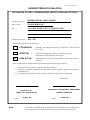
DECLARATION OF THESIS / UNDERGRADUATE PROJECT PAPER AND COPYRIGHT
Author’s full name :
MOHD RAZIF BIN ABDUL KADIR
Date of birth
:
23 DECEMBER 1987
Title
:
CONTROL DOOR LOCK SYSTEM VIA SMS
Academic Session:
2010 / 2011
I declare that this thesis is classified as :
CONFIDENTIAL
(Contains confidential information under the Official Secret
Act 1972)*
RESTRICTED
(Contains restricted information as specified by the
organisation where research was done)*
OPEN ACCESS
I agree that my thesis to be published as online open access
(full text)
I acknowledged that Universiti Teknologi Malaysia reserves the right as follows :
1. The thesis is the property of Universiti Teknologi Malaysia.
2. The Library of Universiti Teknologi Malaysia has the right to make copies for the purpose
of research only.
3. The Library has the right to make copies of the thesis for academic exchange.
Certified by :
SIGNATURE
871223-01-5757
PROFESSOR DR. RUZAIRI BIN HJ. ABDUL RAHIM
(NEW IC NO. /PASSPORT NO.)
NAME OF SUPERVISOR
06 MAY 2011
Date :
NOTES :
SIGNATURE OF SUPERVISOR
*
Date :
06 MAY 2011
If the thesis is CONFIDENTIAL or RESTRICTED, please attach with the letter from
the organisation with period and reasons for confidentiality or restriction.
i
“I hereby declare that I have read this thesis and in my opinion this thesis is
sufficient in terms of scope and quality for the award of the Bachelor of Engineering
( Electrical – Control & Instrumentation )
Signature
: ....................................................................................
DR . RUZAIRI BIN HJ. ABDUL RAHIM
Name of Supervisor : PROFESSOR
....................................................................................
Date
06 MAY 2011
: ....................................................................................
ii
CONTROL DOOR LOCK SYSTEM VIA SMS
MOHD RAZIF BIN ABDUL KADIR
Submitted to the Faculty of Electrical Engineering
in partial fulfillment of the requirement for the degree of
Bachelor of Engineering
(Electrical - Control & Instrumentation)
Faculty of Electrical Engineering
Universiti Teknologi Malaysia
MAY 2011
iii
“I declare that this thesis entitled “ Control Door Lock System Via SMS “ is the result
of my own research except as cited in the references. The thesis has not been
accepted for any degree and is not concurrently submitted in candidature of any other
degree.”
Signature
:
..............................................................
Name
:
MOHD RAZIF BIN ABDUL KADIR
Date
:
06 MAY 2011
iv
Dedicated, in thankful appreciation for
support, encouragement and understandings to
my beloved parents Abdul Kadir Bin Aula and Khadijah Binti Mohd Yunos,
my brother, Norazlan Bin Abdul Kadir,
Mohd Nazim Bin Abdul Kadir, Othman Bin Abdul Kadir,
and my sisters, Roziana Binti Abdul Kadir
Thanks for everything
v
ACKNOWLEDGEMENT
I would like to take this opportunity to express my deepest gratitude to my
project supervisor, Professor Dr. Ruzairi Bin Hj. Abd. Rahim who had presently
giving me guidance throughout the entire project. It would be have difficult to
complete this project without the guidance.
Thank you also to my family, my mom Khadijah Binti Mohd Yunos and my
dad Abdul Kadir Bin Aula who has given me support throughout my academic years.
Not forgetting their eternally moral support and understanding of my absent from
home while doing projects here which is far apart from home.
I would like to express my gratitude to Mr. Abdul Hadi Fikri Bin Abdul
Hamid who had been given me help technically and mentally during the process of
doing this project. It is to my advantage that I have received help and support from
him. Thank you for giving me technical advice to enhance my project. I give the
greatest thanks and honors for those that had supported me so far.
Thank you so much.
vi
ABSTRACT
GSM or better known as Global System Mobile is one of the mobile
communications wiring systems. GSM is a second generation digital cellular systems
that use circuit switching technology. GSM is basically designed to standardize the
mobile technology in Europe but has spread to the whole world. However, due to the
development of GSM technology is widespread use as International Roaming,
Mobile Internet, mobile fax, e-mails, Fax and Short Messaging System (SMS). SMS
usage among the world community led project control door lock system via SMS is
carried out. With the knowledge of GSM and also the concept of electronic review
this project will uses for the community and also use in the industrial sector.
vii
ABSTRAK
GSM atau lebih dikenali sebagai Global System Mobile adalah salah satu
sistem kabel komunikasi telefon. GSM merupakan kombinasi antara sistem khidmat
digital dan khidmat pesanan ringkas (SMS). GSM pada dasarnya direka bentuk
berdasarkan piawaian teknologi telefon di Eropah tetapi telah merebak ke seluruh
dunia. Namun begitu, perkembangan teknologi GSM telah digunakan secara meluas
sebagai Pengembaraan, telefon berinternet, faks melalui telefon, email, faks dan
SMS. Penggunaan SMS di kalangan masyarakat dunia dipimpin projek sistem
kawalan pintu di samping menggunakan SMS sebagai media penghantaran.
Berdasarkan pengetahuan tentang GSM dan juga konsep ulasan elektronik, maka
projek ini akan digunakan untuk masyarakat dan juga digunakan untuk sektor
industri.
viii
TABLE OF CONTENTS
CHAPTER
1
2
TITLE
PAGE
DECLARATION
iii
DEDICATION
iv
ACKNOWLEDGEMENT
v
ABSTRACT
vi
ABSTRAK
vii
TABLE OF CONTENTS
viii
LIST OF FIGURES
xi
LIST OF ABBREVIATIONS
xiii
LIST OF SYMBOLS
xiv
LIST OF APPENDICES
xv
INTRODUCTION
1
1.1
Background
1
1.2
Objective of Project
2
1.3
Scope of Project
3
1.4
Problem Statement
3
LITERATURE REVIEW
4
2.1
Company GSM
4
2.2
Description of Each Company
6
2.2.1 Witura Technology Sdn. Bhd.
6
2.2.1.1 Description About Hardware
7
ix
2.2.1.2 Installation WT-9001 IP65
9
2.2.1.3 Operation of Internal Circuit
12
2.2.1.4 Block Diagram Operation
15
2.2.1.5 Application of WT-9001 IP65
16
2.2.2 Probyte
3
2.2.2.1 Company Product
18
2.2.2.2 Specifications GSM Relay 2009
18
2.2.2.3 Block Diagram Operation
19
2.2.2.4 Circuit Operation
20
2.2.2.5 Application GSM Relay 2009
21
METHODOLOGY
22
3.1
Hardware Development
22
3.1.1 Block Diagram Operation System
23
3.1.2 Part of Hardware
23
3.2
4
17
3.1.2.1 Adapter AC to DC
24
3.1.2.2 GSM Modem
25
3.1.2.3 Voltage Regulator
27
3.1.2.4 Max 232 Serial Level Converter
28
3.1.2.5 Microcontroller ATMega32
30
3.1.2.6 Relay Driver and E.M Lock
32
Software Development
34
3.2.1 Initializing System
34
3.2.2 Security System
35
3.2.3 GSM System
37
RESULT & DISCUSSION
38
4.1
General Application System
38
4.1.1 Reset System
39
4.1.2 Lock Door System
39
4.1.3 Unlock Door System
40
4.1.4 Check Status Door
41
Application Security System
41
4.2.1 Warning Alert
42
4.2
x
5
4.2.2 Users
42
4.2.3 Password
43
4.2.4 Command
44
CONCLUSION
45
5.1
Conclusion
45
5.2
Project Problem
46
5.3
Recommendation and Suggestions
47
REFERENCES
49
Appendix A
50
Appendix B
51
Appendix C
58
xi
LIST OF FIGURES
FIGURE NO.
TITLE
PAGE
2.1
Comparison Between Two Companies GSM
6
2.2
GSM Remote Control WT-9001 IP5
7
2.3
Internal Design WT-9001 IP65
8
2.4
Installation diagram WT-9001 IP65
9
2.5
Antenna and Power Supply Connection
10
2.6
Schematic Diagram Screw Terminal Block
12
2.7
Schematic Diagram Digital Transistor Inputs
14
2.8
Schematic Diagram Opto-Isolated Inputs
15
2.9
Schematic Diagram MOSFET Outputs
15
2.10
Schematic Diagram Relay Outputs
16
2.11
Block Diagram Process of Witura Corp.
16
2.12
Simple Diagram GSM Relay 2009 Probyte
17
2.13
GSM Relay 2009 Probyte
18
2.14
Block Diagram Operation GSM-Relay 2009
19
2.15
Circuit Diagram GSM-Relay 2009 Probyte
20
3.1
Block diagram GSM Control Door Lock System
23
3.2
Basic Circuit for Adapter AC to DC Converter
24
3.3
Adapter AC to DC converter 12V and 9V
25
3.4
MLIS Modem Basic Terminal Block Diagram
26
3.5
MLIS GSM Modem
26
3.6
Circuit Diagram Voltage Regulator
27
xii
3.7
Voltage Regulator Circuit
28
3.8
Circuit Diagram Max 232 Serial Level Converter 29
3.9
Max 232 Serial Level Converter
29
3.10
Circuit Diagram Microcontroller ATMega32
31
3.11
Microcontroller ATMega32
31
3.12
Circuit Diagram Relay Driver ULN2803AG
33
3.13
Relay Driver ULN2803AG
33
3.14
Electromagnetic Lock
33
3.15
Flow Chart for Initializing System
35
3.16
Programming with command SMS
36
3.17
Flow Chart for Security System
36
3.18
Flow Chart for GSM System
37
4.1
Block Diagram Application Reset System
39
4.2
Block Diagram Application Lock Door System
40
4.3
Block Diagram Application Unlock Door System 40
4.4
Block Diagram Application Check Status Door
41
4.5
Block Diagram Security Warning Alert
42
4.6
Block Diagram Security Users
43
4.7
Block Diagram Security Password
43
4.8
Block Diagram Security Command
44
5.1
Product Control Door Lock System Via SMS
46
xiii
LIST OF ABBREVIATIONS
PC
-
Personel Computer
SMS
-
Short Messaging System
FKE
-
Fakulti Kejuruteraan Elektrik
GSM
-
Global System Mobile
IT
-
Information Technology
PWM
-
Pulse Width Modulation
LED
-
Light Emmiting Diode
TTL
-
Transistor-Transistor Logic
TLD
-
Therapeutic Target Database
CMOS
-
Complementary Metal Oxide Semiconductor
DTMF
-
Dual Tone Multi Frequency
IC
-
Intergrated Circuit
CPU
-
Central Processing Unit
HF
-
High Frequency
AC
-
Alternating Current
DC
-
Directing Current
IDE
-
Integrated Development Enviroment
ARM
-
Advance RSIC Machine
MIPS
-
Million Instruction per Second
E.M Lock
-
Electromagnetic Lock
xiv
LIST OF SYMBOLS
cm
-
centimeter
RPM
-
Revolutions Per Minute
mN.m
-
Newton Meter
MHz
-
Mega Hertz
xv
LIST OF APPENDICES
APPENDIX
TITLE
PAGE
A
Programming for “Initializing System”
50
B
Programming for “Security System”
51
C
Programming for “GSM System”
58
1
CHAPTER 1
INTRODUCTION
1.1
Background
The Global System for Mobile Communication (GSM) is the most popular
standard for mobile phone in the world. GSM service is used by over 2 billion people
across more than 212 countries and territories. Cell radius varies depending on antenna
height, antenna gain and propagation condition from a couple of hundred meters to a
several tens of kilometers. The growth in the internet industry is immense and along
with this trend wireless communication has rapidly gained wide acceptance, especially
the cellular system such as GSM . Mobile terminal will the major main machine
interface and not PC’s anymore. Mobile telephony, presently superseding wired
telephony, has become one of the most convenient information exchange tools since the
implementation of the GSM standard in the early 1990ies [1].
The Short Messages Services (SMS) in GSM allows amongst other the
transmissions of short text messages to mobile phones. In cases of an emergency the
2
SMS can be used to warn a large number of individual. SMS also can be used to control
the some system like a control the flood warning, control the water pumps and so on. To
control the system using SMS, GSM module and GSM remote control will be used.
A GSM remote control is a wonderful device which helps users control devices
remotely, no matter how far the distance they are from them. Anything from home
devices such as alarms, heating, air conditioning and so on, to commercial security
systems or IT equipment such as routers and server and the like can be remotely
controlled.
In essence, a GSM remote control is one of the most useful things out there. It is
able to be turned to any practical use. The unit sits on the mobile phone network and is
assigned a regular mobile number accordingly. Calling this number or even send a text
will engage the unit, thus giving control of the end device it is connected to.
The GSM remote control can be set up to only engage when received from
authorized numbers (secure control) or from any number across the world (open access
control). As such, any device can be controlled from anywhere. This opens up many
possibilities of course.
1.2
Objective of Project
The objective of the project is to design a locking system which is control by a
GSM (Global System Mobile) module. By doing that person in charge of locking the
3
door can unlock the door just by sending an SMS to GSM module. Generally, the design
of this system can help a person/supervisor to secure a building.
1.3
Scope of Project
Control door lock system via SMS is able to automate the system using:
1. Utilize a Global System Mobile (GSM) module to sent or received SMS from
user.
2. Uses a relay that is connected to electromagnetic lock to open and close door.
3. To uses a microcontroller Atmel ATmega32 to set a program and allow all
operation a function accordingly.
1.4
Problem Statement.
Criminal invasion of the home or office is often attributed to the attitude of the
negligence of the homeowner. Although a various security has been taken such as Finger
Print Based Door Lock System and Access Door Lock System using Keyword digital
door the problem of criminal still happened.
By using GSM Remote Control, the user can increase the security of the building
or residence from anywhere or anytime by only sending a message to device.
4
CHAPTER 2
LITERATURE REVIEW
GSM remote control is a tool that many produced in each country. Like the
United States, Japan, China, and Italy. But not all the product produced by each country
is similar. Results of the study, there were many differences in each GSM remote control
issued by the state. Differences can be seen in terms of the components used, operating
in each circuit are used, the chosen design, and also applications for each product. But
the concept of equality is the same. The concept is to control a system to send SMS and
change the data that is sent to the desired output.
2.1
Company GSM
From the results of the study, there are several manufacturers that produce
products GSM remote control. Referred to table 1 shows a list of companies. All of this
5
is the company known for its GSM remote control products. The study was conducted
for all companies in the world.
Table 2.1 : Company Manufacturer GSM Remote Control
No
Company Name
Product
Address
1.
DPS-Promatic srl.
TCX-EZGATE-PRO
47122 Forlì, Italy
2.
CrispTech
TCX-EZGATE-STD
GSM8000
4.
ElettroTERM S.r.l.
EL35.005
Via Villapizzone, 10
20156 Milano (MI)
5.
MERSYS Ltd.
GSM_A
23 Aizkraukles Str.
Riga LV-1006 Latvia
6.
Atmel .Inc
AVR-GSM
7.
Witura corporation
Sdn. Bhd.
WT-9001
8.
Probyte
GSM Relay 2008
2325 Orchard Parkway
San Jose, Ca 95131 United
States.
56-3A, Jalan PJU1/3B
SunwayMas Commercial Centre
47301 Petaling Jaya, Selangor,
Malaysia.
Nirvankatu 31, 33820 Tampere,
FINLAND
P.O. Box 468
Archerfield Qld 4108, Australia
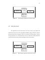
Referring to the table 1 , there are many companies that produce products GSM
remote control. In this chapter, the discussion is directed only to the two companies,
those companies Witura Corporation Sdn. Bhd and also companies Probyte. Comparison
between company Witura Corporation Sdn. Bhd. and Probyte is appropriate because
there are many differences between these two companies. This is because the operation
of the circuit, which is used for both components of the product and the functions of
each circuit, is different. The product from Witura Corporation Sdn. Bhd. have much in
common with other products such as products from Atmel company incorporation,
MERSYS Ltd. and also CrispTech Ltd. and not suitable for comparison.
6
Company
GSM
Witura
Technology
Sdn. Bhd.
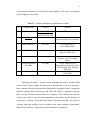
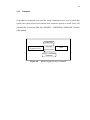
Figure 2.1
2.2
Probyte
Comparison Between Two Companies GSM Remote Control
Description of each company.
For this section will discuss the company's products have been selected for the
Witura Corporation Sdn. Bhd. and also Probyte. This discussion focuses on the
operation, a block diagram and operation of the circuit for the both of these products. In
addition, the application and use of the product will also be discussed in this section.
2.2.1
Witura Technology Sdn. Bhd.
Witura WT-9001 GSM remote control and GSM remote monitoring system
allow user to use your mobile phone to monitor and control your business from any
location. Its alarm facilities provide a flexible way to distribute critical alarm
information to any number of mobile phone users.
7
WT-9001 GSM Controller will send alerts and status directly to your mobile
phone and enable you to control simple applications at your remote site using text
messages from your mobile phone. You can switch on your pumps or read the current
dam level using your mobile phone while you are relaxing in a cafe bar or out on
business. Almost anywhere, anytime.
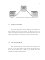
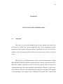
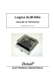
Figure 2.2
GSM Remote Control WT-9001 IP65
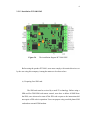
2.2.1.1 Description about Hardware
The WT 9001 GSM Controller module consists of the microprocessor, voltage
regulator, inputs and outputs drivers, relay, built-in GSM modem with SIM-card holder,
GSM antenna connector and connectors for external power supply and for input and
output signals from external equipment connection. The module includes one optoisolated and five non-isolated digital transistor inputs, one relay output and two
MOSFET transistor outputs [4].
8
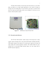
Figure 2.3
Internal Design WT-9001 IP65
Usually for users who want to use the product WT 9001, they need to understand the
connection depends on the company's manual provided. there are some connections that
need to be considered :
a) Screw terminal block for power supply connection (M1, M9)
b) Screw terminal blocks for Inputs and Outputs connection (M2...M8)
c) 2x8 pin header for analog inputs connection in analog version (P2)
d) 2x8 pin header used in special program version (P3)
e) SMA female connector for GSM antenna connection (P1)
There is also some indication to the user that should be taken out. This indicator
is useful for consumers to know the status of the device to operate properly. There are
two LED indicators on the device:
a) Red LED
b) Green LED
9
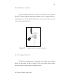
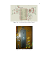
2.2.1.2 Installation WT-9001 IP65
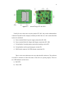
Figure 2.4
The installation diagram WT-9001 IP65
Before using the product WT-9001, users must comply with certain directives set
by the user using this company. Among the matters to be observed are:
a) Preparing for a SIM card.
The SIM card must be serviced by a small 3V technology. Before using a
SIM card for GSM SIM card remote control, users have to delete all SMS from
the SIM, users also need to turn off the PIN code request to the instructions did
not require a PIN code in operation. Users can prepare using a mobile phone SIM
card and an external GSM modem.
10
b) External device connection.
For power supply connection, users need to connect the screw terminal
block M1. Control output for connecting consumer devices to connect the screw
terminal block on the M6 to M8. GSM antenna connection and the user must
connect the antenna SMA in P1.
Figure 2.5
Antenna and Power Supply Connection.
c) Power Supply Connections
12VDC Power Supply must be connected with a stable screw terminal
block. Use only stable 1A min (2A peak) 12VDC power supply. Power supply
has put a negative voltage and over voltage protection.
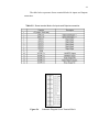
d) Input and Output Connections
11
The table below represents Screw terminal blocks for inputs and Outputs
connection:
Table 2.2 : Screw terminal blocks for Inputs and Outputs connection.
Figure 2.6
Schematic Diagram Screw Terminal Block
12
2.2.1.3 Operation of Internal Circuit.
a) Digital Transistor Inputs
The ULN2003A is monolithic high-voltage, high-current Darlington
transistor arrays. Each consists of seven NPN Darlington pairs that feature highvoltage outputs with common-cathode clamp diodes for switching inductive
loads. The collector-current rating of a single Darlington pair is 500mA.
The Darlington pairs may be paralleled for higher current capability.
Applications include relay drivers, hammer drivers, lamp drivers, display drivers
(LED and gas discharge), line drivers, and logic buffers. The ULN2003A has a
2.7kΩ _series base resistor for each Darlington pair for operation directly with
TTL or 5-V CMOS devices.
Figure 2.7
Schematic Diagram Digital Transistor Inputs
13
b) Opto-isolated Input.
The use of opto-isolated input is a switch operated. Operate to enable
TLP 181, the input must be between the range of 3V to 30V (Screw terminal
blocks M2, M3). If put in the opto-isolated voltage does not meet the prescribed
range, the TLP181 is not to operate. These applications can be seen more clearly
by further explanation. As an input to the Opto-Isolated reaches 3V TLP 181 will
operate and cause the transistor to send data to the microcontroller. Enter the
micro controller will receive a logic 1 (ON) if TLP181 operate and will receive a
logic 0 (OFF) if the input opto-Isolated input is less than 3V or greater than 30V
[3].
Figure 2.8
Schematic Diagram Opto-Isolated Inputs
c) MOSFET Outputs
MOSFETs are used both as discrete devices and as active elements in
digital and analog monolithic integrated circuits. in this circuit, MOSFETs
output should be connected to screw terminal blocks M6 and M7. MOSFET can
14
only operate at a range of not less than 20V. if the voltage applied to MOSFET
operates more than 20V will cause the faulty component.
Figure 2.9
Schematic Diagram MOSFET Outputs.
d) Relay Outputs
Microcontroller will send data in logic 1 or 0. When the transistor
receives the output logic 1 from the microcontroller, the transistor will operate in
accordance with the output voltage of the microcontroller. When the voltage on
the collector exceeds 0.7V, TSC112 relay will operate at 12V range and causes
the switch command (COM) contact with Normally Open (NO). Screw terminals
are connected to the relay blocks M7 and M8. These relays are only allowed to
operate at voltages between 12V to 24V only
Figure 2.10
Schematic Diagram Relay Outputs.
15
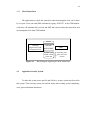
2.2.1.4 Block Diagram of Operation WT-9001 IP65
From the discussion that has been done before, a summary of operations for the
product WT-9001 is very easy. This circuit used is too complex and difficult for
consumers to understand the detailed operation of the circuit. To facilitate understanding
of the use of the product WT-9001, a block diagram is included below.
Transmitter
GSM Module
CPU Microcontroller
Relay Driver
Electromagnetic Lock
Figure 2.11
Block Diagram Process of Witura Corporation Sdn. Bhd.
Transmitter acts as a device to send the data entered. GSM module will receive
data sent by the transmitter and to change the analog data to digital data by the DTMF
decoder. The processed data will be sent to the CPU to the microcontroller and to
determine the output relay. Output relay driver depends on the output of CPU
microcontroller. Typically relay driver contain only IC which acts as a switch to the
relay. Electromagnetic lock will work depends on the output of the relay.
16
2.2.1.5 Application of WT-9001 IP65
WT 9001 is a versatile SMS alert device suited for most monitoring needs. it is a
device which able to sent a information or status of a system to multiple users. There are
many applications in the 9001 WT human life. This is because the safety of consumer
products is guaranteed when using this product. Applications that are often used by very
many users. From this study showed that there were two conditions that are often a lot of
applications used by consumers. Among these applications are:
a) Application at home automation:
Gate Access Control
Open Garage
Turn On Lights
Irrigation Control
Home security Monitoring
Turn On Kitchen Appliances
Turn On Air Conditioning
Turn On Heating System
b) Application at Industrial Automation.
Active Barrier Gate
Aquarium Monitoring
Machine Control
Fuel Water Tank Monitoring
Water Tank Monitoring And Pump Control
Fleet management System
Greenhouse Monitoring
Turn On Generator.
17
2.2.2
Probyte.
PROBYTE GSM-control is a real time and interactive GSM-control- and
measuring device, which allows user remotely control all the electrical appliances by a
standard home phone or by a GSM-phone using DTMF-tones. User can at same time
hear remote end. GSM relay is interactive for each pushbutton. The device has optional
four digits password, which prevents unauthorized persons to operate GSM control.
A new password can be changed remotely by a user. Adding commands to end of
phone number you can operate whole sequence without thinking whole process.
Separate commands from phone numbers by a special pause command.
Figure 2.12
Simple Diagram GSM Relay 2009 Probyte.
18
2.2.2.1 Company Product
The GSM-Relay 2009 is based on previous versions of Probyte GSM-relays.
They are used over ten years in tens of countries for tens of different purposes. A new
program of the GSM-Relay 2009 can install on old versions hardware (models 20072008). The new program is made into bigger processor. There is no need for separate
programs, control, thermostat and alarms are in the same CPU 2010 model. There are
many new alarms and controls. The basic command is simple: the relay 1 on command
is 011 and off the command 010. It can given locally, remotely or added to telephone
number with p (=pause) character.
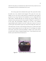
Figure 2.13 GSM Relay 2009 Probyte.
2.2.2.2 Specifications of GSM-Relay 2009
GSM-2010 relay is an interactive remote control to output 4 relay. In contrast to
WT-9001 uses only 2 relay output only. GSM-Relay 2009 can operate at voltages of
12VDC 500 mA. Controls carried out by the user by adding the command to terminate
19
the telephone number or by pressing a button on a GSM phone. Usually automatic, a
GSM modem can send DTMF-code using a separate PC or on a program that is
embedded in the microcontroller. GSM-relay unit has a connection hand free (HF) to be
connected to a Nokia phone with a 4 pin connector.
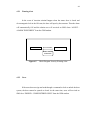
2.2.2.3 Block Diagram of Operation GSM-Relay 2009
From the discussion that has been done before, a summary of operations for the product
WT-9001 is very easy. This circuit used is too complex and difficult for consumers to
understand the detailed operation of the circuit. To facilitate understanding of the use of
the product WT-9001, a block diagram is included below.
Phone Transmitter
Phone Receiver
DTMF Decoder
CPU Microcontroller
Relay Driver
Electromagnetic Lock
Figure 2.14
Block Diagram Operation of GSM-Relay 2009 Probyte.
20
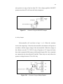
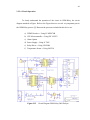
2.2.2.4 Circuit Operation
To clearly understand the operation of the circuit in GSM-Relay, the circuit
diagram attached at Figure. Refer to the Figure there are several very important part in
the GSM-Relay process [2]. Between the processes included in this device are:
a) DTMF Decoder = Using IC MT8870B
b) CPU Microcontroller = Using PIC 16F872
c) Alarm Option
d) Power Supply = Using IC 7805
e) Relay Driver = Using ULN2004
f) Temperature Sensor = Using LM335z
Figure 2.15
Circuit Diagram GSM-Relay 2009 Probyte
21
2.2.2.5 Application of GSM-Relay 2009
a) The remote controlled heating and remote controlled GSM-lock.
b) The heat control and door management of rented cottage for the owner
c) The remote control and alarm for grain drier for the farmers.
d) Pellet wood heater alarm
e) The remote control of car heating.
f) A door lock opens door for the service man even you are not at home.
22
CHAPTER 3
METHODOLOGY
In this section discussed how research is done in Chapter 2 can applied in this
system to control door lock system via SMS. There are two important part to be taken
into consideration to make this system will smooth operated. These part were be divided
in the hardware development and the software development. The further explanation for
the both of parts were be discussed in the below.
3.1
Hardware development.
Hardware development will be explain how to design concepts and circuits to be
made to control this system. normally, some things need to be considered as a way to
make the system more complex and also reduce the cost of making these systems. The
further information will be described in the below.
23
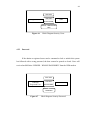
3.1.1
Block Diagram Control Door Lock System Via SMS.
Phone Transmitter
GSM Modem
Adapter AC to DC
12V
Adapter AC to DC
9V
Maxim Max 232
Microcontroller
ATMega32
Relay Driver
Relay
Electromagnetic
Lock
Figure 3.1
3.1.2
Part of Hardware
Block diagram GSM Control Door Lock System
24
There are several steps that should be taken in making any hardware in these
systems. This system must be related to the block diagram of the system. Further
information about the circuit and the equipment were be used will described in the
below.
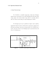
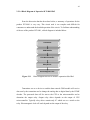
3.1.2.1 Adapter AC to DC
Adapter AC to DC converter is a powerful device can convert an analog current
to a direct current. This adapter usually uses a transformer to convert the voltage from
the wall outlet which the output voltage from the outlet is 240V analog current. This
adapter used to produce DC, a rectifier is used to convert alternating voltage to a
pulsating direct voltage, followed by a filter, comprising one more capacitors, resistors,
and sometimes inductors, to filter out (smooth) most of the pulsation. A small remaining
unwanted alternating voltage component at mains or twice mains power frequency is
unavoidably superimposed on the direct output voltage. For purposes such as charging
batteries the ripple is not a problem, and the simplest unregulated main powered DC
power supply circuit consists of a transformer driving a single diode in series with
a resistor.
Figure 3.2
Basic Circuit for Adapter AC to DC Converter.
25
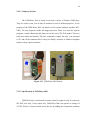
For this project, there are use two adapter converter. The input voltage for the
both adapter is 240V analog current and the outlet voltage for the each one is 12V and
9V. The adapter 12V used for supply voltage to the circuit and the other adapter 9V is
use for supply voltage to the GSM modem. The purpose used adapter 12V is to supply
energy to electromagnetic lock and for the circuit controller. While the adapter 9V is to
supplied energy to GSM Modem.
Figure 3.3
Adapter AC to DC converter 12V and 9V
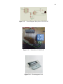
3.1.2.2 GSM Modem
A GSM modem is a specialized type of modem which accepts a SIM card, and
operates over a subscription to a mobile operator, just like a mobile phone. From the
mobile operator perspective, a GSM modem looks just like a mobile phone. When a
GSM modem is connected to a computer, this allows the computer to use the GSM
modem to communicate over the mobile network. While these GSM modems are most
frequently used to provide mobile internet connectivity, many of them can also be used
for sending and receiving SMS and MMS messages.
26
A GSM modem can be a dedicated modem device with a serial, USB or
Bluetooth connection, or it can be a mobile phone that provides GSM modem
capabilities. For the complete this project, GSM/GPRS Terminal Modem MLIS were
chosen. The MLIS modem is a compact size and robust Tri-Band GSM/GPRS terminal
designed for industrial use. It also has the TCP/IP stack in-built to support different
internet services. Therefore, it can be deployed easily in plug and play M2M and many
other applications.
Figure 3.4
MLIS Modem Basic Terminal Block Diagram
Figure 3.5
MLIS GSM Modem
27
3.1.2.3 Voltage Regulator
A voltage regulator is an electrical regulator designed to automatically maintain a
constant voltage level. A voltage regulator may be a simple "feed-forward" design or
may include negative feedback control loops. It may use electromechanical mechanism,
or electronic components. Depending on the design, it may be used to regulate one or
more AC or DC voltages. For this project, four voltage regulators were used to avoid
each voltage regulator from continuously heat. Each voltage regulator has a serial
number, which is 7812, 7809, 7806 and 7805. The input voltage of voltage regulator
circuit is 12V direct current that supply from the adapter. This voltage regulator circuit
was reducing the voltage from 12V to 5V [5].
Figure 3.6
Circuit Diagram Voltage Regulator
28
Figure 3.7
Voltage Regulator Circuit
3.1.2.4 Max 232 Serial Level Converter
Almost all digital devices which used require either Transistor-Transistor Logic
(TTL) logic levels. Therefore the first step to connecting a device to the RS-232 port is
to transform the RS-232 levels back into 0 and 5 Volts. When these voltages have
already covered, this is done by RS-232 Level Converters. Two common RS-232 Level
Converters are the 1488 RS-232 Driver and the 1489 RS-232 Receiver. Each package
contains 4 inverters of the one type, either Drivers or Receivers. The driver requires two
supply rails, +7.5 to +15v and -7.5 to -15v. As user could imagine this may pose a
problem in many instances where only a single supply of +5V is present. However the
advantages of these I.C's are they are cheap.
Another device is the MAX-232. It includes a Charge Pump, which generates
+10V and -10V from a single 5v supply. This I.C. also includes two receivers and two
transmitters in the same package. This is handy in many cases when user only want to
use the Transmit and Receive data Lines. Don't need to use two chips, one for the
receive line and one for transmit. However all this convenience comes at a price, but
29
compared with the price of designing a new power supply it is very cheap. There are
also many variations of these devices. The large values of capacitors are not only bulky,
but also expensive. Therefore other devices are available which use smaller capacitors
and even some with inbuilt capacitors. However the MAX-232 is the most common.
Figure 3.8
Circuit Diagram Max 232 Serial Level Converter
Figure 3.9
Max 232 Serial Level Converter
30
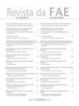
3.1.2.5 Microcontroller ATMega32
There
are
numerous
choices
for
microcontrollers.
In
this
project,
microcontrollers ATMega32 series made by Atmel were chosen. The Atmel chips can be
easily programmed. User can write code in the higher level C, instead of assembly
language. The ATMega32 series have more Pulse-width modulation (PWM) channels,
memory, Analog Digital Converters (ADC) channels, and Input-Output (I/O) lines than
most other chips. The ATMega32 has 16 Million Instruction per second (MIPS) of
processing power and 32 KB of flash. It has 4 PWM channels sufficient for us since user
only needed one for the main motor controller.
Besides that, ATMega32 including in AVR family. AVR family has a GCC
based IDE that is free for the whole range of their processors. From smallest to biggest,
one code to rule them all. AVR is an 8-bit CPU and on the same clock it is 4 times faster
than 8-bit PIC and 12 times faster than 8051. ARM is 32-bit, more powerful and much
more power hungry. It will eat battery quickly while AVR will run for weeks or months.
They are not in the same range, and not used for the same tasks. It would be like
comparing 4GHz quad core biennium PC to small ARM that runs your mobile phone
[6].
31
Figure 3.10
Circuit Diagram Microcontroller ATMega32
Figure 3.11
Microcontroller ATMega32
32
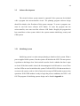
3.1.2.6 Relay Driver and Electromagnetic Lock
Relay Driver ULN2803AG was used to control the output of electromagnetic
lock. The ULN2803AG is a small integrated circuit that contains 8 transistor driver
channels. Each channel has an input to a resistor connected to the base of a transistor and
a 1 amp open collector output capable of handling up to about 30volts (if my memory is
correct). Each of the collectors has a reverse biased diode connected to a common Vcc
pin that provides inductive spike protection.
Typical uses are for micro-processor interfaces to relays, lamps, solenoids and
small motors. A ULN2803AG with a set of relays is a simple and effective way of
switching mains voltages for example. They are used less commonly today but were
once an almost universal means of interfacing processors to power devices.
While an electromagnetic lock is a locking device that locking door depending
on the output of relay driver. This consists of an electromagnet and armature plate. By
attaching the electromagnet to the door frame and the armature plate to the door,
a current passing through the electromagnet attracts the armature plate holding the door
shut. Unlike an electric strike a magnetic lock has no interconnecting parts and is
therefore not suitable for high security applications because it is possible to bypass the
lock by disrupting the power supply. Nevertheless, the strength of today's magnetic
locks compares well with that of conventional door locks and they cost less
than conventional light bulbs to operate. Power supplies incorporating a trickle-charged
lead-acid battery pack can be used to retain security for short-term power outages [7].
33
Figure 3.12
Circuit Diagram Relay Driver ULN2803AG
Figure 3.13
Figure 3.14
Relay Driver ULN2803AG
Electromagnetic Lock
34
3.2
Software Development
The circuit for these system cannot be operated if the system not be included
with a program into microcontroller circuit. The planning program software design
should be related to the flowchart of this system concepts. To create a program, user
must be used the bases software AVR Studio. To enter the program into the
microcontroller, users must used the software AVR Studio. Roughly the program that
has created have a three system which is the system contains initializing, security and
GSM system.
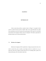
3.2.1
Initializing System
Initializing system is a main concept planning to launch a whole system. When a
power supplied in this systems, first the system will initialize the LED. The next process
is perform to checking a door. Limit switch is used to check a whether the door is open
or closed. If the limit swith is closed, the electromagnetic lock ON and vice versa. There
are four LEDs are used to initialize this system. If all the LED’s ON that mean there is
an error to the system, such as a lack of network coverage at GSM modem to proceed an
operations. If the GSM modem is ready to begin the process conditions, the LED 1 will
ON. The program of initializing systems design can be found in Appendix A.
35
OPEN
SUCCESS
Figure 3.15
3.2.2
CLOSE
FAIL
Flow Chart for Initializing System
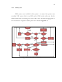
Security System
To make the system safer and more effective, security system included in the program.
Roughly, the overall systems was controlled by the one user which is admin user. To
used the system, user (any number of SIM-card) should be registered into the
microcontroller program. Maximum user is 65 number. There are some security
situations were taken like a warning alert in case invasion criminal happened and send a
wrong command or password. Users will received a warning for any errors made on this
systems. Program system security can be found in Appendix B.
36
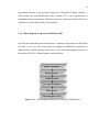
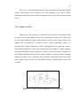
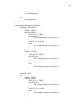
#include "app.h"
#define MAX_USER 5
uint8_t admin[12]
="+60147748841";
uint8_t* notify = admin;
uint8_t USER_ID = 0;
uint8_t cmdStat[6]
="STATUS";
uint8_t cmdRst[5]
="RESET";
uint8_t cmdLock[4]
="LOCK"; //LOCK 4-digit-password
uint8_t cmdUnlock[6]="UNLOCK"; //UNLOCK 4-digit-password
uint8_tuser[MAX_USER][12]={"+60137879814","+60147748841","xxxxxxxxxxxx”,"xxxxxxxxxxxx","};
uint8_t pass[MAX_USER][4] ={"1234","5757","xxxx","xxxx",};
uint8_t secAlert[22]
= "ALERT-ALARM TRIGGERED!";
uint8_t secRstErr[22] = "ERROR-RESET THE SYSTEM";
uint8_t secAdmin[20] = "DENIED-CONTACT ADMIN";
uint8_t secUnregUser[24]= "DENIED-UNREGISTERED USER";
uint8_t secWrongPass[21]= "DENIED-WRONG PASSWORD";
uint8_t secUnknown[22] = "DENIED-UNKNOWN COMMAND";
uint8_t secLockPend[16]= "QUEUED-DOOR OPEN";
uint8_t msg1[]="ALARM=TRIGGERED\r\nDOOR=OPEN\r\nLOCK=ON";
uint8_t msg2[]="ALARM=TRIGGERED\r\nDOOR=OPEN\r\nLOCK=OFF";
uint8_t msg3[]="ALARM=TRIGGERED\r\nDOOR=CLOSE\r\nLOCK=ON";
uint8_t msg4[]="ALARM=TRIGGERED\r\nDOOR=CLOSE\r\nLOCK=OFF";
uint8_t msg5[]="ALARM=IDLE\r\nDOOR=OPEN\r\nLOCK=ON";
uint8_t msg6[]="ALARM=IDLE\r\nDOOR=OPEN\r\nLOCK=OFF";
uint8_t msg7[]="ALARM=IDLE\r\nDOOR=CLOSE\r\nLOCK=ON";
uint8_t msg8[]="ALARM=IDLE\r\nDOOR=CLOSE\r\nLOCK=OFF";
Figure 3.16
Programming with command SMS
OFF
OPEN
CLOSE
TRUE
ON
OFF
FALSE
Figure 3.17 Flow Chart for Security System
ON
37
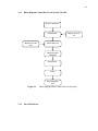
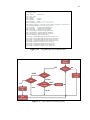
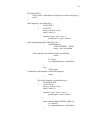
3.2.3
GSM System
GSM system were included in this system is to ensure that systems runs
smoothly. GSM system check every SMS send to GSM modem and ensure that the
GSM transmit status or warning to the users with a more consistent and appropriate in
the circumstances. Program for GSM system can be found in Appendix C.
Figure 3.18 Flow Chart for GSM System
38
CHAPTER 4
RESULT & DISCUSSION
Form the study carried out by the hardware and software systems, this system
can be controlled. From the operation of this system, there are several different
applications. these applications include a general application system and the security
system. More information further is described in the next section.
4.1
General Application System.
For the general applications system is include ways consumers user this system.
These applications was included how to open and lock the door, reset the system and
also check a status of the door for the moment using SMS. For the more information
further is described below.
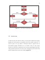
39
4.1.1
Reset System
The application reset system is to be used when to start and stop the alarm
security. There is one user as an admin user to sent this command. Admin will sent an
SMS command with typing “RESET” and sent to the GSM modem. Once the system
already reset, at the same time user will receive an SMS from the GSM modem concern
on the status of electromagnetic lock at that moment.
RESET
Sent SMS
Admin
GSM
Received SMS
ALARM = IDLE
DOOR = OPEN
LOCK = OFF
Figure 4.1
4.1.2
Depending on
the status door at
the moment
Block Diagram Application Reset System
Lock Door System
For the application to lock the door can only be done by the admin and registered
users only. Users (admin & registered users) can send SMS command by typing
“LOCK” and followed by a password that has been designated “XXXX” to the GSM
modem. The door will automatically lock and the user will received SMS from GSM
modem about the status of door and electromagnetic lock.
40
LOCK XXXX
Admin &
Registered User
Sent SMS
GSM
Received SMS
ALARM = IDLE
DOOR = CLOSE
LOCK = ON
Figure 4.2
4.1.3
Block Diagram Application Lock Door System
Unlock Door System
The application for the locked doors can only be done by the admin and
registered users only. Users can be send SMS command y typing “UNLOCK” followed
by password that can be designated “XXXX” and send to the GSM modem. The door
will open and this user will automatically received an SMS from GSM modem that
concern about the status doors and electromagnetic lock for that moment.
UNLOCK XXXX
Admin &
Registered User
Sent SMS
GSM
Received SMS
ALARM = IDLE
DOOR = CLOSE
LOCK = ON
Figure 4.3
Block Diagram Application Unlock Door System
41
4.1.4
Check Status Door
The applications to check the status door and electromagnetic lock can be done
by everyone. Users can send SMS command by typing “STATUS” to the GSM modem.
each users will automatically received and SMS that concern about the status door and
electromagnetic lock from GSM modem.
STATUS
Admin &
Registered User&
Unregistered User
Sent SMS
ALARM = IDLE
DOOR = CLOSE
LOCK = ON
Figure 4.4
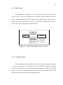
4.2
GSM
Received SMS
Depending on the
status door at the
moment
Block Diagram Application Check Status Door
Application Security System
To make this system more specific and effective, security system has be used in
this system. These security system was include safety alert warning system comprising,
users, password and the instruction.
42
4.2.1
Warning Alert
In the event of invasion criminal happen when the status door is closed and
electromagnetic lock in the ON state, the door will open by the someone. Then the alarm
will automatically ON and the admin user will received an SMS alerts “ALERT –
ALARM TRIGGERED!” from the GSM modem.
Admin
Received SMS
GSM
ALERT – ALARM
TRIGGERED!
Figure 4.5
4.2.2
Block Diagram Security Warning Alert
Users
If the users does not sign and send through a command to lock or unlock the door
system, the door cannot be opened or closed. At the same time, users will received an
SMS alert “DENIED – UNREGISTERED USER” from the GSM modem.
43
LOCK XXXX
Sent SMS
Unregistered User
GSM
Received SMS
DENIED – UNREGISTERED
USER
Figure 4.6
4.2.3
Block Diagram Security Users
Password
If the admin or registered users send a command to lock or unlock this system
but followed with a wrong password, the door cannot be opened or closed. Users will
received an SMS alert “DENIED – WRONG PASSWORD” from the GSM modem.
LOCK XXXX
Admin &
Registered User
Sent SMS
GSM
Received SMS
DENIED – WRONG
PASSWORD
Figure 4.7
Block Diagram Security Password
44
4.2.4
Command
If the admin or registered users send the wrong command to reset, lock or unlock this
system, the system will not reset and the door cannot be opened or closed. Users will
automatically received an SMS alert “DENIED – UNKNOWN COMMAND” from the
GSM modem.
CLOSED XXXX
Admin &
Registered User
Sent SMS
GSM
Received SMS
DENIED – UNKNOWN
COMMAND
Figure 4.8
Block Diagram Security Command
45
CHAPTER 5
CONCLUSION & RECOMMENDATION
5.1
Conclusion.
This project was successful introduced base on the concepts that control door
lock system via SMS. This concepts application base on the combination concepts
product from the company Probyte and Witura Corporation. After the survey from the
product of the both company already finish, the concepts of this system were able to
create.
This system is using GSM modem as a main to received and transmitted a signal
SMS through the SIM-card number of registered users. Once the registered user sent a
SMS that contained command to unlock or lock door system, GSM will received a
command and send to the signal through a microcontroller ATMega32. At this stage,
microcontroller ATMega32 will conform that the command is matching with a program
or not depending on the program code. ATMega32 will generate these command and
46
send to the relay driver to activated the relay control. Once the relay control active, the
electromagnetic lock ON to closed the door and vice versa.
The security system also be included in this system. This system able to inform
the admin users if any criminal invasion happened. This system also secure some
building. In case if user send a wrong password or command, this system cannot be
proceed to the next stage. Then this users immediately received a warning SMS from
GSM modem. Command SMS that were send from users must be different to any
situations to make system operated. For microcontroller ATMega32 is a powerful device
in this system. This microcontroller ATMega32 were be able to save maximum
registered number until 65 number for one time. So that mean as many as 65 users can
uses this system. Seems like this system can be used in the meeting room, faculty class,
office and etcetera. So for the overall conclusion of this project, to make the successful
system of control automatic door lock via SMS, there is a lot of things to be consider
such as these system able to protect that building or residence, able to easily used by
user and be able to inform or responded through a users.. If one of them does not work
then the system cannot follow the instructions set.
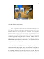
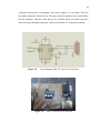
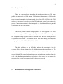
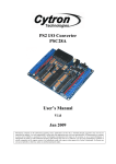
Figure 5.1
Product Control Door Lock System Via SMS
47
5.2
Project Problem
There are some problems in making the hardware architecture. The main
problem encountered is the GSM antenna. GSM antenna is the last part on GSM modem
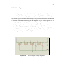
to received and transmitted signal from outside. Green light LED will flash at the GSM
modem with an interval 5 seconds means the GSM modem in standby-by to continue the
process. Connection to antenna is often interrupted. So, should the cable end is punched
a little further into the GSM antenna.
The second problem is about voltage regulator. The input supplied is 12V want
to reduce the voltage until 5V for support a get logic circuit. For the first time using only
two component voltage regulator which is 7809 and 7805. But after running this both
component become heated. This problem can be settle after adding two component
voltage regulator which is 7812, 7809, 7806 and 7805.
The third problems are the difficulties to burn the programming into the
controller. This is because the problem of cable that interface the controller to pc. The
cable is too sensitive and to burn the cable it is need to hold the cable until the burn
process finished. The second problems that occurs during the same problems from the
cable is the data that transmit and received during the burn process is not same, so the
process need to try until the transmit signal be the same as received.
5.3
Recommendation and Suggestion of future Work
48
There are some recommendations and suggestions that can be apply in order to
improve the automatic door lock system via SMS. Among method to improve this
system is using door restrictor to automatically closed when someone open the door. For
the example, in this case, if registered user sent an SMS to closed the door (ON
electromagnetic lock) but moment that the door still open GSM will reply "QUEUEDDOOR OPEN". That mean the door must closed first to lock the electromagnetic lock.
So, applied restrictor door in this system can ensure the door automatically closed.
For the second suggestion is using back-up battery 12V. In case, when present in
situation electrical shutdown, this system cannot operate because there are not have
power supplied. The purpose install back-up battery in this system is to ensure this
system operate in several hour when power supplied shutdown.
49
REFERENCES
1.
Mouton, A.J.J. and Smith, G.E., Effective remote control of electric
motors using GSM technology; IEEE; 2009, Page(s): 1 - 7
2.
Xingang Guo and Yu Song ; Design of automatic weather station based
on GSM module; IEEE; 2010; Page(s): 80 – 82
3.
Zai Shyong Kwah, GSM Based Remote Control Terminal Unit of The
Flood Warning and Control System; University of Bradford; January 2006
4.
GSM Remote monitor and Remote Control system; Witura Corporation
Sdn. Bhd.; 2009
5.
Ying-Cheng Wu and Chun-Yueh Huang; A Low Dropout Voltage
Regulator with Programmable Output. Department of Electronics
Engineering, National University of Tainan, Taiwan; 2010.
6.
Relay Driver; “Micro-Controller 8051: data acquisition and control
system”; at http://microcontroller51.blogspot.com
7.
Jack R. Smith. RS232 converter interface; Programming the PIC
Microcontroller with MBASIC; IEEE; 2007; Page(s) : 151-186.
50
APPENDIX A
Programming for “Initializing System”
#include "app.h"
int main(){
SYSTEM_init();
SYSTEM_run();
return 0;
}
void SYSTEM_init(void){
LEDS_init();
SEC_init();
GSM_init();
}
void SYSTEM_run(void){
while(1){
SEC_check();
}
}
void GSM_initDone(error_t isErr){
if(isErr!=SUCCESS){
LEDS_set(ALL_ON);
}
else{
LEDS_on(1);
}
}
51
APPENDIX B
Programming for “Security System”
#include "app.h"
#define MAX_USER 5
uint8_t admin[12]
="+60147748841";
uint8_t* notify = admin;
uint8_t USER_ID = 0;
uint8_t cmdStat[6] ="STATUS";
uint8_t cmdRst[5] ="RESET";
uint8_t cmdLock[4] ="LOCK";
//LOCK 4-digit-password
uint8_t cmdUnlock[6]="UNLOCK";//UNLOCK 4-digit-password
uint8_tuser[MAX_USER][12]={"+60137879814","+60147748841","xxxxxxxxxxxx”,"x
xxxxxxxxxxx","xxxxxxxxxxxx"};
uint8_t pass[MAX_USER][4] ={"1234","5757","xxxx","xxxx","xxxx",};
uint8_t secAlert[22]
= "ALERT-ALARM TRIGGERED!";
uint8_t secRstErr[22]
= "ERROR-RESET THE SYSTEM";
uint8_t secAdmin[20]
= "DENIED-CONTACT ADMIN";
uint8_t secUnregUser[24] = "DENIED-UNREGISTERED USER";
uint8_t secWrongPass[21] = "DENIED-WRONG PASSWORD";
uint8_t secUnknown[22]
= "DENIED-UNKNOWN COMMAND";
uint8_t secLockPend[16]
= "QUEUED-DOOR OPEN";
uint8_t msg1[]="ALARM=TRIGGERED\r\nDOOR=OPEN\r\nLOCK=ON";
uint8_t msg2[]="ALARM=TRIGGERED\r\nDOOR=OPEN\r\nLOCK=OFF";
uint8_t msg3[]="ALARM=TRIGGERED\r\nDOOR=CLOSE\r\nLOCK=ON";
uint8_t msg4[]="ALARM=TRIGGERED\r\nDOOR=CLOSE\r\nLOCK=OFF";
52
uint8_t msg5[]="ALARM=IDLE\r\nDOOR=OPEN\r\nLOCK=ON";
uint8_t msg6[]="ALARM=IDLE\r\nDOOR=OPEN\r\nLOCK=OFF";
uint8_t msg7[]="ALARM=IDLE\r\nDOOR=CLOSE\r\nLOCK=ON";
uint8_t msg8[]="ALARM=IDLE\r\nDOOR=CLOSE\r\nLOCK=OFF";
/*
BOOL ALARM = FALSE;
BOOL LOCK_ON = FALSE;
BOOL LOCK_PENDING = FALSE;
BOOL DOOR_OPEN = FALSE;
/*
void sec_lock(void);
void sec_unlock(void);
void sec_updateStatus(uint8_t* hpNum);
void sec_adminRight(sms_t* sms);
void sec_userRight(sms_t* sms);
BOOL isDoorOpen(void);
void SEC_init(void){
SET_BIT(DDRD,DDD3);
//set PD3 as output (relay control)
SET_BIT(PORTC,PC0);
//set pull up for limit switch (NC)
if(isDoorOpen()){
sec_unlock();
CLR_BIT(DDRC,DDC0);
}
else{
sec_lock();
}
//check the door
//initialize the door lock state - unlock/door open
//set PC0 as input (limit switch)pen
//initialize the door lock state - lock/door close
}
void SEC_check(void){
isDoorOpen();
if(!ALARM){
if(DOOR_OPEN && LOCK_ON){
ALARM = TRUE;
GSM_tx(admin,secAlert,sizeof(secAlert));
}
else if(!DOOR_OPEN && LOCK_PENDING){
sec_lock();
//Update Sender
53
sec_updateStatus(notify);
}
}
else{
LEDS_toggle(4);
_delay_ms(300);
}
}
BOOL isDoorOpen(void){
DOOR_OPEN = READ_BIT(PINC,PC0);
return DOOR_OPEN;
}
void sec_lock(void){
LOCK_PENDING = FALSE;
SET_BIT(PORTD,PD3);
LOCK_ON = TRUE;
}
void sec_unlock(void){
CLR_BIT(PORTD,PD3);
LOCK_ON = FALSE;
}
/*
*
*/
void GSM_txDone(error_t err){
if(err!=SUCCESS){
LEDS_toggle(1);
LEDS_toggle(2);
}
else{
LEDS_toggle(2);
}
}
void GSM_rx(sms_t* sms){
LEDS_toggle(3);
if(txtComp(sms->txt,cmdStat,6)){
sec_updateStatus(sms->senderNum);
return;
}
54
if(ALARM){
sec_adminRight(sms);
}
else{
sec_userRight(sms);
}
}
void sec_updateStatus(uint8_t* hpNum){
//ALARM = TRIGGERED
if(ALARM){
//DOOR = OPEN
if(DOOR_OPEN){
//LOCK_ON = TRUE
if(LOCK_ON){
GSM_tx(hpNum,msg1,sizeof(msg1)-1);
}
//LOCK_ON = FALSE
else{
GSM_tx(hpNum,msg2,sizeof(msg2)-1);
}
}
//DOOR = CLOSE
else{
//LOCK_ON = TRUE
if(LOCK_ON){
GSM_tx(hpNum,msg3,sizeof(msg3)-1);
}
//LOCK_ON = FALSE
else{
GSM_tx(hpNum,msg4,sizeof(msg4)-1);
}
}
}
//ALARM = IDLE
else{
//DOOR = OPEN
if(DOOR_OPEN){
//LOCK_ON = TRUE
if(LOCK_ON){
GSM_tx(hpNum,msg5,sizeof(msg5)-1);
}
//LOCK_ON = FALSE
else{
GSM_tx(hpNum,msg6,sizeof(msg6)-1);
}
}
55
//DOOR = CLOSE
else{
//LOCK_ON = TRUE
if(LOCK_ON){
GSM_tx(hpNum,msg7,sizeof(msg7)-1);
}
//LOCK_ON = FALSE
else{
GSM_tx(hpNum,msg8,sizeof(msg8)-1);
}
}
}
}
void sec_adminRight(sms_t* sms){
if(txtComp(!sms->senderNum,admin,12)){
GSM_tx(sms->senderNum,secAdmin,sizeof(secAdmin));
return;
}
if(txtComp(sms->txt,cmdRst,5)){
ALARM = FALSE;
LEDS_off(4);
if(isDoorOpen()){
sec_unlock();
}
else{
sec_lock();
}
}
else{
GSM_tx(sms->senderNum,secRstErr,sizeof(secRstErr));
return;
}
sec_updateStatus(sms->senderNum);
}
void sec_userRight(sms_t* sms){
BOOL USER_EXIST = FALSE;
for(uint8_t userID=0;userID<MAX_USER;userID++){
if(txtComp(sms->senderNum,&user[userID][0],12)){
USER_EXIST = TRUE;
USER_ID = userID;
break;
}
56
}
if(!USER_EXIST){
GSM_tx(sms >senderNum,secUnregUser,sizeof(secUnregUser));
return;
}
if(txtComp(sms->txt,cmdLock,4)){
//
LOCK XXXX
//
012345678
uint8_t pswrd[4]="xxxx";
uint8_t count = 0;
for(uint8_t cnt=5; cnt<9; cnt++){
pswrd[count++]=sms->txt[cnt];
}
if(txtComp(pswrd,&pass[USER_ID][0],4)){
if(isDoorOpen()){
LOCK_PENDING = TRUE;
notify = sms->senderNum;
GSM_tx(notify,secLockPend,sizeof(secLockPend));
return;
}
sec_lock();
sec_updateStatus(sms->senderNum);
}
else{
GSM_tx(sms
>senderNum,secWrongPass,sizeof(secWrongPass));
return;
}
}
else if(txtComp(sms->txt,cmdUnlock,6)){
//
UNLOCK XXXX
//
012345678910
uint8_t pswrd[4]="xxxx";
uint8_t count = 0;
for(uint8_t cnt=7; cnt<11; cnt++){
pswrd[count++]=sms->txt[cnt];
}
if(txtComp(pswrd,&pass[USER_ID][0],4)){
sec_unlock();
sec_updateStatus(sms->senderNum);
}
57
else{
GSM_tx(sms
>senderNum,secWrongPass,sizeof(secWrongPass));
return;
}
}
else{
GSM_tx(sms>senderNum,secUnknown,sizeof(secUnknown));
}
}
58
APPENDIX C
Programming for “GSM System”
#include "app.h"
uint8_t* tmpTxt;
uint8_t tmpTxtLen = 0;
/***********************************************************************
* ENUMERATIONS
***********************************************************************/
enum{
GSM_INIT = 0x21,
GSM_RX,
GSM_TX,
TX_CURSOR,
TX_COUNTER,
TX_ACK,
RX_AVAIL,
RX_READ,
TXT_STATUS,
TXT_SENDER,
TXT_TOD,
TXT_TXT,
TXT_ACK,
59
SMS_DEL,
};
uint8_t GSM_STATE;
uint8_t TX_STATE;
uint8_t RX_STATE;
uint8_t RX_TXT;
/***********************************************************************
* STRING LIST
***********************************************************************/
uint8_t okTxt[2] = "OK";
uint8_t cmti[5]="+CMTI";
uint8_t txtStat[10]="REC UNREAD";
/***********************************************************************
* AT COMMAND LIST
***********************************************************************/
uint8_t newSmsAlert[11]
="AT+CNMI=1,1";
uint8_t setTxtFormat[9]
="AT+CMGF=1";
uint8_t sendTxt[8]
="AT+CMGS=";
uint8_t readReq[8]
="AT+CMGR=";
uint8_t atDelSMS[8]
="AT+CMGD=";
uint8_t crlf[2]={0x0D,0x0A};
/***********************************************************************/
/***********************************************************************
* PRIVATE VARIABLES
***********************************************************************/
uint8_t rxAtAck[3];
uint8_t atTxCount[20];
uint8_t atRxInd[20];
uint8_t txtStatus[10];
uint8_t rxCount = 0;
BOOL MARKER = FALSE;
BOOL STARTED = FALSE;
/***********************************************************************
* PRIVATE FUNCTIONS PROTOTYPE
***********************************************************************/
void gsm_sendAt(uint8_t* atCmd,uint8_t len);
void gsm_rxAtAck(uint8_t data);
void gsm_atResponse(error_t err);
void gsm_txTxt();
void gsm_rxTxCounter(uint8_t data);
void gsm_rxTxInd(uint8_t data);
void gsm_rxTxt(uint8_t data);
60
void gsm_txtDel(uint8_t index);
/***********************************************************************/
/***********************************************************************
* APPLICATION PROGRAMMING INTERFACE
***********************************************************************/
void GSM_init(void){
GSM_STATE = GSM_INIT;
TX_STATE = TX_CURSOR;
RX_STATE = RX_AVAIL;
RX_TXT = TXT_STATUS;
USART_init();
ENABLE_INTERRUPTS();
gsm_sendAt(newSmsAlert,sizeof(newSmsAlert));
}
void GSM_tx(uint8_t* hp,uint8_t* sms,uint8_t len){
_delay_ms(2500);
GSM_STATE = GSM_TX;
TX_STATE = TX_CURSOR;
tmpTxt = sms;
tmpTxtLen = len;
USART_txStream(sendTxt,sizeof(sendTxt));
USART_txByte('\"');
USART_txStream(hp,12);
USART_txByte('\"');
USART_txStream(crlf,2);
}
void USART_rx(uint8_t data){
switch(GSM_STATE){
case GSM_INIT:
gsm_rxAtAck(data);
break;
case GSM_TX:
switch(TX_STATE){
case TX_CURSOR:
if(data=='>'){
TX_STATE = TX_COUNTER;
gsm_txTxt();
}
break;
case TX_COUNTER:
gsm_rxTxCounter(data);
61
break;
case TX_ACK:
gsm_rxAtAck(data);
break;
}
break;
case GSM_RX:
switch(RX_STATE){
case RX_AVAIL:
gsm_rxTxInd(data);
break;
case RX_READ:
gsm_rxTxt(data);
break;
}
break;
case SMS_DEL:
gsm_rxAtAck(data);
break;
}
}
/***********************************************************************/
/***********************************************************************
* PRIVATE FUNCTIONS PROTOTYPE
***********************************************************************/
void gsm_sendAt(uint8_t* atCmd,uint8_t len){
USART_txStream(atCmd,len);
USART_txStream(crlf,2);
}
void gsm_txTxt(void){
USART_txStream(tmpTxt,tmpTxtLen);
USART_txByte(0x1A);
}
void gsm_txRdReq(void){
RX_STATE = RX_READ;
USART_txStream(readReq,sizeof(readReq));
USART_txByte(newSMS.index);
USART_txStream(crlf,2);
}
/***********************************************************************/
void gsm_rxAtAck(uint8_t data){
if(data==0x0A && !MARKER){
MARKER = TRUE;
rxCount = 0;
}
62
else if(data==0x0A && MARKER){
MARKER = FALSE;
if(txtComp(rxAtAck,okTxt,2)){
gsm_atResponse(SUCCESS);
}
else{
gsm_atResponse(FAIL);
}
rxCount = 0;
}
else if(MARKER){
rxAtAck[rxCount++] = data;
}
}
void gsm_atResponse(error_t isErr){
switch(GSM_STATE){
case GSM_INIT:
if(isErr!=SUCCESS){
GSM_initDone(FAIL);
return;
}
if(!STARTED){
STARTED = TRUE;
gsm_sendAt(setTxtFormat,sizeof(setTxtFormat));
}
else{
STARTED = FALSE;
GSM_STATE = GSM_RX;
GSM_initDone(SUCCESS);
}
break;
case GSM_TX:
GSM_STATE = GSM_RX;
TX_STATE = TX_CURSOR;
RX_STATE = RX_AVAIL;
GSM_txDone(isErr);
break;
case SMS_DEL:
if(isErr!=SUCCESS){
GSM_STATE = GSM_RX;
return;
}
if(txtComp(txtStatus,txtStat,10)){
newSMS.status = UNREAD;
}
else{
newSMS.status = READ;
63
}
GSM_STATE = GSM_RX;
GSM_rx(&newSMS);
break;
}
}
void gsm_rxTxCounter(uint8_t data){
if(data==0x0A && !MARKER){
MARKER = TRUE;
rxCount = 0;
}
else if(data==0x0A && MARKER){
MARKER = FALSE;
TX_STATE = TX_ACK;
rxCount = 0;
}
else if(MARKER){
atTxCount[rxCount++] = data;
}
}
void gsm_rxTxInd(uint8_t data){
if(data==0x0A && !MARKER){
MARKER = TRUE;
rxCount = 0;
}
else if(data==0x0A && MARKER){
MARKER = FALSE;
if(!txtComp(atRxInd,cmti,5)){
TX_STATE = TX_CURSOR;
GSM_STATE = GSM_RX;
RX_STATE = RX_AVAIL;
GSM_txDone(FAIL);
return;
}
if(atRxInd[12]>'9'){
TX_STATE = TX_CURSOR;
GSM_STATE = GSM_RX;
RX_STATE = RX_AVAIL;
GSM_txDone(FAIL);
}
newSMS.index = atRxInd[12];
gsm_txRdReq();
rxCount = 0;
}
else if(MARKER){
atRxInd[rxCount++] = data;
}
64
}
void gsm_rxTxt(uint8_t data){
switch(RX_TXT){
case TXT_STATUS:
if(data==0x22 && !MARKER){
MARKER = TRUE;
rxCount = 0;
}
else if(data==0x22 && MARKER){
MARKER = FALSE;
rxCount = 0;
RX_TXT = TXT_SENDER;
}
else if(MARKER){
txtStatus[rxCount++] = data;
}
break;
case TXT_SENDER:
if(data==0x22 && !MARKER){
MARKER = TRUE;
rxCount = 0;
}
else if(data==0x22 && MARKER){
MARKER = FALSE;
rxCount = 0;
//done
RX_TXT = TXT_TOD;
}
else if(MARKER){
newSMS.senderNum[rxCount++] = data;
}
break;
case TXT_TOD:
if(data==0x22 && !MARKER){
MARKER = TRUE;
rxCount = 0;
}
else if(data==0x22 && MARKER){
MARKER = FALSE;
rxCount = 0;
//done
RX_TXT = TXT_TXT;
}
else if(MARKER){
newSMS.tod[rxCount++] = data;
}
break;
case TXT_TXT:
65
if(data==0x0A && !MARKER){
MARKER = TRUE;
rxCount = 0;
}
else if(data==0x0A && MARKER){
MARKER = FALSE;
newSMS.smsLen = rxCount;
rxCount = 0;
//done
RX_TXT = TXT_ACK;
}
else if(MARKER){
newSMS.txt[rxCount++] = data;
}
break;
case TXT_ACK:
if(data==0x0A && !MARKER){
MARKER = TRUE;
rxCount = 0;
}
else if(data==0x0A && MARKER){
MARKER = FALSE;
rxCount = 0;
if(txtComp(rxAtAck,okTxt,2)){
RX_TXT = TXT_STATUS;
RX_STATE = RX_AVAIL;
gsm_txtDel(newSMS.index);
break;
}
else{
RX_TXT = TXT_STATUS;
RX_STATE = RX_AVAIL;
}
}
else if(MARKER){
rxAtAck[rxCount++] = data;
}
break;
}
}
void gsm_txtDel(uint8_t index){
GSM_STATE = SMS_DEL;
USART_txStream(atDelSMS,sizeof(atDelSMS));
USART_txByte(index);
USART_txStream(crlf,2);
}
/***********************************************************************/
66
BOOL txtComp(uint8_t* txt1,uint8_t* txt2,uint8_t len){
for(uint8_t i=0;i<len;i++ ){
if(txt1[i]!=txt2[i]){
return FALSE;
}
}
return TRUE;