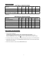
1
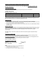
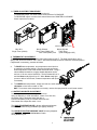
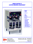
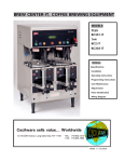
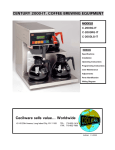
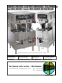
BREW CENTER, COFFEE BREWING EQUIPMENT
TWIN:
BC2, BC302
SINGLE:
BC1, BC301, BC120, BC240
BC-2E
BC-1E
BREWERS SHOWN WITH OPTIONAL STAINLESS STEEL FUNNEL
MANUAL
* Specifications
* Start up procedure
* Adjustments
* Parts Identification
* Installation
* Operating Instructions
* Care Maintenance
* Wiring Diagram
Cecilware sells value... Worldwide
43 -05 20th Avenue, Long Island City, NY 11105
TEL: 718-932-1414
FAX: 718-932-7860
N831A-C 4/3/2002
SPECIFICATIONS
ELECTRICAL SPECIFICATIONS
MODEL NO.
Volts
Watts
BC1
BC301
BC120
BC240
BC2
BC302
120/240
4100
120/240
4100
120
1800
240
3120
120/240
6200
120/240
6280
Amps
18
18
15
13
27
27
Wall Outlet (Receptacle)
6-20R
6-20R
5-15R
6-15R
6-30R
6-30R
Power Cord CE202 – 30A optional
All Brew Centers are single phase with 3 wires plus a ground with cord and plug, except Eport 220V, 1 PH,
(UROPEAN).
MECHANICAL SPECIFICATIONS
MODEL NO.
BC1
BC301
BC120
BC240
BC2
BC302
Tank Capacity (US gal.)
3.1
3.1
3.1
3.1
6.2
6.2
1 x 36
12/24/36
12/24
12 x 24
2 x 36
(2x)12/24/36
Cups/Hour
240
240
240
200
400
400
Height (includes 4” legs)
Width (+ 2”for ¼"water connection)
Depth
31
9¼
17 ½
31
9¼
17 ½
31
9¼
17 ½
31
9¼
17 ½
31
18
17 ½
31
18
17 ½
65
65
65
65
105
105
Cups/Brew Cycle
Ship Weight lbs.
FAST START-UP PROCEDURE
1.
Turn on power to the Brewer.
The Brewer will automatically start filling. After 6 minutes the filling cycle will stop.
Allow approximately 20 minutes for the brewer to reach full brewing temperature (197'-203').
When the GREEN READY LIGHT comes ON the brewer is ready to brew the next batch of coffee.
2. Turn Warmer Switch to the ON position. The Warmer Switches also double as CYCLE STOP switches.
3. Place coffee in the Funnel. See “COFFEE BREWING INSTRUCTIONS” for the recommended amount.
Place funnel in the machine.
4. With Funnel and Carrier in place activate GREEN BREW switch.
2
INSTALLATION AND OPERATING INSTRUCTIONS
Warranty is void if the Brewer is connected to any Voltage other than the Voltage specified on the
data label of the Brewer.
UNPACKING AND INSPECTION
Carefully unpack the Brewer by cutting the straps and lifting the carton off the Brewer.
ASSEMBLY AND SET-UP
The Brewer is shipped complete with:
DESCRIPTION
Adjustable legs
Carriers complete with Faucets and Covers
Funnels with sample Filter pack
BC1, 301, 120, 240
4
1
1
BC2, 302
4
2
2
Remove carriers from Brewer, one has the four (4) legs packed inside. Install legs by tilting Brewer on its
back and screwing the legs into the threaded leg supports on bottom.
WATER HOOK UP
The National Sanitation Foundation (NSF) requires the following for NSF approved installation:
1. A quick disconnect water connection or enough extra coiled tubing (at least 2x the depth of the unit) so
that the Brewer can be moved for cleaning underneath.
2. An approved flow-back prevention device such as a double check valve to be installed between Brewer
and water supply.
WATER CONNECTION
The Brewer comes equipped with a ¼ inch compression water inlet fitting located in the back. Use a ¼ inch
copper tubing to connect the Brewer to a cold water supply. Water pressure should be: 20 PSI min. to 90
PSI max. An external shut-off valve and a water filtering system with a charcoal filter are highly
recommended.
Turn water supply on and check for leaks at the water inlet connections, tighten compression fitting if
necessary.
ELECTRICAL CONNECTIONS
A terminal block inside the base compartment is provided for electrical connections. Opening for field
conduit connections are provided in the bottom and the back of the base.
To access the Terminal Block, loosen the 2 screws on the side of the base cover. Disengage base cover
from rear panel by lifting base cover up and lifting back towards rear panel.
Power Cord CE202 – Optional ?
RECOMMENDED WIRING SIZES
Model No.
Single: BC1, BC301, BC120, BC240
Twin: BC2, BC302
Single (1) Phase
12 AWG
10 AWG
Note:
1. Neutral (N) and Ground Wires to be 14 AWG Minimum.
2. Field wiring must be suitable for 75º C.
3. Use Copper wire only for all power supply connections.
3
INITIAL PRIMING – Filling of Tank
The BC Brewers are shipped with the Thermostat in the OFF position. Do not turn Thermostat to the ON
position until the Brewer has been fully primed.
a. Turn water supply on and check for leaks at the water inlet connections. Tighten compression fitting if
necessary.
b. Turn on power to the Brewer. The Brewer will automatically start filling. After 6 minutes the filling cycle will
stop and the thermostat should be turned clockwise to the full ON position. Allow approximately 20 minutes for
the brewer to reach full brewing temperature (197'-203').
When the GREEN READY LIGHT comes ON the brewer is ready to brew the next batch of coffee.
NOTE: Before proceeding further, make sure the sample Filter pack has been removed from the
funnel.
CHECKING BREW CYCLE OUTPUTS.
The BC-Series brewers are factory preset to deliver the proper amount of brewing water for the 12 cup,
24 cup and 36 cup brew cycles. Nevertheless, it is a good practice to check the output levels prior to
brewing the first batch of coffee.
BC1 and BC2: Full 36 cups (3 decanters) per brew cycle with a 20% by-pass.
BC120 and BC240: Selectively 12 cups (1 decanter) or 24 cups (2 decanters) per brew cycle.
No by-Pass.
BC301 and BC302: Selectively 12, 24 and 36 cups per brew cycle with a 20% by-pass for the 36 cup
cycle only.
TO START A BREW CYCLE:
Turn Warmer Switch to the ON position. The Warmer Switches also double as CYCLE STOP switches.
With Funnel and Carrier in place activate GREEN BREW switch.
On BC120, BC240, BC301 and BC302 brewers first activate brew switches marked 12 cups and then
check output. Do the same with the 24 cup brew switch and the 36 cup brew switch for the BC301 and
BC302 units.
NOTE: 12 cups equal 1 full decanter.
If necessary adjust the timer(s) to increase or decrease output levels. See Timer adjustments.
COFFEE BREWING INSTRUCTIONS
Place filter paper into brew basket and add finely ground coffee as per chart below:
MODEL#
Single
Single
Single
Twin
Single
Twin
BC120
BC240
BC1
BC2
BC301
BC302
CUPS BREWED
12 / 24 Cups
12 / 24 Cups
36 Cups
2 x 36 Cups
12 / 24 / 36 Cups
2 x (12 / 24 / 36 Cups)
RECOMMENDED COFFEE
AMOUNT
2 oz./ 4 oz.
2 oz./ 4 oz.
6 oz.
2 x 6 oz.
2 oz./ 4 oz./ 6 oz.
2x (2 oz./ 4 oz./ 6 oz.)
TOTAL BREW TIME
3.0 / 4.5 Minutes
3.0 / 4.5 Minutes
6.0 Minutes
6.0 Minutes
3.0 / 4.5 / 6.0 Minutes
2x (3.0 / 4.5 / 6.0 Minutes)
Insert brew funnel back into brewer and position empty carriers under brew funnels. With Warmer
Switches on (lit), depress Green Brew Switches. Total brew time will vary according to cups selected.
After funnel stops dripping, remove and empty funnels.
Warning: Remove Brew funnel ONLY after it has stopped dripping.
4
ADJUSTMENTS
1. BY-PASS FLOW VALVE ADJUSTMENTS
Depending on the model number, the BC Brewers have been factory set to brew 12, 24 and/or 36 cups of
coffee, with the BY-PASS adjusted for a 20% BY-PASS flow of brewing water for the 36 cup, brew output
only. Since water hardness, the brand of coffee, and the length of brew time are important factors in final
drink taste, it may be necessary to adjust the percentage of BY-PASS. In general, the more ground
coffee used for each brew, the higher the percentage of BY-PASS. Proceed as follows to adjust BYPASS:
Place empty carrier without cover under brew funnel.
a. Pull brew funnel out 3 inches, exposing BY-PASS outlet behind funnel.
b. Activate warmer/cycle stop switch. Switch will be lit.
c.
Hold measuring cup under BY-PASS outlet and activate Green Brew Switch.
After 15 seconds, push warmer/cycle stop switch to stop cycle.
d. Measure ounces of water in cup and ounces of water in carrier. Divide ounces in cup by total volume
dispensed (add ounces in cup and carrier) to get the BY-PASS ratio.
e. To get more BY-PASS, turn slotted adjustment screw in spray-head adjuster Counter-ClockWise.
Turning adjuster screw clockwise will decrease the BY-PASS flow. See figure below.
NOTE: The BY-PASS valve is activated only when the 36 cup cycle is selected.
The BC301 and BC302 units do not use the BY-PASS when brewing for 12 and 24 cups.
The BC120 and BC240 models only brew for 12 or 24 cups and therefore do not have the BY-PASS.
DUAL BYPASS VALVE
ADJUSTMENT
SCREW [2]
5
2. TIMER ADJUSTMENT PROCEDURE
Remove the top cover to access the brew timer(s).
To INCREASE output: turn timer knob a small increment CLOCKWISE.
To DECREASE output: turn timer knob a small increment COUNTER-CLOCKWISE.
Check output level in carrier.
REMOVE JUMPER FOR 240V
BCI, BC2
Single Timer (L264A)
BC120, BC240
BC301, BC302
Dual Timer (58026) 120
Triple Timer
Dual Timer (58027) 240
(Dual Voltage)(L410C)
3. THERMOSTAT ADJUSTMENT
The BC Brewers are factory set to deliver hot brewing water at 200' F. The water temperature, at the
spray head, should be between 195' F-203' F with the thermostat knob at its maximum clockwise position.
If adjustment is necessary, proceed as follows:
a.
To RAISE water temperature, turn temperature control knob to
its maximum clockwise position. Remove the knob and locate
slotted adjustment screw inside hollow thermostat shaft. Using a
narrow-bladed screwdriver, engage slotted adjustment screw
and turn it 1/4 turn counter-clockwise. The thermostat will cut in
and the Green ready light will go off. When Green ready light
comes on after a few minutes, measure temperature and repeat
if necessary.
b. To LOWER water temperature, simply turn knob one notch counterclockwise to next lower number on dial.
HINT: To measure water temperature accurately, remove the spray-head for a solid water stream.
4. WATER FLOW RATE ADJUSTMENT
Locate adjustment screw on valve (as show here).
Using an Allen Key or a flat screwdriver, rotate ¼ turn at a time,
Clockwise (CW) to decrease water flow rate or
Counter-Clockwise (CCW) to increase water flow rate.
Check water flow output after each ¼ turn.
The SINGLE DISPENSE VALVE is factory adjusted to dispense
0.6 oz./sec. of water during the brew cycle (spray duration).
The DOUBLE/ DILUTION DISPENSE VALVE is factory adjusted,
on both sides, to dispense 0.22 oz./sec of water
during dilution cycle.
6
SPECIAL COMPONENTS TEST
1) CHECK DISPENSE VALVES FOR LIME BUILD-UP (Located inside top cabin)
Drain the water tank to just below the level of the Dispense Valves.
Remove the Valves and clean. You can take these valves apart by
hand as shown.
Replace the assembly as needed.
Replace the valve into the tank and refill tank.
2) WATER INLET VALVE (SOLENOID) TEST (Located inside bottom cabin)
Turn power off. If the water level rises inside the tank, and shoots out of
the overflow, the Water Inlet Valve is leaking. Disconnect wires from the
Water Inlet Valve coil and connect a 2 wire line cord to the terminals. Plug
it into a 115V outlet. If water flows in and stops when you pull it out, the
Valve is working fine. Repeat this test a few times. The problem may be
in the Probe. If the water does not flow in when the cord is plugged into
an electrical outlet, the Solenoid coil may be damaged, opened or the
valve may have an obstruction preventing the water from flowing in.
Clean or replace it.
A Check Valve is installed to prevent backflow.
To check proper function of Check Valve, disconnect water line from
the Check Valve, check for dripping from the disconnected end of the
Check Valve. If it leaks, replace it.
Water inlet Valve max. flow rate is 1.3 gal/min.
3) WATER LEVEL PROBE TEST (Located on tank top, inside top cabin)
If there is a lack of water, you will get an uneven flow.
Check the probe as follows:
Turn on the power and water supply. Check inside the tank to make
sure the water is not touching the Probe. Pull the wire and terminal out
of the Probe rod. If water starts flowing into the tank, the Probe may
be grounded, due to excessive liming. Check with Ohm meter. Clean
or replace.
4) SOLID STATE WATER LEVEL CONTROL BOARD
TO PROBE
N
LI TO SOLENOID
a) Make sure there is power input to the board at the terminals 2 & 3. Your
voltmeter should read 115 volts. It should read the same at terminals 1
& 3. This is the output power to electrify the coil of the solenoid valve to
open it. The lack of voltage at terminals 2 & 4 will indicate that the
water level board is not working properly.
b) Make sure all wire connections to the board are tight.
c) The grounding plate at the top, in the back of the board, should be
securely grounded. The board will not work, or will work erratically, if it
is not grounded properly. If after this, the board is still failing to open
the water inlet valve, then replace it.
GROUNDING PLATE IN
BACK OF THE BOARD
L398A - 120V
L399A - 240V
GROUND TERMINAL
7
TROUBLESHOOTING GUIDE
WARNING: To reduce the risk of electrical shock unplug the dispenser power cord before repairing or replacing any internal
components of the unit.. Before any attempt to replace a component be sure to check all electrical connections for proper
contact
PROBLEM
PROBABLE CAUSE
REMEDY
1.
No power to the
machine.
a) Loose wire connection.
b) Blown fuse.
c) Tripped Breaker
a) Check wire connections to Power Switch.
b) Check fuse.
c) Re-set Breaker
2.
Machine keeps
repeating cycle.
a) Dispense Switch defective.
a) Replace Dispense Switch.
3.
Water does not
shut off. Water
keeps running into
funnel.
3.
Water will not
stop flowing into
tank.
a) Leaking Water Inlet Valve [Solenoid].
a) Clean/check fittings of Valve. Replace Valve if needed.
See ”Water Inlet Valve Test”
b) Check Switch connections. Replace it if needed.
c) Clean Dispense Valve. Replace Dispense Valve if inoperative.
a) Water Level Probe malfunction.
b) Water Inlet Valve malfunction..
a) Check Probe. Replace if necessary. See “Probe Test”
b) Check Solenoid. Replace if necessary. See “Water Inlet Valve
Test”
4.
Water drips from
brew funnel.
a) Leaking Dispense Valve.
b) Too much water in tank.
c) Spray Head Fitting is clogged.
d) Water Valve blocked by scales.
a) Replace Water Dispense Valve.
b) Dispense some water from tank.
c) Clean Spray Head Fitting.
d) Replace or clean Valve Seat.
5.
No water is going
into tank at all.
a) Water Inlet Valve (Solenoid) malfunction.
b) Water Level Probe malfunction.
a) Check Water Inlet Valve. Replace if necessary.
See “Water Inlet Valve Test”
b) Check Probe. Replace if necessary. See “Probe Test”.
6.
Water is not
heating up in the
water tank.
7.
Cold coffee.
a) Temperature setting is incorrect.
b) Loose connection to Heating Element.
c) Heater is burned out or defective.
a) Set Temperature at 200°F – See Thermostat Adjustments.
b) Make sure all wires are tight.
c) Replace the Heater.
a) Run out of hot water in tank.
b) Temperature setting is incorrect.
c) Loose electrical connection.
d) Bad or burnt out Heating Element.
a) Allow time for water in tank to heat after filling.
b) Set temperature at 200°F. (See Thermostat Adjustments)
c) Check all electrical connections for contact.
d) Replace Heater.
8.
Coffee too strong.
a) Water flow too low.
b) Too much coffee in the brew funnel.
a) Adjust water flow rate on Dispense Valve.
b) Put the proper amount of coffee in funnel. See suggested amount.
9.
Coffee too weak.
a) Not enough coffee in the brew funnel.
b) Water flow too high.
a) Add coffee.
b) Adjust water flow rate on Dispense Valve.
b) Inoperative Switches.
c) Clogged Dispense Valve
8
CLEANING AND SANITIZING
SANITIZING:
All food dispensing units should be sanitized periodically. All parts to be sanitized must be cleaned first.
To prepare a sanitizing solution:
ADD 2 TSP. OF LIQUID CLOROX BLEACH (5.25% CONCENTRATION) TO 1 GALLON OF WATER AT
ROOM TEMPERATURE (70°- 90°F).
Note: Always start with a unopened bottle of Clorox Bleach since the solution from an opened bottle has a
short life span.
• Soak all parts for a minimum of 3 min. in the sanitizing solution.
• Let all sanitized parts drain and dry naturally. DO NOT WIPE THEM DRY.
• Before using the sanitized unit (or parts) with food stuffs, rinse all parts thoroughly with water.
Water pipe connecting and fixtures directly connected to a potable water supply shall be sized, installed, and
maintained in accordance with Federal, Sate, and Local codes (section 7).
TO PREVENT CORROSION DAMAGE:
1. Carrier liners should be cleaned daily.
2. Use only neutral pH cleansers such as dish washing detergents to clean the unit. Do not use cleansers
containing alkalies, acids or harsh abrasives.
3. Use mild abrasive nylon or brass brushes for removing coffee deposits. Do not use steel wool, wire
brushes or other abrasive tools that will scratch the stainless steel surface.
4. Use recommended sanitizing solutions.
5. Let the unit dry naturally after sanitizing. Do not wipe them. Do not use the unit until completely dry.
DRAINING OF WATER TANK:
Fast draining of tank is possible by Drain Hose which is located behind the front panel and held in place by a
clamp to the side wall.
When draining of tank is required, always disconnect power supply and turn thermostat counterclockwise to the
OFF position.
CLEANING:
1. Wipe all exterior surfaces of the unit with a soft, damp cloth using warm water and mild detergent.
WARNING: Before attempting to clean the Warmer Deck, make sure the Warmer switches are "OFF"
and the Warmer Deck has cooled down to room temperature.
2. Clean all interior surfaces, in contact with the substance dispensed, thoroughly.
Caked-on residue may have to be soaked before removal. On metal or glass surfaces, stiff bristle brushes
may be used.
3. Rinse the cleaned unit thoroughly with warm water and let dry.
4. Empty contents from brew funnel, wash and let dry (use a mild dishwasher detergent).
CARE OF STAINLESS STEEL:
Stainless steel surfaces that come in contact with food substances must be cleaned every day. Many food
products contain acid, alkalies, salt and other substances that corrode the stainless steel. In order to prevent
the corrosion of the material, proper cleaning, and sanitizing must be performed.
When cleaning the stainless steel, only neutral pH cleansers are to be used. Highly acidic or alkaline cleansing
agents and chlorinating sanitizing solutions cause corrosion.
DELIMING OF TANK:
Minerals in water also cause corrosion if they are allowed to accumulate. Therefore, the interior walls should
be cleaned frequently in order to remove mineral deposits and prevent corrosion from occurring.
WARNING: Do not immerse Carrier into water or use in dishwasher.
9
PARTS IDENTIFICATION
[* RECOMMENDED SPARE PARTS]
SINGLE UNITS TWIN UNITS
BC1, BC301, BC2, BC302
BC120, BC240
ITEM P/N QTY P/N QTY
DESCRIPTION
1 SF26A 1 SB49A 1 CABINET TOP COVER
2
-------- SWITCH PANEL LABELS:
N829A 1
---- BC120 & BC240
N892A 1 N815A 1 BC1 / BC2
N822A 1 N823A 1 BC301 / BC302
5* L155A 2 L155A 2 BC2 ON-OFF SWITCH
L155A 1 L155A 1 BC120 ON-OFF SWITCH
L155A 1 L155A 1 BC240 ON-OFF SWITCH
L155A 1 L155A 1 BC1 ON-OFF SWITCH
6* L383A 2 L383A
BC120 BREW SWITCHES
L383A 1
….
BC1 BREW SWITCHES
L383A 2
….
BC240 BREW SWITCHES
L383A 3
….
BC301 BREW SWITCHES
L383A
L383A 2 BC2 BREW SWITCES
L383A
L383A 6 BC302 BREW SWITCHES
7* L389A 1 L389A 1 POWER SWITCH
8* DO67A 1 D067A 2 FAUCET, HOT WATER -plastic
9 SF74Q 1 SC81Q 1 TANK WELDMENT ASS’Y
10* V210Q 1 V210Q 2 FUNNEL ASS'Y, BLACK
11* R615A 1 SC86A 1 BASE WARMER COVER
12* G108A 1 G108A 2 WARMER ELEMENT
13* M090A 2 M090A 4 GROMMET F/HEAT SHIELD
14 U485A 1 U485A 2 HEAT SHIELD
15
16
17*
18
19
*
20*
SF27A
M172S
L069A
K331A
C396A
C395A
CE202
SF28A
1
1
1
1
1
1
1
1
SB65Q
M172S
L069A
K331A
C396A
C395A
CE202
SB66A
1
2
3
4
5
6
7
8
9
10
11
12
13
14
15
16
1
1
1
1
1
CABINET FRAME ASS'Y
LEGS [SET OF 4]
POWER SWITCH - MAIN
ELBOW FITTING, IN. VALVE
FUSE HOLDER
FUSE
1 POWER CORD 30A-OPTIONAL
1 FRONT COVER–NOT SHOWN
17
18
19
20
10
BC302 FRONT OPEN VIEW
TOP CABIN OPEN VIEW
1
2
1
3
1
4
1
5
1
6
7
1
1
1
8
1
9
1
TOP CABIN - PARTS IDENTIFICATION
[* RECOMMENDED SPARE PARTS]
ITEM SPARE SINGLE UNITS TWIN UNITS
PARTS P/N
QTY P/N
QTY
1
2
*
*
3
*
4
5
6
7
8*
9
10
11
12
13
14
15
16
17
18
*
*
*
*
*
*
*
*
*
*
*
*
*
L656A
L499A
M532A
G367A
G369A
G286A
K683A
M483A
L688A
L689A
L264A
58026
L410A
B177A
SD06Q
K671Q
M197A
E107A
K668A
M483A
M483A
M483A
L681A
K402Q
P465A
RK70A
1
1
1
1
1
1
1
1
1
1
1
1
1
1
1
1
1
1
1
1
1
1
1
1
L656A
L499A
M523A
G367A
G369A
G286A
K683A
M483A
L688A
L689A
L264A
---L410A
B177A
SD06Q
K671Q
M197A
E107A
K668A
M483A
M483A
M483A
L681A
K402Q
P465A
SC82A
1
1
1
2
1
2
2
1
2
1
2
1
2
2
2
2
2
2
2
1
1
1
1
1
DESCRIPTION
HI-LIMIT
FLOAT SENSOR WITH
RUBBER GASKET
HEATER (1.7 KW 120V) OR
HEATER (3.0 KW 230V) OR
HEATER (4.0 KW 230V)
OVERFLOW FITTING FTB
SILICONE HOSE- OVERFLOW ( .312”ID x 7”L)
DINSPENSE VALVE, SINGLE
120V 60HZ
DINSPENSE VALVE, DUAL, BYPASS 120V 60HZ
SINGLE TIMER - 120V
DUAL TIMER - 120V [ or 58027 – 220V ]
TRIPLE TIMER - 120V
CONTACTOR – 2 POLE, 30/40 Amp, 120V [B178A FOR 208/240V]
SPRAY HEAD BASE ASS’Y
SPRAY HEAD FITTING ASS’Y WITH
RUBER WASHER
SPRAY HEAD
NUT
SILICONE HOSE - SPRAY HEAD ( .312”ID x 11”L)
SILICONE HOSE- BYPASS ( .312”ID x 6”L)
SILICONE HOSE – HOT WATER FAUCET (.312”ID x 10.5”L)
THERMOSTAT
HI-LEVEL CONTROL SENSOR
SCREW, ¼-20 x 5/8
TANK TOP
11
BOTTOM CABIN OPEN VIEW
1
5
4
3
2
BOTTOM CABIN - PARTS IDENTIFICATION
[* RECOMMENDED SPARE PARTS]
BC2-IT
BC302-IT
SPARE
BC301-IT
PARTS
ITEM
1
2
3
4
5
*
*
*
*
P/N
QTY
P/N
L069A
B083A
CD257
C396A
C395A
CE202
CG99A
1
1
1
1
1
1
L069A
B083A
CD257
C396A
C395A
CE202
CG99A
QT
Y
1
1
1
1
1
1
12
DESCRIPTION
POWER SWITCH
TERMINAL BLOCK
WATER INLET VALVE
FUSE HOLDER
FUSE
POWER CORD 120/240V or
POWER CORD 240V
CARRIER ASS’Y
1
2
3
4
5
6
7
14
CARRIER ASS’Y 97208
Item
1
2
2
3
4
5
6
7
8
9
10
11
12
13
14
[* RECOMMENDED SPARE PARTS]
Description
Part #
*
Handle, black 3”
02015
*
Hold Down Bracket
U833A
*
Thumb Screw
M299A
*
Carrier Cover S.S.
U811A
*
Gasket, Cover Carrier
M294A
Label
NG47A
Screw
P808A
*
Faucet Guard
U812A
*
Faucet & Shank Ass’y 8”
99461
*
Faucet Washer
7227
*
Faucet Hex Nut
03067
*
Washer, Base
38318
*
Sight Gauge Shield
38316
*
Sight Gauge Glass
38315
*
Washer, End Cap
38317
*
End Cap
38314
13
12
8
9
11
10
FAUCET & SHANK ASS’Y 99461
13
BC-1E
120/240
3 WIRES + GROUND
3100 WATTS 14A
60Hz
REFILL CIRCUIT
BREW CIRCUIT
PROBE
N
L1
LOAD
L
BREW VALVE
1 PH
W R B
FAUCET & SHANK ASS’Y 99461
BLK
HI LIMIT
RED
BLK
GND
L1
FUSE 6 AMP.
N
RED
BLACK
WHITE
D
L2
C.G.
C.G.
-
D
14
BC120E 2 WIRES+GRD 1800W 15A 1PH
BC240E 2 WIRES+GRD 3120W 13A 1PH
BREW INDICATOR LIGHT
PROBE
N
L1
LOAD
12 CUP
24 CUP
L2 S L1 SW2 SW3 I2 I1
FLOAT SWITCH
BLK
WARMER
HI LIMIT
BC-120E DUAL BREWTIME
BC-240E DUAL BREWTIME
BLK
GND
L1
FUSE 6 AMP.
N
RED
BLACK
WHITE
A
C.G.
C.G.
-
A
15
BC-301E 120/240 3 WIRES+GND 4140W 18A 1PH 60HZ
REFILL CIRCUIT
BREW CIRCUIT
PROBE
N
L1
LOAD
12 24 36
11
8
INLET VALVE
9 10
BLK
HI LIMIT
RED
BLK
BC-301E TRIPLE BREW TIME
GND
BLK
L1
FUSE 6 AMP.
N
L2
RED
BLACK
WHITE
C
C.G.
C.G.
-
C
16
BC-2E 120/240 3 WIRE+GRD
6230W 26A 1PH 60HZ
PROBE
PROBE
N
L1
LOAD
W RB
L
L
W R B
BC-2E SINGLE BREW TIME
BLK
HI LIMIT
RED
RED
BLACK
WHITE
BLK
GND
L1
N
L2
C
C.G.
C.G.
-
C
17
9 10
9 10
24 CUP
12 CUP
36 CUP
11 8
36 CUP
12 CUP
24 CUP
36 CUP
12 CUP
24 CUP
24 CUP
12 CUP
36 CUP
11 8
PROBE
N
L1
LOAD
BLK
HI LIMIT
RED
BLACK
WHITE
RED
BLK
GND
L1
N
L2
D
C.G.
C.G.
-
D
18