1
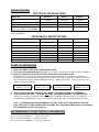
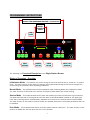
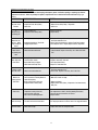
BREW CENTER-IT, COFFEE BREWING EQUIPMENT
MODELS
Single
BC301-IT
Twin
BC2-IT
BC302-IT
MANUAL
Specifications
Installation
Operating Instructions
Programming Instructions
Care Maintenance
Adjustments
Parts Identification
Wiring Diagram
Cecilware sells value... Worldwide
43 -05 20th Avenue, Long Island City, NY 11105
TEL: 718-932-1414
FAX: 718-932-7860
Ni90A 11/15/2000
SPECIFICATIONS
ELECTRICAL SPECIFICATIONS
MODEL NO.
BC301-IT
BC2-IT
BC302-IT
Volts
Watts
120/240
4100
120/240
6200
120/240
6200
18
6-20R
27
6-30R
27
6-30R
Amps
Wall Outlet (Receptacle)
Power Cord CE202 – 30A optional
All Brew Centers are single phase with 3 wires plus a ground with cord and plug, except Eport 220V,
1 PH, (UROPEAN).
MECHANICAL SPECIFICATIONS
MODEL NO.
Tank Capacity (US gal.)
Cups/Brew Cycle
Cups/Hour
Height (includes 4” legs)
Width
Depth (+2”for ¼"water connection)
Ship Weight lbs.
BC301-IT (in)
BC2-IT (in)
BC302-IT (in)
3.1
6.2
6.2
12/24/36
2 x 36
2 x 12/24/36
240
400
400
31
9¼
17 ½
31
18
17 ½
31
18
17 ½
65
105
110
START-UP PROCEDURE
1. PLUG THE POWER CORD INTO A PROPER RECEPTACLE.
2. ACTIVATE THE POWER SWITCH ON (Toggle Up), located in the lower left corner in back of Brewer.
3. PUSH THE POWER BUTTON (RED) ON THE TOUCHPAD ON THE FRONT PANEL.
The power switch controls all power including the Heater Elements in the tank and the Warmers.
The Brewer will automatically start filling the tank, then it will start to heat up the Water in the tank,
until it reaches the proper preset temperature (200°F) (About 20 minutes). The LCD window will
display a series of messages:
CECILWARE shows day
NG39A shows time
FILLING
TANK
HEATING
shows temp
shows day
shows time
shows day
shows time
READY
TO BREW
shows day
shows time
4. PLACE PAPER FILTER AND COFFEE IN THE FUNNEL, AND INSERT FUNNEL IN THE BREWER.
5. PUSH THE BREW BUTTON. YOU NEED NOT WAIT FOR THESE MESSAGES TO COME UP FIRST.
After the brew button is pressed, when the “READY TO BREW” message comes on, the Brewer
automatically begins brewing coffee. The LEDs will light up and stay on during the brewing cycle.
NOTE: THE BREWER CAN BE PROGRAMMED TO START ITSELF UP AT ANY DESIRED TIME AND
SHUT ITSELF OFF AT ANY DESIRED TIME, PROVIDED THAT THE MAIN POWER SWITCH IN THE BACK
OF THE BREWER IS KEEPT ON (Toggle Up).
RECOMMENDED COFFEE AMOUNT FOR BREWING
2.5 oz. for one (1) decanter, ½ US gal. (12 cups)
5 oz. for two (2) decanters, 1 US gal. (24 cups)
7.5 oz. for tree (3) decanters, 1½ US gal. (36 cups)
2
FEATURES AND BENEFITS OF THE DIGITAL, MEMBRANE CONTROL TOUCH PAD BREWER
1. 100% Solid State Control for improved reliability.
2. Modular design and reduced component count for ease of service.
3. Optional Low Water Temperature Lockout to prevent dispensing at water temperatures below an adjustable threshold.
4. Redundant system interlocks for uncompromising user safety.
5. Large two line display for viewing system status on digital display and modifying parameters.
6. Individual brew cycle counters and totalizers for product marketing information and inventory control.
7. Advanced system diagnostics that continuously monitor the status of valves, sensors, and heaters to ensure proper
operation and aid in identifying potential problems.
8. Protection from heater burnout due to low water level in the reservoir tank.
9. Stable water temperature regulation with adjustment to one-degree Fahrenheit.
10. Units of measure displayed in either English or Metric.
11. Digital adjustment of brewing size in ounce.
12. Audible alarms: a) When brew cycle is ready b) Warmers Warning “time to brew new batch of coffee”.
13. Optional power saving “sleep mode” for extended periods of inactivity (self turn off and on, as programmed).
3
INSTALLATION AND OPERATING INSTRUCTIONS
Warranty is void if the Brewer is connected to any Voltage other than the Voltage specified on the data
label of the Brewer.
UNPACKING AND INSPECTION
Carefully unpack the Brewer by cutting the straps and lifting the carton off the Brewer.
ASSEMBLY AND SET-UP
The Brewer is shipped complete with:
DESCRIPTION
Adjustable legs
Carriers complete with Faucets and Covers
Funnels with sample Filter pack
BC1-301-IT
4
1
1
BC2-IT, 302-IT
4
2
2
Remove carriers from Brewer, one has the four (4) legs packed inside. Install legs by tilting Brewer on its
back and screwing the legs into the threaded leg supports on bottom.
WATER HOOK UP
The National Sanitation Foundation (NSF) requires the following for NSF approved installation:
1. A quick disconnect water connection or enough extra coiled tubing (at least 2x the depth of the unit) so
that the Brewer can be moved for cleaning underneath.
2. An approved flow-back prevention device such as a double check valve to be installed between Brewer
and water supply.
WATER CONNECTION
The Brewer comes equipped with a ¼ inch compression water inlet fitting located in the back. Use a ¼ inch
copper tubing to connect the Brewer to a cold water supply. Water pressure should be: 20 PSI min. to 90
PSI max. An external shut-off valve and a water filtering system with a charcoal filter are highly
recommended.
Turn water supply on and check for leaks at the water inlet connections, tighten compression fitting if
necessary.
ELECTRICAL CONNECTIONS
A terminal block inside the base compartment is provided for electrical connections. Opening for field
conduit connections are provided in the bottom and the back of the base.
To access the Terminal Block, loosen the 2 screws on the side of the base cover. Disengage base cover
from rear panel by lifting base cover up and lifting back towards rear panel.
Power Cord CE202 - Optional
RECOMMENDED WIRING SIZES
Model No.
BC301-IT
BC2-IT, BC302-IT
Single (1) Phase
12 AWG
10 AWG
Note:
1. Neutral (N) and Ground Wires to be 14 AWG Minimum.
2. Field wiring must be suitable for 75º C.
3. Use Copper wire only for all power supply connections.
4
PROGRAMMING INSTRUCTIONS
TO ACCESS PROGRAMMING – Press Simultaneously Both Buttons
TO SCROLL THRU PROGRAMMING FUNCTIONS – Press One Button
TO CHANGE
OR RESET
PARAMETER
VALUES
LED
LIGHTS
microprocessor driven
LCD WINDOW
CANCEL
CAUTION
CANCEL
HOT WATER
POWER
BREW
BUTTONS
WARMER
BUTTON
POWER
BUTTON
CANCEL LAST
OPERATION
The following is a Functional Description of the Single Station Brewer:
Modes of Operation - Overview
Initialization Mode – This mode is only active during the first few seconds after a “power-on” or system
reset. The main function of this mode is to perform some special self-testing functions and configure the
system using the previously saved operating parameters.
Normal Mode – This mode becomes active immediately after Initializing Mode has completed its tasks.
The main functions of this mode are to monitor and report system status and control brewing.
Service Mode – This mode becomes active when the hidden keys under the Cecilware Logo (located on
the upper-left-hand side of the keypad) and the first letter of the Model Name (located on the upper-righthand side of the keypad) are simultaneously depressed for more than two seconds while in Normal Mode.
The main function of this mode is to allow access (for qualified personnel) to all system parameters that can
be modified.
Error Mode – This mode becomes active when the system detects a fatal error. The main function of this
mode is to disable the unit and report the error to the operator.
5
MODES OF OPERATION – DESCRIPTIONS
Initialization Mode:
The following screen signifies the presence of this mode:
CECILWARE
&&&&& REV #.#
Description – This mode is active only during the first few seconds after “power-on”. The purpose of
the Initialization Screen is to identify the System Software Title (depicted by “&&&&&”) and Revision
Number (depicted by “#.#”).
SSSSSS
DDD K
Normal Mode:
SSSSSS HH:MMP
The following screen signifies the presence of Normal Mode:
Description – Normal Mode is active immediately after Initialization Mode. The left half of the screen
displays the present System State (depicted by “S”). Refer to the subsequent State Descriptions in this
section for more information on System States. The right half of the screen displays the present day of
the week (depicted by “D”), the present time (depicted by “HH”:”MMP”), and the current KeyLock
Status (depicted by “K”). The day of the week is identified using familiar three letter abbreviations.
The time is identified using hours and minutes along with a “AM/PM” indicator. If KeyLock is enabled
the” KL” symbol will be present. Enabling KeyLock will prevent unauthorized users from operating the
unit. Refer to the Service Mode Descriptions for more information on the KeyLock function.
FILLING DDD K
Filling State
TANK HH:MMP
Description – This screen is displayed during the initial filling of the water tank (first fill). Once the
water in the reservoir tank has reached the appropriate fill level this screen is retired.
HEATING DDD K
Heating State:
TTTF
HH:MMP
Description – This screen is displayed when the present water temperature is below the Lockout
Temperature Set Point. The actual water temperature is displayed in the lower left-hand portion of the
screen (depicted by “TTTF”). If the Brew Key is depressed while in the Heating State the system will
advance to the Waiting State. If the Brew Key is depressed for more that three seconds the Waiting
State is bypassed and the system will advance to the Brewing State.
WAITING DDD K
TTTF
HH:MMP
Waiting State
Description – This screen is displayed when the operator presses the Brew Key while the system is in
the Heating State. The actual water temperature is displayed in the lower left-hand portion of the
screen (depicted by “TTTF”). The Brew Key LED will blink in this state. Once the water temperature
reaches the Lockout Temperature Set Point the system will automatically advance to the Brewing
State.
Pressing the Brew Key or the Cancel Key while in the Waiting State will cause the system to revert
back to the Heating State.
READY
DDD K
Ready (to Brew) State
TO BREW HH:MMP
Description – This screen is displayed when the system is ready to begin a Brew Cycle. Pressing the
Brew Key while in the Ready State will advance the system to the Brewing State (i.e. begin a Brew
Cycle).
6
BREWING DDD K
MM:SS HH:MMP
Brewing State
Description – This screen is displayed when a Brew Cycle is in progress. The time remaining in the
Brew Cycle is displayed in the lower left-hand corner of the screen (depicted as “MM:SS”). The Brew
Key LED will blink in this state. The Main Warmer is automatically activated upon entry into this state.
The Brewing parameters of Brew Size, Dilution, Pre-Infusion, Pulse Brew, and Drip Time are utilized in
this state. Refer to the Service Mode Descriptions for more information on Brew parameters.
Pressing the Brew Key or the Cancel Key while in the Brewing State will abort the Brew Cycle and
revert the system to the Ready State.
-Brew Fill Constant Calibration State
Description – The Brew Fill Constant Calibration State is entered from the Heating State or the Ready
State by simultaneously pressing the [Down Arrow] Key and the Brew Key. The system will
immediately energize the Dump Solenoid (and dispense hot water) for exactly 10 seconds. The
required Brew Fill Constant can be verified by dividing the volume of hot water dispensed by 10 thus
yielding the actual Brew Fill Constant in ounces per second.
--Dilution Fill Constant Calibration State
Description – The Dilution Fill Constant Calibration State is entered from the Heating State or the
Ready State by simultaneously pressing the [Up Arrow] Key and the Brew Key. The system will
immediately energize the Dilution Solenoid (and dispense hot water) for exactly 10 seconds. The
required Dilution Fill Constant can be verified by dividing the volume of hot water dispensed by 10 thus
yielding the actual Dilution Fill Constant in ounces per second.
--Warmers
Description – The warmers are generally controlled manually via the Warmer Keys on the keypad.
The only situation when this is not the case is during a Brewing Cycle. The Main Warmer is
automatically turned ON when the system enters the Brewing State. Each Warmer has an optional
timer, power level, audible alarm, and power reduction feature associated with it. The Warmer Timer is
particularly useful to indicate when a brew has become stale. Refer to the Service Mode Descriptions
for more information on Warmer options.
--Real-Time-Clock
Description – The Real-Time-Clock (RTC) allows the system to automatically turn ON at a specified
time (usually in the morning) and turn OFF at a specified time (usually at night). The RTC also has
separate settings for weekdays and weekends. This feature eliminates the wait associated with
heating up the reservoir tank every morning. Refer to the Service Mode Descriptions for more
information on Real-Time-Clock parameters.
7
SERVICE MODE
Description – The main function of Service Mode is to give qualified personnel the ability to configure the
system to meet the requirements of each installation.
General Conventions (unless otherwise indicated)
1)
2)
3)
4)
5)
6)
To enter or exit Service Mode simultaneously depress both the hidden key under the Cecilware Logo
(CW Key) and the hidden key under the first letter of the Model Name (MN Key) until the buzzer
sounds (approximately two seconds).
Depressing the MN Key will cause the menu to scroll up and depressing the CW Key will cause the
menu to scroll down.
Depressing the [Up Arrow] Key or [Down Arrow] Key individually will increase, decrease, or toggle
the displayed parameter respectively.
Simultaneously depressing both the [Up Arrow] Key and the [Down Arrow] Key is used to
acknowledge a request for confirmation (i.e. ARE YOU SURE?).
Modified parameters are saved upon scrolling to a different menu.
The system will automatically exit Service Mode and enter Normal Mode if the keypad remains idle
(i.e. no keys are pressed) for more then three minutes.
KEYLOCK
KEYLOCK
ON/OFF
Description – The KeyLock feature disables all keys on the keypad except the Power Key. This feature
prevents unauthorized users from tampering with the controls. For user convenience a method has been
provided to temporarily override KeyLock. While depressing the hidden Cecilware (CW) Key the KeyLock
feature is disabled. This allows authorized users to easily start a Brew Cycle while preventing unauthorized
users from doing the same. The presence of the “KL” symbol on the screen in Normal Mode indicates the
status of KeyLock (see Normal Mode Descriptions).
DISPENSE TOTAL
DISPENSE TOTAL
######## OZ
Description – The Dispense Total is the total volume of hot water automatically dispensed since the
machine was assembled at the factory. This value cannot be changed or reset!
BREW CYCLES
BREW CYCLES
#####
Description – The Brew Cycles screen displays the value of the Brew Cycle Counter. The Brew Cycle
Counter contains the total number of completed Brew Cycles since the counter was last reset. The Brew
Cycle Counter can be reset (set to zero) by simultaneously depressing the [Up Arrow] Key and [Down
Arrow] Key for approximately two seconds.
BREW SIZE
BREW SIZE
###.# OZ
Description – The Brew Size is the required volume of hot water dispensed during each Brew Cycle.
BREW FILL CONSTANT
BREW FILL CONST
#.## OZ/SEC
Description – The Brew Fill Constant is the exact value of the rate at which hot water is dispensed from
the Dump Solenoid Valve during each Brew Cycle. The accuracy of this value is crucial to the proper
operation of this system. This value is directly related to the orifice size of the Dump Solenoid Valve. A
simple method for calibrating the Dump Solenoid Valve has been provided in Normal Mode (see Brew Fill
Constant Calibration section of Normal Mode Descriptions).
PRE-INFUSION
PRE-INFUSION
ON/OFF
Description – The Pre-Infusion feature gives the user the ability to “wet” the grinds for a period of time
(Infusion Time) and then allow the grinds to “soak” for a period of time (Soak Time) before brewing.
8
INFUSION TIME
INFUSION TIME
## SECONDS
Description – The Infusion Time is the amount of time that the system will dispense (infuse) hot water into
the grinds during the Pre-Infusion process.
SOAK TIME
SOAK TIME
## SECONDS
Description – The Soak Time is the amount of time that the system will wait between the end of the hot
water infusion period and the beginning of brewing.
PULSE BREW
PULSE BREW
ON/OFF
Description – The Pulse Brew feature gives the user the ability to brew by non-continuously dispensing
(pulsing) hot water.
PULSE ON TIME
PULSE ON TIME
## SECONDS
Description – The Pulse ON Time is the amount of time that the system will continuously dispense hot
water during a Brew Cycle.
PULSE OFF TIME
PULSE OFF TIME
## SECONDS
Description – The Pulse OFF Time is the amount of time that the system will wait between hot water
dispenses during a Brew Cycle.
DRIP TIME
DRIP TIME
### SECONDS
Description – The Drip Time is the amount of time that the system will wait after the completion of the hot
water dispense before signaling the end of the Brew Cycle. This allows time for any water remaining in
the funnel to drain out.
DILUTION
DILUTION (36)
ON/OFF
Description – The Dilution feature gives the user the ability to add hot water directly to the brew without
passing through the grinds. This option is only available in models with a 36-Cup Dispense Key.
DILUTION PERCENT
DILUTION PERCENT
## %
Description – The Dilution Percent is the percentage of the total volume of the brew (Brew Size) that is
diluted
DILUTION FILL CONSTANT
DIL FILL CONST
#.## OZ/SEC
Description – The Dilution Fill Constant is the exact value of the rate at which hot water is dispensed from
the Dilution Solenoid Valve during each Brew Cycle. The accuracy of this value is crucial to the proper
operation of this system. This value is directly related to the orifice size of the Dilution Solenoid Valve. A
simple method for calibrating the Dilution Solenoid Valve has been provided in Normal Mode (see Dilution
Fill Constant Calibration section of Normal Mode Descriptions).
DILUTION DELAY
DILUTION DELAY
### SECONDS
Description – The Dilution Delay is the amount of time the system waits from the start of Brewing to the
start of Dilution.
WATER TEMPERATURE
WATER TEMP
### °F
Description – The Water Temperature is the required (set point) temperature of the water in the reservoir
tank.
9
TEMPERATURE SENSOR CALIBRATION
TEMP SENSOR CAL
ARE YOU SURE ?
Description – The Temperature Sensor Calibration allows the user to offset (calibrate) the displayed water
temperature to a reference thermometer.
TEMP SENSOR CAL
Instructions – Use the [Arrow] Keys to adjust (calibrate) the displayed
temperature to match the reference thermometer. Depress one of the
### °F
[Hidden] Keys when the calibration is complete.
LOCKOUT TEMPERATURE
LOCKOUT TEMP
### °F
Description – The Lockout Temperature is the minimum brewing temperature. The system will not allow a
Brew Cycle to begin unless the water is above the Lockout Temperature.
SLEEP TIMER
SLEEP TIMER
ON/OFF
Description – The Sleep Timer feature automatically reduces the water temperature to three degrees above
the Lockout Temperature if the machine has not started a Brew Cycle within two hours.
WARMER POWER
WARMER POWER
### %
Description – The Warmer Power feature allows the user to reduce the actual heating power of the
warmers. The percentage displayed is percentage of maximum power.
WARMER TIMER
WARMER TIMER
ON/OFF
Description – The Warmer Timer feature allows the user to set the maximum length of time a brew remains
fresh while being warmed. Once the Warmer Timer has expired an alarm is generated. An alarm consists
of a blinking warmer LED and (optionally) the audible alarm (buzzer) sounding. The Warmer Timer is reset
(restarted) by cycling the warmer Off and On.
AUDIBLE ALARM
AUDIBLE ALARM
ON/OFF
Description – The Audible Alarm feature allows the user to enable/disable the buzzer from indicating that
the Warmer Timer has expired.
WARMER TIME
WARMER TIME
### MINUTES
Description – The Warmer Time is the length of time that a warmer can be continuously energized before
an alarm is generated.
WARMER REDUCTION
WARMER REDUCTION
ON/OFF
Description – The Warmer Reduction feature allows the user to gradually reduce the actual heating power
of the warmers. This reduction of power is taken over the Warmer Timer period.
REDUCTION PERCENTAGE
REDUCTION PCT
### %
Description – The Reduction Percentage is the percentage of Warmer Power that is gradually reduced over
the Warmer Time.
WEEKDAY TIMER
WEEKDAY TIMER
ON/OFF
Description – The Weekday Timer function allows the system to automatically turn ON at a specified time
and turn OFF at a specified time every weekday (Monday – Friday).
WEEKDAY TIME ON
WEEKDAY TIME ON
##:## #M
Description – The Weekday Time ON function allows the user to set the required weekday turn ON time.
10
WEEKDAY TIME OFF
WEEKDAY TIME OFF
##:## #M
Description – The Weekday Time OFF function allows the user to set the required weekday turn OFF time.
WEEKEND TIMER
WEEKEND TIMER
ON/OFF
Description – The Weekend Timer function allows the system to automatically turn ON at a specified time
and turn OFF at a specified time every weekend (Saturday - Sunday).
WEEKEND TIME ON
WEEKEND TIME ON
##:## #M
escription – The Weekend Time ON function allows the user to set the required weekend turn ON time.
WEEKEND TIME OFF
WEEKEND TIME OFF
##:## #M
Description – The Weekend Time OFF function allows the user to set the required weekend turn OFF time.
CLOCK SETUP
CLOCK SETUP
ON/OFF
Description – The Clock Setup function allows the user to adjust (set and calibrate) the systems Real-TimeClock.
ADJUST SECONDS
ADJUST SECONDS
DAY HH:MM:##
Description – The Adjust Seconds function allows the user to adjust (set) the systems Real-Time-Clock
Seconds placeholder.
ADJUST MINUTES
ADJUST MINUTES
DAY HH:##:SS
Description – The Adjust Minutes function allows the user to adjust (set) the systems Real-Time-Clock
Minutes placeholder.
ADJUST HOURS
ADJUST HOURS
DAY ##:MM:SS
Description – The Adjust Hours function allows the user to adjust (set) the systems Real-Time-Clock Hours
placeholder.
ADJUST DAY
ADJUST DAY
### HH:MM:SS
Description – The Adjust Day function allows the user to adjust (set) the systems Real-Time-Clock Day
placeholder.
CLOCK CALIBRATION CONSTANT
CLOCK CAL CONST
##
Description – The Clock Calibration Constant function allows the user to calibrate the systems Real-TimeClock (RTC). Each unit corresponds to approximately five seconds per month. Thus, if the RTC is running
five seconds slow per month then the Clock Calibration Constant needs to be increased by one.
Conversely, if the RTC is running five seconds fast per month then the Clock Calibration Constant needs to
be decreased by one.
UNITS
UNITS
ENGLISH/METRIC
Description – The Units function allows the user to select English (oz, °F) or Metric (mL,°C) units of
measure.
DEFAULT VALUES
DEFAULT VALUES
ARE YOU SURE ?
DEFAULT VALUES
Description – The Default Values function allows the user to set all
COMPLETED
system parameters back to their Factory Default Settings. This provides
a known (reference) configuration for troubleshooting purposes.
11
ERROR MODE
Description – The main function of Error Mode is report any system malfunctions and to disable the
unit The system must be “powered down” using the Power Key located on the membrane keypad
to reset any reported error
KEYPAD
! SYSTEM ERROR !
KEYPAD
Description – This screen is displayed and the unit is disabled when a key-press is detected during
the initial application of power to the system. This test is not performed during a Power Key
initiated “power-on” sequence.
Possible Causes – Membrane Keypad or someone depressing a key while applying power to the
system
110/220VAC ON
! SYSTEM ERROR !
110/220VAC ON
Description – This screen is displayed and the unit is disabled when line voltage is detected before
the Safety Relay is energized.
Possible Causes – Wiring or Safety Relay
110/220VAC OFF
! SYSTEM ERROR !
110/220VAC OFF
Description – This screen is displayed and the unit is disabled when line voltage is not detected
after the Safety Relay is energized.
Possible Causes – Wiring, Fuse, High Temp Limit Switch, Control Card, or Safety Relay
HIGH WATER TEMP
! SYSTEM ERROR !
HIGH WATER TEMP
Description – This screen is displayed and the unit is disabled when the present water temperature
is sensed as being higher than 208 °F.
Possible Causes – Wiring, Power Triac, Control Card, or Water Temperature Sensor
OVER FLOW
! SYSTEM ERROR !
OVER FLOW
Description – This screen is displayed and the unit is disabled when the Over Flow Level Sensor is
detecting the presence of water.
Possible Causes – Wiring, Fill Solenoid, Control Card or Level Sensor
NO FILL RESPONSE
! SYSTEM ERROR !
NO FILL RESPONSE
Description – This screen is displayed and the unit is disabled when the Fill Solenoid has been
continuously energized (open & filling) for more than 15 minutes during the first fill or more than 30
seconds thereafter.
Possible Causes – Water Supply is turned off, Wiring, Control Card, Fill Solenoid, or Level Sensor
NO TEMP RESPONSE
! SYSTEM ERROR !
NO TEMP RESPONSE
Description – This screen is displayed and the unit is disabled when the Water Heater has been
continuously energized (heating) for more than 45 minutes.
Possible Causes – Wiring, Control Card, Water Temperature Sensor, Power Triac, or Water Heater
DUMP #1 CLOSED
! SYSTEM ERROR !
DUMP #1 CLOSED
Description – This screen is displayed and the unit is disabled when the system has been brewing
(dispensing) for more than one minute and the Level Sensor has not sensed the absence of water.
Possible Causes – Wiring, Control Card, or Dump Solenoid.
TEMP SENSOR
! SYSTEM ERROR !
TEMP SENSOR
Description – This screen is displayed and the system is shut down when the Water Temperature
Sensor is detecting an invalid (below 32°F or above 220°F) water temperature.
Possible Causes – Wiring, Control Card, or Temperature Sensor.
12
BC302-IT FRONT VIEW
BC2-IT OPEN FRONT
1
2
3
4
5
6
7
8
9
10
11
12
PARTS IDENTIFICATION
BC301-IT
ITEM P/N QTY P/N QTY
DESCRIPTION
1 SF26A 1 SB49A 1 CABINET TOP COVER
-- TOUCH PAD LABEL:
--2
----NG35A 1 NG40A 1 BC1-IT /BC2-IT
NG37A 1 NG36A 1 BC301-IT / BC302-IT
NG39A 1 BC120-IT
3 DO42A 1 D042A 2 FAUCET, HOT WATER
4 SF28A 1 SB66A 1 FRONT COVER
5 SF27A 1 SB65Q 1 CABINET FRAME ASS'Y
6 V210Q 1 V210Q 2 FUNNEL ASS'Y, BLACK
7 SF74Q 1 SC81Q 1 TANK WELDMENT ASS’Y
8 R615A 1 SC86A 1 BASE WARMER COVER
9 G108A 1 G108A 2 WARMER ELEMENT
10 M090A 2 M090A 4 GROMMET F/HEAT SHIELD
11 U485A 1 U485A 2 HEAT SHIELD
12 M172S 1 M172S 1 LEGS [SET OF 4]
13
14
15
16
L069A
K331A
C396Q
CE202
BC2-IT, BC302-IT BACK VIEW
BC2-IT
BC302-IT
1
1
1
1
L069A
K331A
C396Q
CE202
1
1
1
1
POWER SWITCH
ELBOW FITTING, IN. VALVE
FUSE HOLDER ASS’Y
POWER
CORD
30AOPTIONAL
13
14
15
16
13
TOP CABIN OPEN VIEW BC302-IT
20
1
19
2
18
3
17
4
16
5
15
6
14
7
13
12
11
8
9
10
TOP CABIN - PARTS IDENTIFICATION
ITEM
P/N
BC301-IT
QTY
1
2
3
4
5
6
7
8
9
10
11
L656A
L671A
K355Q
L688A
L689A
CH87A
L553A
B203A
L669A
M483A
K671Q
M197A
SD06Q
E107A
K668A
M483A
M483A
K683A
M483A
K525A
P465A
G367A
G369A
G286A
RK70A
1
1
1
1
1
1
1
1
1
1
1
1
1
1
1
1
1
1
1
1
1
1
12
13
14
15
16
17
18
19
20
1
P/N BC2-IT QTY
BC302-IT
L656A
L671A
K355Q
L688A
L689A
CH87A
L553A
B203A
L669A
M483A
K671Q
M197A
SD06Q
E107A
K668A
M483A
M483A
K683A
M483A
K525A
P465A
G367A
G369A
G286A
SC82A
2
1
1
2
1
1
1
1
1
2
2
2
2
2
2
1
2
1
1
1
1
2
1
DESCRIPTION
HI-LIMIT
THERMISTER PROBE
WATER LEVEL CONTROL PROBE
DINSPENSE VALVE, SINGLE
DINSPENSE VALVE, DUAL, BYPASS
TRANSFORMER
RELAY, 120V, 25A (HEATER SAFETY) [USED IN 240V UNITS ONLY]
RELAY, 110V, 15A (POWER SAFETY)
CONTROL BOARD
SILICONE HOSE ( .312”ID x 7”L)
SPRAY HEAD FITTING ASS’Y WITH
RUBER WASHER
SPRAY HEAD BASE ASS’Y
SPRAY HEAD
NUT
SILICONE HOSE ( .312”ID x 11”L)
SILICONE HOSE ( .312”ID x 6”L)
SAFETY OVERFLOW FTB
SILICONE HOSE ( .312”ID x 10.5”L)
S.S ELBOW TUBE
SCREW, ¼-20 x 5/8
HEATER (1.7 KW 120V) OR
HEATER (3.0 KW 230V) OR
HEATER (4.0 KW 230V)
TANK TOP
14
TOP CABIN OPEN VIEW BC301-IT
BOTTOM CABIN OPEN VIEW
6
5
1
4
2
3
BOTTOM CABIN - PARTS IDENTIFICATION
ITEM
P/N
BC301-IT
QTY
1
2
3
4
5
6
L069A
CD257
B083A
CE202
C396Q
L615A
1
1
1
1
1
1
P/N
BC2-IT QTY
BC302-IT
L069A
CD257
B083A
CE202
C396Q
L615A
1
1
1
1
1
1
15
DESCRIPTION
POWER SWITCH
WATER INLET VALVE
TERMINAL BLOCK
POWER CORD
FUSE HOLDER ASS’Y
TRIAC, 15 Amps
FRONT VIEW – BC301-IT
BACK VIEW – BC301-IT
CLEANING AND SANITIZING
SANITIZING:
All food dispensing units should be sanitized periodically. All parts to be sanitized must be cleaned first.
To prepare a sanitizing solution:
ADD 2 TSP. OF LIQUID CLOROX BLEACH (5.25% CONCENTRATION) TO 1 GALLON OF WATER AT ROOM TEMPERATURE (70°- 90°F).
Note: Always start with a unopened bottle of Clorox Bleach since the solution from an opened bottle has a short life span.
• Soak all parts for a minimum of 3 min. in the sanitizing solution.
• Let all sanitized parts drain and dry naturally. DO NOT WIPE THEM DRY.
• Before using the sanitized unit (or parts) with food stuffs, rinse all parts thoroughly with water.
Water pipe connecting and fixtures directly connected to a potable water supply shall be sized, installed, and maintained in accordance with
Federal, Sate, and Local codes (section 7).
CLEANING:
1. Empty contents from brew funnel, wash and let dry (use a mild dishwasher detergent).
2. To wipe all surfaces of the machine, turn the power switch to OFF first, then wipe surfaces, then turn power back ON.
16
TROUBLESHOOTING GUIDE
WARNING: To reduce the risk of electrical shock unplug the dispenser power cord before repairing or replacing any internal
components of the unit.. Before any attempt to replace a component be sure to check all electrical connections for proper
contact
PROBLEM
PROBABLE CAUSE
REMEDY
1.
No power to the
machine.
a) Loose wire connection.
b) Inoperative Power Safety Relay
c) Blown fuse.
a) Check wire connections to Relay. See Power Safety Relay Test.
b) Replace Power Safety Relay, if inoperative.
c) Check fuse.
2.
Machine keeps
repeating cycle.
a) Touch Pad defective.
b) Inoperative Power Safety Relay.
a) Replace Touch Pad.
b) Replace Relay.
3.
Water does not
shut off. Water
keeps running into
funnel.
3.
Water will not
stop flowing into
tank.
a) Leaking Water Inlet Valve [Solenoid].
a) Clean/check fittings of Valve. Replace Valve if needed.
See ”Water Inlet Valve Test”
b) Check Touch Pad connections. Replace Touch Pad if needed.
c) Clean Dispense Valve. Replace Dispense Valve if inoperative.
a) Water Level Probe malfunction.
b) Water Inlet Valve malfunction..
a) Check Probe. Replace if necessary. See “Probe Test”
b) Check Solenoid. Replace if necessary. See “Water Inlet Valve
Test”
4.
Water drips from
brew funnel.
a) Leaking Dispense Valve.
b) Too much water in tank.
c) Spray Head Fitting is clogged.
d) Water Valve blocked by scales.
a) Replace Water Dispense Valve.
b) Dispense some water from tank.
c) Clean Spray Head Fitting.
d) Replace or clean Valve Seat.
5.
No water is going
into tank at all.
a) Water Inlet Valve (Solenoid) malfunction.
a) Check Water Inlet Valve. Replace if necessary.
See “Water Inlet Valve Test”
b) Check Probe. Replace if necessary. See “Probe Test”.
6.
Water is not
heating up in the
water tank.
a) Temperature setting is incorrect.
b) Loose connection to Heating Element or
Heater Safety Relay.
c) Heater is burned out or defective.
d) Inoperative Heater Safety Relay.
a) Set Temperature at 200°F – See Programming Instructions.
b) Make sure all wires are tight.
a) Run out of hot water in tank.
b) Temperature setting is incorrect.
c) Loose electrical connection.
d) Bad or burnt out Heating Element.
a) Allow time for water in tank to heat after filling.
b) Set temperature at 200°F. (See Programming Instructions)
c) Check all electrical connections for contact.
d) Replace Heater.
8.
Coffee too strong.
a) Water flow too low.
b) Too much coffee in the brew funnel.
a) Adjust water flow rate on Dispense Valve.
b) Put the proper amount of coffee in funnel. See suggested amount.
9.
Coffee too weak.
a) Not enough coffee in the brew funnel.
b) Water flow too high.
a) Add coffee.
b) Adjust water flow rate on Dispense Valve.
7.
Cold coffee.
b) Inoperative Switches on Touch Pad.
c) Clogged Dispense Valve
b) Water Level Probe malfunction.
c) Replace the Heater.
d) Replace Heater Safety Relay, if inoperative. See Heater Safety
Relay Test.
17
SPECIAL COMPONENTS TEST AND ADJUSTMENTS
1) WATER INLET VALVE (SOLENOID) TEST (Located inside bottom cabin)
Turn power off from touchpad. If the water level rises inside the tank, and shoots out of
the overflow, the Water Inlet Valve is leaking. Disconnect wires from the Water Inlet Valve
coil and connect a 2 wire line cord to the terminals. Plug it into a 115V outlet. If water
flows in and stops when you pull it out, the Valve is working fine. Repeat this test a few
times. The problem may be in the Probe. If the water does not flow in when the cord is
plugged into an electrical outlet, the Solenoid coil may be damaged, opened or the valve
may have an obstruction preventing the water from flowing in. Clean or replace it.
A Check Valve is installed to prevent backflow.
To check proper function of Check Valve, disconnect water line from the Check Valve,
check for dripping from the disconnected end of the Check Valve.
If it leaks replace it.
Water inlet Valve max. flow rate is 1.3 gal/min.
2) WATER LEVEL PROBE TEST (Located on tank top, inside top cabin)
If there is a lack of water, you will get an error message on the LCD window.
Check the probe as follows:
Turn on the power from touchpad and water supply. Check inside the tank to make
sure the water is not touching the Probe. Pull the wire and terminal out of the Probe
rod. If water starts flowing into the tank, the Probe may be grounded, due to excessive
liming. Check with Ohm meter. Clean or replace.
3) POWER SAFETY RELAY TEST (Located inside top cabin)
Turn power switch on from touchpad. Measure Voltage across Input to Coil,
between terminals1& 2. Should read approx. 9V to 10V D.C.
Measure Voltage across Output, between terminals “COM” to Ground. Should read 120V.
Measure Voltage across Input, between terminals “NO” to Ground. Should read 120V.
4) HEATER SAFETY RELAY TEST (Located inside top cabin)
Make sure power switch in back of unit is on (toggle up).
Turn power switch on (energize) from touchpad. Measure Input Voltage across coil,
between terminals 0 & 1. Should read 120V.
Measure Output Voltage across Heater Element. Should read 220 V. If there is no Voltage
across the Heating Element, measure Output Voltage between terminals 4 & 8.
Turn power switch off from touchpad. The Voltage should be a constant 220V even when not energized.
Turn power switch on) from touchpad. Measure Voltage across terminals 2 & 6. Should read 220V.
If 120V was applied to relay coil and it does not energize, replace relay.
18
5) CHECK DISPENSE VALVES FOR LIME BUILD-UP (Located inside top cabin)
Drain The Water Tank To Just Below The Level Of The Dispense Valves.
Remove The Valves And Clean. You Can Take These Valves Apart By Hand As Shown.
Replace The Assembly As Needed.
Replace The Valve Into The Tank And Refill tank.
a)
b)
The SINGLE DISPENSE VALVE is factory adjusted to dispense
0.5 oz./sec. of water during the brew cycle (spray duration).
The DOUBLE/ DILUTION DISPENSE VALVE is factory adjusted,
on both sides, to dispense 0.22 oz./sec of water during dilution cycle.
TO ADJUST WATER FLOW RATE:
Locate adjustment screw on valve (as show here).
Using an Allen Key or a flat screwdriver, rotate ¼ turn at a time,
Clockwise (CW) to decrease water flow rate or
Counter-Clockwise (CCW) to increase water flow rate.
Check water flow output after each ¼ turn.
19
TO J3 PIN #3
16 GA TO HEATER
20 GA
MT1
G
MT2
WARMER
DILUTION DUMP
SOLENOID VALVE
120VAC
FILL
SOLENOID
120VAC
#1
HTR
20 GA TO FUSE
16 GA TO SAFETY RELAY
TRIAC L623A 40A
#4
100W
#3
#2
2 4 6 8 10 12 14 16 18 20 22
1 3 5 7 9 11 13 15 17 19 21
J2
THERMISTOR L671A
CONTROL
BOARD
L669A
SAFETY RELAY L553A
OVER-FLOW
HOSE
3
1-
SAFETY RELAY
B190A
K1
K2
4
LEVEL
PROBE
2+
2 4 6 8 10 12 14 16 18
1 3 5 7 9 11 13 15 17
J1
HI-LIMIT
HEATER
TANK
3KW
G
THERMISTOR
L617A SEE
DETAIL-1
FUSE 6 AMP
MT1
MT2
L1
120V/240V INPUT
S1 POWER
SWITCH 120VAC
C1
0.1uf
275V
8VAC
SP1
T1 CH82A
N
L2
TO KEYPAD
J5 (LCD)
TEE #10054
#M683A
J4 (KEYS
B301-IT
KEYPAD NG37A
Brew Ctr
CW
CANC
36
24
OVER TEMPERATURE
SENSOR ASSEMBLY
SEE DATAIL-1
CANC
12
WARM
PWR
WARM
12
24
36
J1
LCD CONTROL
BOARD L669A
J2
J6
P2 LEDS
BATTERY-PANASONIC
#CR2030 OR EQUIVALENT
P5 KEYS
BERG CONNECT0RS
APP'D BY
REV
BY
DATE
DRAWN BY
DESCRIPTION
CECILWARE CORPORATION
TITLE:
ELECTRICAL DIAGRAM
BC301-IT 120/240V
DATE
PART NO NE139
SCALE
REV.
20
DUMP
LEFT
LEFT
RIGHT
DILUTION VALVE
WARMER WARMER SOLENOID RIGHT
RIGHT
DILUTION
SOLENOID
HTR
#7
DUMP
VALVE
LEFT
120VAC
FILL
SOLENOID
#1 120VAC
HTR
#6
100W
#5
100W
#4
#2
#3
2 4 6 8 10 12 14 16 18 20 22
1 3 5 7 9 11 13 15 17 19 21
THERMISTOR L671A
CONTROL
BOARD
L669A
SAFETY RELAY L553A
OVER-FLOW
HOSE
3
K2
6KW
1-
SAFETY RELAY
B190A
K1
4
LEVEL
PROBE
HEATER
TANK
J2
2 4 6 8 10 12 14 16 18
1 3 5 7 9 11 13 15 17
J1
2+
THERMISTOR
L617A SEE DETAIL-1
G
FUSE 6 AMP
MT2
MT1
L1
120V/240V-INPUT
N
L2
S1 POWER
SWITCH 120VAC
C1
0.1uf
275V
8VAC
SP1
T1 CH82A
TEE #10054
#M683A
BC2-IT
KEYPAD NG39A
Brew Ctr
CW
36
CANC
WARM
PWR
WARM
CANC
36
TO KEYPAD
J5 (LCD)
BERG
CONNECT0RS
P2 LEDS
Brew Ctr
CW
J1
CANC
CANC
24
12
J4 (KEYS
TO J3 PIN #3
P5 KEYS
B302-IT
KEYPAD NG40A
36
THERMISTOR
#L617A
OVER TEMPERATURE
SENSOR ASSEMBLY
SEE DATAIL-1
WARM
PWR
WARM
12
24
36
LCD CONTROL
BOARD L669A
J2
J6
TRIAC L623A 40A
BATTERY-PANASONIC
#CR2030 OR EQUIVALENT
BERG
CONNECT0RS
REV
BY
P2 LEDS
P5 KEYS
APP'D BY
DATE
DRAWN BY
DESCRIPTION
DATE
PART NO NE139
SCALE
CECILWARE CORPORATION
TITLE:
ELECTRICAL DIAGRAM
TO SAFETY
RELAY
BC2-IT, BC302-IT
120/240V
21
REV.