1
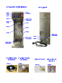
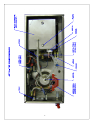
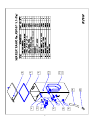
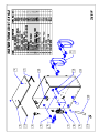
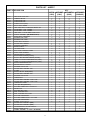
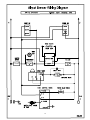
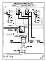
Airpot Coffee Brewers
SPECIFICATIONS AND OPERATION MANUAL
Electrical Specifications:
Model No.
Volts
Phase
Hz.
Watts
Amps
Receptacle
Nema No.
APT18
120
1
50/60
1.8 Kw
APT18WT
120
1
50/60
1.8 Kw
APT100WT
120/240
1
50/60
5.0 Kw
Line cord included. “WT” with Water Tap, “X” for export.
15
15
23
5-15R
5-15R
L14-30R
Circuit
Breaker
15
15
30
NOTES: APT100 Model includes twist lock plug wired for 4 wire 120/240V including Neutral and
Ground.
(120V Models – available on special order and requires a 15amp circuit breaker.)
Water Connections:
¼” flared water inlet fitting and flare nuts for ¼” O.D. copper tubing with a
minimum water pressure of 20 psi.
Dimensional Specifications:
MODEL
Width (Inches)
Depth (Inches)
Height (Inches)
APT18
8
17 1/4
25 1/2
APT100
16
17 1/4
25 1/2
INSTALLATION AND START-UP INSTRUCTIONS
FOR AIRPOT BREWER
Not Included with this Brewer unless ordered separately
2.2 liter Airpot, Part No. V223A
Things to note when Brewing Coffee
•
•
This brewer is set for 2.2 liter capacity Airpot.
Volume can easily be adjusted for 1.9 liter or 2.5 liter Airpots.
WATER HOOK-UP (Check Local Plumbing Codes)
The National Sanitation Foundation (NSF®) requires the following for an NSF approved hook-up:
1. A quick disconnect water connection or enough extra coiled tubing (at least 2x the depth of the unit)
so that it can be moved to clean underneath.
2. An approved back flow prevention device, such as a double check valve, must installed between
brewer and water supply.
Water Connection:
APT Brewers are supplied with 1/4” flared water inlet fittings and flare nuts.
Use a 1/4” diameter copper tubing to connect brewer to a cold water supply line with a minimum water
pressure of 20 psi.
HIGHLY RECOMMENDED: An external water supply shut-off valve near the brewer and a water purifier filter for
better tasting fresh brewed coffee.
2
Electrical Connection:
APT18 - 120 volt, 1.8 kw - Brewers require a single use (dedicated) 15 amp grounded receptacle.
APT100 – 120/240 volt, 6.4 kw - Brewers require a single use (dedicated) 30 amp twist lock
grounded receptacle.
TANK PRIMING PROCEDURES
THESE INSTRUCTIONS ARE FOR INITIAL PRIMING ONLY AND DO NOT HAVE TO BE
REPEATED FOR NORMAL OPERATION.
NOTE: The Heater toggle switch, located in back of unit, or under the top cover, must be in the
OFF POSITION.
1. Remove sample filter pack from brew funnel and insert brew funnel back into machine.
2. Place an empty Air Pot directly under brew funnel.
3. Plug the power cord into a proper receptacle.
4. Activate the RED Power Switch. The tank will start filling automatically. Allow approximately 4-5 minutes
for the tank to fill.
5. After the water tank is filled, activate the Heater Switch ON POSITION. Allow approximately 15-20
minutes for the water to reach a brew temperature (197°F). The heat up time will depend on the water inlet
temperature, the input voltage and the wattage of the elements in the machine.
When the (Green) Ready Light comes on the machine is ready to start brewing.
6. Press Brew Button:
BREWING INSTRUCTIONS FOR COFFEE
1. Place a paper filter into brew funnel and add 2.5 oz. of fresh ground coffee into the filter. Place the funnel back
into brew head of machine.
2. Unlock the Air Pot Cover and remove the Pump Assembly from the Air Pot.
3. Place the Air Pot with cover open on the support shelf under the funnel.
4. When the Green READY light inside the Brew Switch comes on, depress the Brew Switch.
Note: Allow 5 to 6 minutes for the complete brew cycle. DO NOT remove funnel from the brewer until it
has completely stopped dripping
6. Remove AIR POT from the brewer, insert the air pump tube, and snap the top closed.
7. Serve fresh brewed coffee from dispenser nozzle by pushing down the round large button on top of the cover.
ADJUSTMENTS:
Timer Adjustments (To adjust total volume of COFFEE)
1. Turn the Power Switch to OFF and remove the top cover.
2. Locate BREW TIMER and adjust as follows:
3. For MORE volume, turn TIMER KNOB CLOCKWISE.
4. For LESS volume, turn TIMER KNOB COUNTERCLOCKWISE.
5. Go through a complete brew cycle and repeat adjustments if necessary.
CAUTION: Turn TIMER KNOB only in SMALL increments at a time.
Thermostat Adjustments
Thermostat is factory set for proper operating temperature of 197°F to 203°F with the adjustment Knob set to the
maximum clockwise position. If field adjustments are needed proceed as follows:
To DECREASE temperature, turn the control shaft slightly to the left COUNTERCLOCKWISE.
To INCREASE temperature, proceed as follows: With the control knob ALREADY TURNED TO ITS MAXIMUM
CLOCKWISE POSITION, locate the small, slotted ADJUSTMENT SCREW inside the hollow shaft. By using a
narrow blade screwdriver engage the slotted adjustment screw and turn it an 1/8 of a turn slowly to the left
(counterclockwise) until a click is heard and the Green Ready Light goes OFF.
NOTE: Measure the water temperature at the head with the spray head removed in order to capture a solid
stream of hot water. Be sure to REPLACE spray head afterwards.
In HIGH ALTITUDE locations, (5000 ft. above sea level) the thermostat setting will have to be lowered to
prevent boiling.
3
MAINTENANCE TIPS.
1. Remove and clean spray head at least once a week. In hard water areas, inspect and clean every other day.
2. If excessive build up of lime is present, de-lime or replace the heating tank.
CLEANING INSTRUCTIONS
Use a mild dishwashing detergent to clean the STAINLESS STEEL, PLASTIC BREW FUNNELS and AIRPOTS.
Rinse thoroughly. Clean and Polish the outer surfaces of the STAINLESS STEEL AIRPOTS and BREWER with a
STAINLESS STEEL CLEANER & POLISH such as the 3M™ Stainless Steel Cleaner & Polish, which is U.S.D.A.
approved.
TROUBLESHOOTING GUIDE.
Brewing Problems.
Weak Coffee
1. Low water Temperature -------------- Adjust thermostat, should be between 197°F - 203°F
2. Spray Head clogged ------------------- Remove and clean weekly or as needed
3. Too Coarse Coffee Grind ------------ Should be Drip Grind type
4. Not enough Coffee -------------------- Use a minimum of 2 oz. Of coffee
No water from Spray head when brew switch is depressed.
Note: Allow 30 seconds for time delay.
1. Power Switch is off or unit is unplugged.
2. Water Supply is off
3. Hot Water Tank is not full
4. Defective water inlet valve or dispense valve
5. Defective brew switch
6. Defective timer
7. Inlet filter Clogged
Water from spray head not hot.
1. Heater switch is off
2. Thermostat is off or defective.
3. High limit switch has tripped and does not reset – replace high limit switch
3. Tank heater is defective
4
5
6
7
8
9
10
PARTS LIST - AIRPOT
APT18
(120V)
APT18WT
(120V)
QTY
APT18WT-X
(220V)
1
0
1
0
1
1
0
1
0
1
1
0
0
1
0
3
1
1
0
0
1
0
1
0
1
0
1
0
1
1
0
1
0
0
1
0
0
0
1
0
1
1
1
1
2
0
0
1
1
0
0
1
1
0
1
1
1
1
2
0
0
1
1
0
0
1
1
1
1
2
1
1
0
0
0
1
1
1
0
0
0
1
1
1
1
1
1
0
0
1
1
0
0
1
0
0
1
0
1
1
1
2
0
0
1
0
0
1
0
1
0
1
0
0
1
1
1
1
1
0
2
0
2
0
1
4
1
1
2
1
1
0
2
0
2
0
2
0
1
0
0
0
1
1
1
1
2
1
1
2
1
1
1
6
0
1
0
1
1
6
0
1
0
1
1
2
1
2
1
2
1
6
0
1
0
1
1
2
1
2
1
6
1
1
1
1
0
2
1
1
1
1
1
1
0
2
PART # DESCRIPTION
32004
B000A
B177A
B178A
C032A
C072A
C770Q
CD318
CD319
CE202
D085A
E004A
G298A
G382A
K107A
K402Q
K491B
K525A
K544A
K695Q
K671Q
L069A
L155A
L217A
L265A
L265E
L291A
L299A
L467A
L566A
L573A
L579A
L599A
L676A
L681A
L775A
L776A
M008A
M042A
M326A
M391A
M461A
M462A
M494A
M500A
M545A
M600A
P465A
RV33C
SI33C
U810A
V000A
V255Q
INDICATOR LIGHT, RED
TERMINAL BLOCK
CONTACTOR 120V
CONTACTOR 240V
CORD W/ PLUG (120V)
PILOT LIGHT, GREEN
LINE CORD ASSY, 15 AMP 240V, NEMA 6-15P
VALVE INLET - 110V - .66GPM
VALVE INLET - 240V - .66GPM
LINE CORD, 4' L14-30P NEMA TWIST LOCK
FAUCET ASSEMBLY (WT MODELS ONLY)
SPRAY HEAD - BREWERS
ELEMENT 220V 2.4KW
ELEMENT 120V 1.8KW
SPRAY HEAD ADAPTER
WATER LEVEL SENSOR
HOSE NUT ASSEMBLY
ELBOW 90 DEG
1/2" DRAIN TUBE
DUAL LEVEL CONTROL PROBE
SPRAY TUBE ASSEMBLY
HEATER SWITCH, TOGGLE
SWITCH RED ROCKER (POWER)
SWITCH, RED ROCKER NARROW (POWER)
TIMER, HOT WATER DISPENSER 120V (4 MIN)
TIMER, HOT WATER DISPENSER 240V (4 MIN)
SWITCH GREEN BREW 120V
HEATER SWITCH, TOGGLE
DISPENSE VALVE 120V
WATER LEVEL CONTROL 120V
HI LIMIT
SWITCH, BLACK - MOM (BREW)
WATER LEVEL CONTROL 240V
DISPENSE VALVE 220V
THERMOSTAT
WATER LEVEL CONTROL - DUAL 120V
WATER LEVEL CONTROL - DUAL 240V
THERMOSTAT KNOB
LEGS (3/4" ADJ) (SET OF 4)
SILICONE TUBING 3/8 ID x 5/8 OD 2 FT
DRAIN PLUG
SILICONE SEAL 12mm
SEAL, SILICONE 15mm
SEAL, SILICONE 12mm PLUG
SILICONE TANK GASKET
SILICONE TUBING 3/16 ID x 1 FT LONG
SILICONE TANK GASKET
SCREW, 1/4-20 x 5/8 S.S.
WATER TANK ASSEMBLY (REF)
WATER TANK ASSEMBLY (REF)
GUARD BRACKET, HEATER SWITCH
BREW FUNNEL BLACK
FUNNEL ASSEMBLY, ST.STEEL. (OPTIONAL)
11
APT100WT
(120/240V)
12
13