1
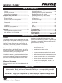
MANUFACTURING
NUMBERS:
9100420
9100424
9100426
9100425
9100428
9100430
9100432
9100433
9100436
9100438
9100439
9100450
9100452
9100456
9100458
9100460
9100462
9100466
9100468
9100480
9100486
C
L IS
T ED
US
AN
I T A T IO
L IS
N
S
MIRACLE STEAMER
T ED
CM
Models MS-150/155,
MS-250/255 & MS-355
P/N 1010699 Rev. M 12/06
MS-255 Shown
Owner ’s Manual
MIRACLE STEAMER
TABLE OF CONTENTS
Owner information .....................................................2
General ......................................................................2
Warranty Information .................................................2
Service/Technical Assistance ....................................3
Important safety information.....................................3
Specifications .............................................................5
Electrical Ratings .......................................................5
Electrical Cord & Plug Configurations .......................5
Model Designation .....................................................5
Dimensions ................................................................6
Installation...................................................................7
Unpacking ..................................................................7
Model MS-150/155 & MS-355 ...................................8
Models MS-250/255 ..................................................9
Operation...................................................................10
General (All Units Except MS-150/250
Mfg. #9100424, 432, 433 & 439) .......................... 10
General (MS-150/250 - Mfg. #9100424, 9100432,
433, & 9100439 Only) ........................................... 10
Operating Instructions (Except MS-150/250
Mfg. #9100424, 432, 433, & 439) ...........................11
Operating Instructions (for MS-150/250
Mfg. #9100424, 432, 433, & 439 ONLY) .................11
Programming ...........................................................11
Hi-Limit Reset Button ............................................. 13
Status Indicator LEDs ............................................. 13
Fault Codes ............................................................ 13
Maintenance ..............................................................14
Daily ........................................................................ 14
Monthly ................................................................... 14
Technical Theory of Operation ............................... 18
Troubleshooting .......................................................19
Replacement parts ...................................................22
Wiring diagrams .......................................................31
Limited Warranty ......................................Back Cover
OWNER INFORMATION
If the unit arrives damaged, contact the carrier immediately and file a damage claim with them. Save all
packing materials when filing a claim. Freight damage
claims are the responsibility of the purchaser and are
not covered under warranty.
General
The Miracle Steamer produces steam using plain tap
water for quick heating and reconstituting of food items.
Simple push button action delivers a fully adjustable
impulse of steam. Because the amount of steam is
consistent, it removes the guesswork and produces a
uniform finished product from one operator to the next.
The warranty does not extend to:
• Damages caused in shipment or damage as
result of improper use.
This manual provides the safety, installation and operating procedures for the Miracle Steamer. We recommend that all information contained in this manual be
read prior to installing and operating the unit.
• Installation of electrical service.
• Normal maintenance as outlined in this manual.
Your Miracle Steamer is manufactured from the finest
materials available and is assembled to Roundup’s
strict quality standards. This unit has been tested at
the factory to ensure dependable trouble-free operation.
• Malfunction resulting from improper maintenance.
• Damage caused by abuse or careless handling.
• Moisture damage to electrical components.
• Damage from tampering with, removal of, or
changing any preset control or safety device.
Warranty Information
Please read the full text of the Limited Warranty in this
manual.
IMPORTANT
A.J. Antunes & Co. reserves the right to change specifications and product design
without notice. Such revisions do not entitle the buyer to corresponding changes,
improvements, additions or replacements for previously purchased equipment.
IMPORTANT! Keep these instructions for future reference. If the unit changes ownership, be sure this manual accompanies the equipment.
2
P/N 1010699 Rev. M 12/06
MIRACLE STEAMER
Service/Technical Assistance
Refer to the service agency directory and fill in the
information below:
If you experience any problems with the installation
or operation of your unit, contact your local Roundup
Authorized Service Agency. They can be found in the
service agency directory packaged with the equipment.
Authorized Service Agency
Name:
Phone No.:
Fill in the information below and have it handy when
calling your authorized service agency for assistance.
The serial number is on the specification plate located
on the rear of the unit.
Address:
Use only genuine Roundup replacement parts in this
unit. Use of replacement parts other than those supplied by the manufacturer will void the warranty. Your
Authorized Service Agency has been factory trained
and has a complete supply of parts for this unit.
Purchased From:
Date of Purchase:
Model No.:
You may also contact the factory at 1-877-392-7854 or
1-630-784-1000 if you have trouble locating your local
authorized service agency.
Serial No.:
Mfg. No.:
IMPORTANT SAFETY INFORMATION
Throughout this manual, you will find the following safety words and symbols that signify important safety
issues with regards to operating or maintaining the Miracle Steamer.
WARNING
WARNING
GENERAL WARNING. Indicates information important to the proper operation of
the equipment. Failure to observe may
result in damage to the equipment and/or
severe bodily injury or death.
ELECTRICAL WARNING. Indicates information relating to possible shock hazard.
Failure to observe may result in damage
to the equipment and/or severe bodily
injury or death.
CAUTION
WARNING
GENERAL CAUTION. Indicates information important to the proper operation of
the equipment. Failure to observe may
result in damage to the equipment.
P/N 1010699 Rev. M 12/06
HOT SURFACE WARNING. Indicates
information important to the handling of
equipment and parts. Failure to observe
caution could result in personal injury.
3
MIRACLE STEAMER
IMPORTANT SAFETY INFORMATION (continued)
-
In addition to the warnings and cautions in this manual,
use the following guidelines for safe operation of the
unit.
•
• Read all instructions before using equipment.
• For your safety, the equipment is furnished with
a properly grounded cord connector. Do not
attempt to defeat the grounded connector.
• Install or locate the equipment only for its intended use as described in this manual. Do not use
corrosive chemicals in this equipment.
• Do not operate this equipment if it has a damaged cord or plug, if it is not working properly, or
if it has been damaged or dropped.
• This equipment should be serviced by qualified
personnel only. Contact the nearest Roundup
authorized service facility for adjustment or repair.
• Do not block or cover any openings on the unit.
• Do not immerse cord or plug in water.
• Keep cord away from heated surfaces.
• Do not allow cord to hang over edge of table or
counter.
The following warnings and cautions appear
throughout this manual and should be carefully
observed.
•
•
•
•
•
• Turn the unit off, disconnect the power source
and allow unit to cool down before performing
any service or maintenance on the unit.
• The equipment should be grounded according to local electrical codes to prevent the
possibility of electrical shock. It requires a
grounded receptacle with separate electrical
lines, protected by fuses or circuit breaker of
the proper rating.
• All electrical connections must be in accordance with local electrical codes and any
other applicable codes.
• WARNING ELECTRICAL SHOCK HAZARD.
FAILURE TO FOLLOW THESE INSTRUCTIONS
COULD RESULT IN SERIOUS INJURY OR
DEATH.
- Electrical ground is required on this appliance.
- Do not modify the power supply cord plug.
If it does not fit the outlet, have a proper
outlet installed by a qualified electrician.
- Do not use an extension cord with this
appliance.
•
4
Check with a qualified electrician if you
are in doubt as to whether the appliance is
properly grounded.
This equipment is to be installed to comply with the basic plumbing code of the
Building Officials and Code Administrators,
Inc. (BOCA) and the Food Service Sanitation
Manual of the Food and Drug Administration
(FDA).
If the supply cord is damaged, it must be
replaced by the manufacturer or its service
agent, or a similarly qualified person.
Do not clean this appliance with a water jet.
Do not use a sanitizing solution or abrasive
materials. The use of these may cause damage to the stainless steel finish.
To ensure proper steaming characteristics,
some calcium/mineral deposits must be present on the generator surface. If, during cleaning, the surface does become free of calcium/
mineral deposits, one approved method is to
add plain tap water to the surface and allow
it to boil off. This will ensure proper steaming characteristics by creating a thin layer of
deposits on the surface.
Chlorides or phosphates in cleansing agents
(such as bleach, sanitizers, degreasers or
detergents) could cause permanent damage
to stainless steel equipment. The damage is
usually in the form of discoloration, dulling
of metal surface finish, pits, voids, holes or
cracks. This damage is permanent and not
covered by warranty.
The following tips are recommended for maintenance of your stainless steel equipment,
- Always use a soft, damp cloth for cleaning,
rinse with clear water and wipe dry. When
required, always rub in direction of metal
polish lines.
- Routine cleaning should be done daily
using soap, ammonia detergent and water.
- Stains and spots should be sponged using
a vinegar solution as required.
- Finger marks and smears should be
rubbed off using soap and water.
- Hard water spots should be sponged using
a vinegar solution.
P/N 1010699 Rev. M 12/06
MIRACLE STEAMER
SPECIFICATIONS
Electrical Ratings
Electrical Cord & Plug Configurations
Letter
Code*
Description
50/60
C
Commercial Cord
15.9
50/60
14.4
50/60
H
Harmonized Cord
1800
15.0
50/60
(H)C**
230
3300
14.4
50/60
CEE 7/7, 16 Amp.,
250 VAC
(Assembly Only).
9100430
208
3300
15.9
50/60
MS-250CV
9100432
208
3300
15.9
50/60
(C)F***
MS-250CV
9100433
230
3300
14.4
50/60
MS-250CV
9100436
230
3300
14.4
50/60
5-15P, 15 Amp.,
120 VAC.,
Non – Locking
(Assembly Only).
MS-250HC
9100438
230
3300
14.4
50/60
MS-250CF
9100439
120
1800
15.0
50/60
MS-155CV
9100450
208
3300
15.9
50/60
Voltage Watts Amps Hertz
Model
Mfg.
Number
MS-150CV
9100420
208
3300
15.9
MS-150CV
9100424
208
3300
MS-150CV
9100426
230
3300
MS-150CF
9100425
120
MS-150HC
9100428
MS-250CV
MS-155CF
9100452
120
1800
15.0
50/60
MS-155CV
9100456
230
3300
14.4
50/60
MS-155HC
9100458
230
3300
14.4
50/60
MS-255CV
9100460
208
3300
15.9
50/60
MS-255CF
9100462
120
1800
15.0
50/60
MS-255CV
9100466
230
3300
14.4
50/60
MS-255HC
9100468
230
3300
14.4
50/60
MS-355CV
9100480
208
3300
15.9
50/60
MS-355CV
9100486
230
3300
14.4
50/60
(C)V***
GRN
WHT
BLK
6-20P, 20 Amp.,
250 VAC., Non –
Locking (Assembly
Only).
* Used in Model Designation
** Indicates that the plug comes with a Harmonized Cord
*** Indicates that the plug comes with a Commercial Cord
Model Designation
MS-150XX
TYPE OF POWER CORD
H = HARMONIZED
C = COMMERCIAL
TYPE OF PLUG
C = CEE 7/7 Schuko
F NEMA 5-15P
V = NEMA 6-20P
CAUTION
All electrical connections must be in accordance
with local electrical codes and any other applicable codes.
50 = Timer/Spatula Model
55 = Timer/Drawer Model
CAUTION
Be sure to follow all safeguards and precautions
in the Important Safety Instructions section of this
manual.
P/N 1010699 Rev. M 12/06
Configuration
1 = Self-Contained Water Tank
2 = Direct Water Hook-Up
3 = Front Water Drawer
5
MIRACLE STEAMER
SPECIFICATIONS (continued)
Dimensions
MS-150/155 & MS-250/255
17-1/8” (435 mm)
20-3/4”
(527 mm)
9-1/2”
(234 mm)
MS-355
17-1/8” (435 mm)
25” (635 mm)
9-1/2”
(234 mm)
6
P/N 1010699 Rev. M 12/06
MIRACLE STEAMER
INSTALLATION
Guard and Mounting Bolt to the Spatula as shown in
Figure 1.
Unpacking
1. Remove the unit and all packing materials from
the shipping carton.
7. Install the Wire Trivet into side slots on Spatula.
8. Re-install all removed parts.
2. The unit should come with the items listed below:
• Owner’s Manual
• Authorized Service Agency Directory
• Inlet Hose Assembly (MS-250/255 only)
• Spatula Assembly (MS-150/250 only)
• Drawer Assembly (MS-155/255/355 only)
Bolt
NOTE: If any parts are missing or damaged, contact Antunes Technical Service IMMEDIATELY at
1-877-392-7854 or 1-630-784-1000.
Handle
Wire Trivet
3. Remove all packing materials and protective coverings from the unit.
4. Remove and wash all removable parts in soap
and water. Rinse with clean hot water and allow
to air dry.
Spatula
Handle Guard
5. Wipe all surfaces of the unit with a hot, damp
cloth.
Figure 1. Assembling Handle–MS-150/250 Only
NOTE: Do not use a dripping wet cloth. Wring out
before use.
WARNING
T HIS APPLIANCE M US T B E
EARTHED (GROUNDED)
6. MS-150/250 Models: Assemble the
120 VAC
ONLY
WARNING
T HIS APPLIANCE M US T B E
EARTHED (GROUNDED)
208 VAC
ONLY
WARNING
T HIS APPLIANCE MUS T B E
EARTHED (GROUNDED)
220-240
VAC ONLY
P/N 1010699 Rev. M 12/06
7
WARNING
THIS APPLIANCE MUST BE
EARTHED (GROUNDED)
THIS UNIT IS DESIGNED TO
OPERATE ON 120 VOLTS
ONLY. APPLICATION WITH ANY
OTHER VOLTAGE SUPPLY
COMPLETELY VOIDS ALL
WARRANTY. PLEASE CHECK
YOUR LINE VOLTAGE BEFORE
INSERTING THIS PLUG INTO THE
RECEPTACLE.
WARNING
THIS APPLIANCE MUST BE
EARTHED (GROUNDED)
THIS UNIT IS DESIGNED TO
OPERATE ON 208 VOLTS
ONLY. APPLICATION WITH ANY
OTHER VOLTAGE SUPPLY
COMPLETELY VOIDS ALL
WARRANTY. PLEASE CHECK
YOUR LINE VOLTAGE BEFORE
INSERTING THIS PLUG INTO THE
RECEPTACLE.
WARNING
THIS APPLIANCE MUST BE
EARTHED (GROUNDED)
THIS UNIT IS DESIGNED TO
OPERATE ON 220-240 VOLTS
ONLY. APPLICATION WITH ANY
OTHER VOLTAGE SUPPLY
COMPLETELY VOIDS ALL
WARRANTY. PLEASE CHECK
YOUR LINE VOLTAGE BEFORE
INSERTING THIS PLUG INTO THE
RECEPTACLE.
MIRACLE STEAMER
INSTALLATION (continued)
CAUTION
Be sure to follow all safeguards and precautions
in the Important Safety Instructions section of this
manual.
Indicator Light (Low water)
CAUTION
All electrical connections must be in accordance
with local electrical codes and any other applicable codes.
AD
WA D
TE
R
RE
Tank
PLUMBING
NOTE: Miracle Steamer models are designed to
use cold tap water. Distilled water may be used
to reduce calcium/mineral deposit build-up and
reduce maintenance costs.
AD
Y
Figure 3. Filling Water Tank–MS-355
Model MS-150/155 & MS-355
The MS-150/155 & MS-355 models have a self-contained water tank. To fill the self-contained water tank:
CAUTION
This equipment is to be installed to comply with
the basic plumbing code of the Building Officials
and Code Administrators, Inc. (BOCA) and the
Food Service Sanitation Manual of the Food and
Drug Administration (FDA).
1. MS-150/155: Open the sliding tank cover on top
of the unit (Figure 2).
NOTE: Make sure filter inside tank is installed
properly.
MS-355: Open the sliding tank drawer on the side
of the unit (Figure 3).
Filter
2. Pour in cold tap water. The tank will hold
approximately 3 quarts (2.81 liters).
Sliding Cover
3. Close the sliding tank drawer.
CAUTION
Do NOT overfill the unit water tank. Fill the tank to
90% full ONLY.
RE
AD
Y
Tank
Figure 2. Filling Water Tank–MS-150/155
8
P/N 1010699 Rev. M 12/06
MIRACLE STEAMER
INSTALLATION (continued)
Models MS-250/255
3. Turn the water valve on.
4. Over a bucket, press and hold the white plastic
tip on the Quick Disconnect Insert (Figure 4) until
good, steady water flow is noted (this will purge
all air out of the line). Release and note the pressure on the Water Pressure Regulator gauge. It
should read 20-25 PSI. If it reads more or less,
adjust the pressure by pulling the black knob
upwards and turning it clockwise to increase or
counter-clockwise to decrease the water pressure.
Push the knob down to lock it in place.
CAUTION
Water pressure must not exceed 30 psi (2.1 kg/
cm2 or 207 kPa). Higher water pressures may
cause poor performance or flooding. To reduce
water pressure, install a water pressure regulator,
and set water pressure to 20-25 psi (1.4 - 1.7 kg/
cm2 or 138 - 172 kPa).
These models require a direct cold water hookup. A
Water Inlet Hose and Strainer Assembly (Figure 4) is
supplied.
NOTE: When adjusting the knob, you must relieve
the existing pressure by pressing the white plastic
tip on the Quick Disconnect Insert for 3 seconds.
This allows the newly set pressure to register on
the gauge. Repeat this until the gauge reads 20-25
PSI.
NOTE: Incoming water is controlled by a normally
closed (NC) solenoid valve located inside the
Steamer’s electrical housing.
1. Turn off the water valve (not supplied) that supplies water to the unit (Figure 4).
5. Push the Quick Disconnect Insert into the fitting at
the rear of the unit until a “click” is heard
(Figure 4).
2. Connect the 1/4” (6.5 mm) I.D. Flexible Tubing to
the outlet side of the Water Pressure Regulator
and secure using the worm clamp as shown in
Figure 4.
NOTE: A Water Pressure Regulator must first be
installed as shown in Figure 4. Failure to do so will
result in poor steaming and possible flooding. For
a single steamer, use Water Pressure Regulator P/N
7000314. For two adjacent steamers, use Water
Pressure Regulator P/N 7000235.
Cold
Water
Flow
Connect Quick
Disconnect
Insert Here
Flexible Nylon Braided
1/4 " I.D. Tubing (Not Supplied)
Shut Off Valve
(Not Supplied)
Quick
Disconnect
Insert
Worm
Clamp
NOTE: The use of only one strainer is
acceptable instead of two.
Optional Water Pressure Regulator
with Strainer (P/N 7000314)
Inlet Hose & Strainer
Assy. (Supplied)
Figure 4. Connecting Water Supply to MS-250/255
P/N 1010699 Rev. M 12/06
9
MIRACLE STEAMER
OPERATION
General (All Units Except MS-150/250 Mfg. #9100424, 432, 433 & 439)
General (MS-150/250 - Mfg. #9100424,
9100432, 433, & 9100439 Only)
When the Operate button (Figure 5a) is pressed, power
is supplied to the water pump (MS-150/155/355) or
the solenoid valve (MS-250/255). The pump/solenoid
operates and water sprays onto the heated Steam
Generator. The water flashes immediately into live
steam and shoots down onto the product.
When the Single Shot button (Figure 5b) is pressed,
power is supplied to the Solenoid/Water Pump. The
solenoid/ water pump operates and water sprays onto
the heated Steam Generator. The water flashes immediately into live steam and shoots down onto the product.
One of two operational modes can be used:
Single Shot or Timed Cycle
One of two operational modes can be used:
Single Shot or Timed Cycle
SINGLE SHOT
SINGLE SHOT
The Operate button is pressed to initiate a single steam
shot. The control board applies power to the water
pump/solenoid and a “shot” of steam occurs.
The Single Shot button is pressed to initiate a single
steam shot. The Control Board applies power to the
Solenoid/Water pump and a “shot” of steam occurs.
TIMED CYCLE
TIMED CYCLE
The control is used to set the desired cook time (up
to 99 minutes, 59 seconds). When the Start/Stop button is pressed, the Control Board applies power to the
water pump/solenoid at regular intervals for the duration of the displayed cycle time. The display counts
down to zero and, when the cycle is complete, sounds
an audible signal, and then reverts back to the original
programmed cycle time. The unit is ready for the next
cycle when the green ready light is on.
The control is used to set the desired cook time (up
to 99 minutes, 59 seconds). When the Operate button is pressed, the Control Board applies power to
the solenoid at regular intervals for the duration of
the displayed cycle time. The display counts down
to zero and, when the cycle is complete, sounds an
audible signal, and then reverts back to the original
programmed cycle time. The unit is ready for the next
cycle when the green ready light is on.
Ready Light
Ready Light
READY
READY
Message
Display
UP
DOWN
PRGM
START/STOP
Message
Display
Start/Stop
Button
UP
Operate
Button
POWER
DOWN
PROGRAM SINGLE SHOT
Single Shot
Button
Operate
Button
Rocker Switch
(Power On/Off)
POWER
Figure 5a. Operating Controls (all units EXCEPT
MS-150/250 Mfg. #9100424, 9100432, 9100433, &
9100439)
Rocker Switch
(Power On/Off)
Figure 5b. Operating Controls
(MS-150/250Mfg. #9100424, 9100432, 9100433,
&9100439 ONLY)
10
P/N 1010699 Rev. M 12/06
MIRACLE STEAMER
OPERATION (continued)
IMPORTANT: 208V and 220/240V Miracle Steamers
are factory programmed for the following recommended settings:
Timed Cycle: Press the Start/Stop button to
begin the steaming cycle. The display will count
down to zero and an audio signal will sound at
the end of the steaming cycle.
• Total Cycle Time (CYC) = 15 min., 00 secs.
(Range: 3 seconds to 99 minutes 59 seconds)
WARNING
To avoid injury, be careful when pulling Spatula
or Drawer out from unit. Be sure to allow steam
to escape before putting hands or face over the
steamer.
• Shot Interval Time (SHO) = 00 min., 20 secs.
(Range: 3 seconds to 5 minutes 59 seconds)
• Steam Shot Time (H2O) =
MS-150/155/355 - (1_00)
MS-250/255 - (0_70)
(Range: 0_10 second to 2_50)
6. Remove steamed product.
Operating Instructions (for MS-150/250 Mfg. #9100424, 432, 433, & 439 ONLY)
This converts approximately 3/4 oz. (25 milliliters)
of water to steam every 20 seconds for a 15 minute
cooking cycle. To change any of these settings see
PROGRAMMING on this page.
1. Turn the unit on (Figure 5b).
2. Allow the unit to preheat for approximately 20-30
minutes.
IMPORTANT: 120V Miracle Steamer is factory programmed for the following recommended settings:
NOTE: Do not push any buttons during warm-up
time. The flashing green ready light indicates that
the unit is NOT up to temperature. The flashing
green ready light will become STEADY when the
unit is up to temperature.
• Total Cycle Time (CYC) = 2 min., 00 secs.
(Range: 3 seconds to 99 minutes 59 seconds)
• Shot Interval Time (SHO) = 00 min., 20 secs.
(Range: 3 seconds to 5 minutes 59 seconds)
3. Pull out the spatula and place the product to be
steamed onto the spatula.
• Steam Shot Time (H2O) =
MS-250/255 - (0_40)
MS-150/155/355 - (0_80)
(Range: 0_10 seconds to 2_50)
4. Push the spatula fully into the steamer.
5. Single Shot: Press and release the Single Shot
button, wait 20 seconds for the steam to penetrate the product.
Timed Cycle: Press the Operate button to begin
the steaming cycle. The display will count down
to zero and an audio signal will sound at the end
of the steaming cycle.
Operating Instructions (Except MS-150/250
Mfg. #9100424, 432, 433, & 439)
1. Turn the Rocker Switch (power On/Off) to ON
(Figure 5a).
2. Allow the unit to preheat for approximately 20-30
minutes.
WARNING
To avoid injury, be careful when pulling spatula
or Drawer out from unit. Be sure to allow steam
to escape before putting hands or face over the
steamer.
NOTE: Do not push any of the buttons during
warm-up time. The flashing green ready light indicates that the unit is NOT up to temperature. The
flashing green ready light will become STEADY
when the unit is up to temperature.
6. Remove steamed product.
Programming
3. Pull out the Spatula or Drawer Assembly and
place the product to be steamed onto the
Spatula.
CYC (Total Cycle Time) refers to the total programmed steam time set for the product.
4. Push the Spatula or Drawer Assembly fully into
the steamer.
SHO (Shot Interval Time) is the time set between
shots of steam during a complete cycle.
5. Single Shot: Press and release the Operate button, wait 20 seconds for the steam to penetrate
the product.
P/N 1010699 Rev. M 12/06
H2O setting (Steam Shot Time) is used to adjust the
water volume consumed during each water pump or
solenoid valve activation.
11
MIRACLE STEAMER
OPERATION (continued)
The amount of steam produced by your Miracle
Steamer depends on the amount of water sprayed onto
the steam generator.
7. Press and release
again and press ▲ or ▼ to
change the SHO in minutes (Item F, Figure 6).
NOTE: 00 minutes is recommended.
Flooding of the generator may occur if the H2O setting
is set too high. To prevent flooding, the Shot Interval
Time (SHO) can be increased to allow more time for
generator heat recovery. Adjustments should be made
to both values to determine the optimum settings for
your cooking needs.
8. Press and release the Program button again and
H2O will be displayed (Item G, Figure 6).
9. To change the H2O (Steam Shot time), press
and release the Program button again to display
the setting (Item H, Figure 6). Use ▲ or ▼ to
increase or decrease the time.
To program the control, refer to Figure 6 and follow the
procedure below:
1. Turn the unit on. The unit displays the factory
programmed Total Cycle Time in minutes and
seconds (Item A, Figure 6).
NOTE: Recommended settings are:
MS-150/155/355 (0_80) 120 Volt units only
MS-250/255 (0_40) 120 Volt units only
change the control from
2. Press and release
OPERATION to PROGRAM mode.
MS-150/155/355 (1_00) 208-240 Volt units only
3. To change the Total Cycle Time in minutes, press
▲ or ▼ to change the time (Item B, Figure 6).
MS-250/255 (0_70) 208-240 Volt units only
10. Press either the Start/Stop, Single Shot, or
Operate buttons to store the changes, exit the
PROGRAM Mode and initiate the cooking cycle.
again, and press ▲ or ▼
4. Press and release
to change the Total Cycle Time in seconds (Item
C, Figure 6).
NOTE: The Start/Stop, Single Shot, or Operate buttons may be pressed at any time during programming to store the changes and exit the PROGRAM
Mode.
5. To change the SHO factory settings, make sure
the control is in PROGRAM mode, then press
and hold both ▲ and ▼ simultaneously for 1-2
seconds and then release. SHO will be displayed
(Item D, Figure 6).
NOTE: If a change is not made within 5 seconds
at any time during the programming process, all
changes made up to that point are stored in memory and the control reverts to the OPERATION Mode.
and then press ▲ or ▼ to
6. Press and release
change the SHO in seconds (Item E, Figure 6).
NOTE: 20 seconds is recommended.
RE AD Y
1500
UP
DO WN
PR G M
ST A RT / ST O P
RE AD Y
UP
PR G M
UP
ST A RT / ST O P
B. Total Cycle Minutes
PR G M
E. SHO Time in Seconds
UP
DO WN
PRGM
START/STOP
READY
UP
DO WN
PRGM
START/STOP
D. SHO Cycle
READY
H20
00
ST A RT / ST O P
DO WN
SHO
C. Total Cycle Seconds
RE AD Y
20
DO WN
DO WN
READY
00
15
A. Total Cycle Time
UP
READY
RE AD Y
PR G M
UP
ST A RT / ST O P
F. SHO Time in Minutes
DO WN
PRGM
START/STOP
G. H2O Cycle
UP
DO WN
PRGM
START/STOP
H. H2O Setting
Figure 6. Control Programming Sequence
12
P/N 1010699 Rev. M 12/06
MIRACLE STEAMER
OPERATION (continued)
Hi-Limit Reset Button
Fault Codes
A hi-limit thermostat turns off electrical power to the
steam generator if it overheats. To reset this thermostat, allow approximately 45 minutes for the unit to cool
down, remove the black cap, and then press the black
reset button located on the rear of the unit (Figure 7).
If the unit requires continuous resetting, contact your
Roundup authorized service agency.
When the programming parameters for Minutes/
Seconds/SHO/H2O have been inadvertently changed
below or above their limits, the unit displays the “ERR”
fault code. If this code appears, clear these settings
using the procedure below:
1. Turn the unit off.
2. Press and hold the Program and Start/Stop
buttons simultaneously (for all units except MS150/250 with Mfg. number 9100424, 432, 433
& 439) or Up and Down Arrow buttons for MS150/250 with Mfg. number 9100424, 432, 433, &
439 only).
Cap
Hi-Limit Reset Button
Power Cord
3. Turn the unit on while holding the appropriate
buttons. Release the buttons when the unit stops
beeping,
4. The display will now register the cycle time.
RE
AD
NOTE: Repeat these steps if the unit still displays
the ERR fault code.
Y
NOTE: It is recommended that the SHO and H2O
settings be adjusted to the recommended settings
shown in the Programming section of this manual.
Figure 7. Hi-Limit Reset Button (MS-150 shown)
Status Indicator LEDs
The Miracle Steamer’s Control Board has 4 Status
Indicator LEDs described below:
READY
ERR
Green (Program): When lit, indicates the unit is in
Program mode.
Yellow (Audio): When lit, indicates 10-15 VDC is being
supplied to the audio signal. The audio signal sounds
and the LED lights for approximately 3 seconds.
UP
Red (Heat): When lit, indicates the Control Board is
calling for heat by supplying 10-15 VDC to the Solid
State Relay. When off, indicates that the unit is satisfied.
PRGM
START/STOP
POWER
Green (H2O): When lit, indicates that 24 VAC is being
supplied to operate the solenoid valve (MS-250/255) or
water pump (MS-150/155/355). This LED is only lit for
approximately 1 second.
P/N 1010699 Rev. M 12/06
DOWN
The “ERR” Fault Code
13
MIRACLE STEAMER
MAINTENANCE
Daily
WARNING
Turn the unit off, disconnect the power source
and allow the unit to cool down before performing
any service or maintenance on the unit.
1. Turn the unit OFF. Unplug the power cord and
allow the unit to cool down before proceeding.
2. Check the Water Pressure Regulator gauge (MS250/250 only) and verify that it reads 20 - 25 PSI
(1.4 - 1.7 kg/cm2 or 138-172 kPa). If not, adjust
the water pressure as described in the Installation
section of this manual. Check the rear water
Quick Disconnect Fitting and Hose Clamp for
leakage. Tighten clamps or replace parts if needed.
CAUTION
Chlorides or phosphates in cleansing agents
(such as bleach, sanitizers, degreasers or detergents) could cause permanent damage to stainless steel equipment. The damage is usually in
the form of discoloration, dulling of metal surface
finish, pits, voids, holes or cracks. This damage
is permanent and not covered by warranty. The
following tips are recommended for maintenance
of your stainless steel equipment:
•
3. Remove the Spatula (MS-150/250 only), Drawer
(MS-155/255/355 only), Liner, Drip Pan, Top
Cover, and Steam Vent (Figure 8).
Always use a soft, damp cloth for cleaning,
rinse with clear water and wipe dry. When
required, always rub in direction of metal polish
lines.
•
Routine cleaning should be done daily using
soap, ammonia detergent and water.
•
Stains and spots should be sponged using a
vinegar solution.
•
Finger marks and smears should be rubbed off
using soap and water.
•
Hard water spots should be sponged using a
vinegar solution.
4. Wash items in hot, soapy water and then rinse
and WIPE DRY.
5. Wipe down the food compartment and the entire
exterior of the unit (Figure 8) with a clean, hot,
damp cloth (not dripping wet) and wipe dry.
6. Reinstall the Steam Vent first, followed by the
remaining items.
NOTE: Install steam vent before installing liner and
drawer/spatula.
NOTE: Failure to properly clean and dry the above
mentioned items prior to reassembly may result in
the accumulation of water/moisture overnight. This
may lead to permanent damage of the equipment’s
finish and its accessories. This damage is not covered by warranty.
NOTE: Frequency of cleaning is determined by
water conditions, usage and water filtration systems.
Monthly
CAUTION
Do not use a sanitizing solution or abrasive materials. The use of these may cause damage to the
stainless steel finish.
The Miracle Steamer utilizes an open steam generator.
Water sprayed onto the generator surface flashes into
steam immediately, but the minerals in the water do not
steam, they stay on the generator surface. A small
amount of calcium/mineral deposits are needed for
proper operation, but a build-up of excessive calcium/
mineral deposits causes poor steaming efficiency,
excessive moisture (wet steam) and will eventually
severely retard the steaming action completely.
CAUTION
If a chemical cleaner is used, be sure it is safe to
use on cast aluminum. Observe all precautions
and warnings on product label.
CAUTION
Unplug power cord before moving and servicing
this appliance.
14
P/N 1010699 Rev. M 12/06
MIRACLE STEAMER
MAINTENANCE (continued)
NOTE: To ensure proper steaming characteristics,
some calcium/mineral deposits must be present on
the generator surface. If, during cleaning, the surface does become free of calcium/mineral deposits,
add plain tap water to the surface and allow it to
boil off. If necessary, repeat this process to formulate a thin coating of calcium/mineral deposits.
CLEANING STEAM GENERATOR
1. Turn the unit off and unplug the power cord.
Allow the unit to cool down before proceeding.
2. Perform the Daily cleaning, but DO NOT reassemble the unit
3. Remove the wing nut, Generator Cover, and
Diffuser (Figure 8). Wash these items in hot,
soapy water, rinse and WIPE DRY.
NOTE: In soft water areas, it may be necessary
to add a small amount of lime to the generator to
“season” it. This will ensure proper steaming characteristics by producing a thin coating of calcium/
mineral deposits on the generator surface.
4. With the unit cool, use a wire brush and/or scraper to loosen and remove the excessive calcium/
mineral deposits from the generator surface
(Figure 8). Next, take a wire brush and clean
out any build up that has accumulated in the 28
steam ports (26 vertical and 2 horizontal) of the
generator (Figure 8). Remove the loose build up,
wipe the generator with a clean, damp cloth, and
reassemble the unit.
Seasoning mixture consists of 3/4 ounces (25ml/
25cc) baking soda, 3/4 ounces (25ml/25cc) lime
mixed with 1 quart (950ml/950cc) of water. Stir
mixture and pour 1/4” deep onto the hot generator
surface. After mixture is converted to steam, the
remaining loose power can be removed.
7. Plug the power cord into the appropriate outlet.
NOTE: If deposits are still excessive and/or difficult to remove, refer to Steps 5 and 10.
8. Turn the unit ON. Allow the unit to warm up for
approximately 30 minutes.
5. Pour delimer solution (not supplied) onto the generator surface. Follow the delimer manufacturer’s
instructions for proper mixture and use.
9. Push and release the Operate button or the
Single Shot button several times to operate the
steamer. This purges any remaining delimer
residue from the generator surface.
CAUTION
If a chemical cleaner/delimer is used, be sure it is
safe to use on cast aluminum. Observe all precautions and warnings on the product label.
10. Turn the unit off, reinstall all parts and accessories, and return the unit to service.
6. Using a sponge or a dry towel, remove the
delimer solution from the generator surface, then
rinse with clean water.
P/N 1010699 Rev. M 12/06
15
MIRACLE STEAMER
MAINTENANCE (continued)
Spatula
Trivet
Spatula
(MS-150/250 only)
Top
Cover
Drawer
(MS-155/255/355
only)
Wingnut
Generator
Cover
Diffuser
Steam Vent
Steam Ports (26
vertical and 2
horizontal)
Steam
Generator
AD
WATD
ER
Food
Compartment
RE
Spatula Liner
(MS-150/250
Only)
AD
Y
MS-355 Shown
Drawer Liner with Rollers
(MS-155/255/355 only)
Condensate
Drip Pan
Figure 8. Miracle Steamer Components
16
P/N 1010699 Rev. M 12/06
MIRACLE STEAMER
MAINTENANCE (continued)
5. Reinstall the filter stem into the bottom hole of the
tank (Figure 9).
WATER TANK FILTER–MODELS MS-150/155 ONLY
The Water Tank Filter is used to prevent solids or food
products from entering and damaging the water pump.
The unit uses a water filter (Figure 9). Inspect and
clean this filter monthly or more regularly using the following procedure:
6. Fill the Water Tank and test the unit.
NOTE: The MS-355 does not use a water filter.
Slide Door
NOTE: The water level should be very low or near
empty.
Water Tank Filter
Filter Stem
Bottom
Hole
of Water
Tank
1. Turn the unit OFF. Unplug the power cord and
allow the unit to cool down before proceeding.
Access
Cover
with Tank
(dotted line)
2. Open the Slide Door (Figure 9).
3. Remove the filter, located inside the tank, by pulling it upwards and out of the bottom hole.
4. Clean the Filter by running it under tap water.
Replace the Filter if the screen is torn or damaged.
Figure 9. Water Tank Filter–MS-150/155 Only
2. At the sink, gently flush all of the accumulated
debris from the strainer cup and mesh strainer.
Be especially careful not to damage the mesh
strainer screen.
CHECKING AND CLEANING THE WATER
STRAINER (MONTHLY MS-250/255 ONLY)
The Water Strainer protects your equipment from any
foreign debris in the water line that could get into the
food, damage the unit’s solenoid (causing the unit to
leak or flood) and protect from interference with the
equipment’s proper and consistent operation
3 Carefully place the mesh strainer screen into its
seat at the bottom of the clear, plastic cup and
confirm that the orange O-ring is properly seated
in its place before screwing the strainer cup and
top back together.
To ensure proper and consistent steaming results,
visually check the water pressure regulator gauge and
strainer cup regularly. If the pressure on the gauge
has dropped, visually check the clear, plastic strainer
“cup” and clean out the accumulated debris as follows.
4. Purge the air out of the strainer and tubing by
disconnecting the male quick disconnect insert
from the equipment and, over a bucket, push the
“white” plastic tip in until there is good water flow.
1. Shut off the water supply valve to the unit,
unscrew the clear, plastic strainer “cup” and carefully remove the mesh strainer screen.
Tubing
5. Replace damaged or warn parts as needed.
6. Verify that the Water Pressure Regulator is set to
20-25 PSI (1.4-1.7 kg/cm2 or 138-172 kPa).
O-ring
Strainer Cup
Figure 10. Inlet Hose Assembly
P/N 1010699 Rev. M 12/06
17
Mesh
Screen
Male Quick
Disconnect Insert
MIRACLE STEAMER
MAINTENANCE (continued)
Technical Theory of Operation
The solenoid valve opens, or the water pump runs, and
allows a shot of water (approximately 25ml or 3-4 tablespoons) to flow onto the generator surface for steaming.
When the Rocker Switch (power On/Off) is ON, line
voltage flows to the primary side of the step down
transformer. The transformer’s secondary side supplies
12 and 24 VAC to the Control Board.
NOTE: If the display is in a Timed Cycle (counting
down), the Control Board will continue to activate
the solenoid valve or water pump for repeated
shots of water, once every 20 seconds, and for
the duration of the cycle time displayed. See the
Programming section of this manual for more information.
Once powered, and provided that the Generator temperature is below 380° F (193° C), the Control Board
calls for heat by supplying 10 - 15 VDC to the Solid
State Relay terminals 3(+) 4(-). Once powered, the
Solid State Relay closes terminals 1 and 2 which allows
line voltage to flow to the Generator.
Since the Generator Cover is secured in place with
a wing nut, the steam is forced downward through
the Generator Steam Ports and onto the product.
The Control Board’s parameters can be custom programmed for the over all cycle steam time (CYC), as
well as the interval time in seconds (SHO) when each
shot of water occurs, and also the water volume (H2O)
used per each shot of water. This Control Board also
incorporates several Status Indicator LEDs. See the
Operating and Programing sections of this manual).
As the Generator begins to heat up, a type “K” thermocouple monitors the internal Generator temperature. As
the heat continues to increase, so does the thermocouple’s DC millivolts. Once the Generator’s temperature
rises to 380-420° F (193 - 215° C), the thermocouple is
generating approximately 7.5 - 9.0 DC millivolts.
The Control Board receives these millivolts and proceeds to remove the 10 - 15 VDC to the Solid State
Relay since the heating circuit has now become satisfied. Then, relay terminals 1 and 2 open, and the
Generator stops heating.
An audio signal will sound for 3 seconds at the end of
a Time Cycle. If the heating circuit continues to call for
heat and the Generator overheats, a manual, resettable
Hi-Limit Thermostat will trip and open the generator
circuit.
When the Operate, Single Shot, or Start/Stop button
is pressed, the Control Board is signaled to supply 24
VAC to the solenoid valve used in models MS-250/255
or the water pump used in models MS-150/155/355 for
a split second.
18
P/N 1010699 Rev. M 12/06
MIRACLE STEAMER
TROUBLESHOOTING
WARNING
To avoid possible personal injury and/or damage to the unit, inspection, test and repair of electrical equipment should be performed by qualified service personnel. The unit should be unplugged when servicing,
except when electrical tests are required.
Problem
Control Display is Blank (power On/
Off switch is On but indicator light is
off).
Possible Cause
Corrective Action
The power cord is not correctly
plugged in.
Plug the power cord into the appropriate outlet.
The power cord and/or electrical
plug is damaged.
Inspect electrical wire, plug, and
receptacle.
The main electrical panel circuit
breaker is off or has been tripped.
Reset circuit breaker. Contact your
maintenance person or Authorized
Service Agency if it trips again.
Switch is inoperable.
Contact your maintenance person or
Authorized Service Agency for service.
Control Board is inoperable
Contact your maintenance person or
Authorized Service Agency for service.
Control Display is blank (power On/
Off switch is on and indicator light is
on).
Transformer is inoperable.
Unit does not heat up (Control
Display is on)
Hi-Limit Thermostat is tripped or
inoperable.
Loose, burnt, or broken wires in circuit.
Solid State Relay is inoperable.
Thermocouple is inoperable.
Control Board is inoperable.
Steam Generator is inoperable.
Reset the Hi-Limit Thermostat
according to the Operations section of this manual. If the Hi-Limit
Thermostat requires continuous
resetting, contact your Authorized
Service Agency for service.
Loose, burnt, or broken wires in circuit.
The unit’s main electrical panel circuit breaker trips.
Damaged receptacle, plug, or cord;
a loose connection or an internal
component failure.
Turn the unit off, allow it to cool to
room temperature, and then restart
the unit. Contact your maintenance
person or Authorized Service Agency
if the condition repeats.
Water leaking inside electrical housing.
Pinhole leak in rubber hoses (MS150/155/355).
Replace hoses.
Loose or damaged water line tubes
and/or fittings inside electrical housing.
Tighten or replace tubes and/or fittings.
Programming and/or SHO and
H2O values were adjusted/changed
improperly.
Reset the Control Board as
described in the Programing section
of this manual. See Fault Codes.
“ERR” appears in the Control
Display.
P/N 1010699 Rev. M 12/06
19
MIRACLE STEAMER
TROUBLESHOOTING (continued)
Problem
Unit heats but there
is little or no steam
produced
and/or
The product requires
more steaming than
usual.
Possible Cause
Corrective Action
Water Line Valve is closed (MS250/255).
Check that the Water Line Valve is Open
Filter Strainer is restricted.
Check and clean the Filter Strainer as described in
the Maintenance section of this manual.
Quick disconnect is not fully
engaged at rear of the unit or is
damaged (MS-250/255).
Remove and reengage the Quick Disconnect firmly
until a “click” is heard. Replace if damaged.
Low or no water pressure in the
water line (MS-250/255).
Remove the Quick Disconnect Insert from the rear
of the unit. While holding over an empty cup, press
the white plastic tip. Strong, steady water flow
should be noted. If so, reengage firmly into unit. If
not present, or pressure is low, contact your maintenance person or plumber.
Improper water pressure to unit (MS- Verify that a Water Pressure Regulator is installed
250/255).
and set to 20-25 PSI.
Unit is not being cleaned properly
(daily/monthly).
Clean unit daily and monthly as described in the
Maintenance section of this manual.
Programming and/or SHO, H2O values were adjusted/changed improperly.
Reprogram the SHO and H2O values as described
in the Programming section of this manual.
Insufficient or excessive calcium/
mineral deposits on the Generator
surface.
Verify that thin layer of calcium/mineral deposits
is present on the Generator surface. Refer to the
Maintenance section of this manual.
Generator surface is bare.
Generator surface must have a thin calcium/mineral coating for proper steaming. Refer to the
Maintenance section of this manual.
Generator Steam Ports are restricted.
Clean the Steam Ports as described in the
Maintenance section of this manual.
Generator Cover is warped or loose.
Verify that the Generator Cover wingnut is tight. If
noticeable steam escapes around the Generator
Cover, replace the cover.
Generator Diffuser is missing.
Install Generator Diffuser or replace if missing.
Generator surface temperature is too Verify Generator surface temperature to be 380low.
420° F (193 - 215° C).
Excessive condensation in Food
Compartment.
Water pressure is too high (MS250/255).
Verify that the Water Pressure regulator is set to 20
- 25 PSI. Adjust accordingly.
Programming and or SHO and H2O
values were adjusted improperly.
Reprogram the SHO and H2O values as described
in the Programming section of this manual.
Steam coming out
around top covers or
sides.
Generator Cover’s wingnut is loose.
Tighten wingnut.
Generator Cover is warped.
Replace Generator Cover.
20
P/N 1010699 Rev. M 12/06
MIRACLE STEAMER
TROUBLESHOOTING (continued)
Problem
Possible Cause
Corrective Action
Unit floods overnight and/or
continues to steam even when
in idle mode.
Solenoid Valve is leaking due to
debris trapped inside the plunger (MS-250/255).
Attempt to flush the debris out of the valve
by rapidly operating the unit on a number of
“single shot” cycles and then letting it rest. If
the unit still leaks, disassemble the Solenoid
Valve and clean out the plunger. Reassemble
unit and test. If a leak is still present, replace
the Solenoid Valve. Contact your maintenance
person or Authorized Service Agency.
Solenoid Valve is installed incor- If the Solenoid Valve was replaced, verify that
rectly (MS-250/255).
the “IN” and “OUT” labels on the valve correspond to the water flow.
There is no pre-strainer or filter
on the water line just before the
unit (MS-250/255).
P/N 1010699 Rev. M 12/06
21
Equipment was supplied with a strainer. If
missing, install strainer.
MIRACLE STEAMER
REPLACEMENT PARTS
MS-150/155/250/255
NOTE: Refer to parts list on page 25.
��
��
��
��
��
��
�
��
��
��
��
��
��
��
��
��
��
��
��
�
��
��
��
��
��
�
�
��
��
��
�
��
��
��
��
��
��
86
��
85
80
82
83
89
87
81
79
93
88
81
84
85
22
P/N 1010699 Rev. M 12/06
MIRACLE STEAMER
REPLACEMENT PARTS (continued)
MS-150/155 Service Compartment
NOTE: Refer to parts list on page 25.
RE
AD
Y
49
96
43
4
46
96
28
32
43
33
46
49
39
23
55
67
48
1
37
55
9
55
31
72
49
26
68
51
71
59
2
60
69
43
96
55
27
19
57
P/N 1010699 Rev. M 12/06
23
MIRACLE STEAMER
REPLACEMENT PARTS (continued)
MS-250/255 Service Compartment
NOTE: Refer to parts list on page 25.
22
RE
55
AD
Y
55
97
46
5
30
29
28
32
33
46
49
67
23
55
68
48
37
55
72
51
71
50
26
59
2
60
RE
A
DY
69
27
55
19
57
24
P/N 1010699 Rev. M 12/06
MIRACLE STEAMER
REPLACEMENT PARTS (continued)
MS-150/155/250/255
Item Part No.
1
2
3
4
5
6
7
8
9
10
11
12
13
14
15
17
18
19
20
21
22
23
24
26
27
28
29
30
31
32
33
35
36
37
39
41
Description
Item Part No.
Qty.
42
43
44
46
0010159 Filter Assy., Water Tank (MS-150/155)1
7000652 Relay
1
0010584 Inlet Hose Assy. w/ strainer
1
(MS-250/255)
7000137 Pump/Tube Assy., 24VAC
1
(MS-150/155)
4040145 Solenoid Valve 24VAC
1
(MS-250/255)
7000237 Top Cover Assy. (Includes #41 & #42)1
0011314 Steam Vent Assy.
1
0021131 Floor/Chassis Weldment
1
0021179 Access Cover Weldment
1
(MS-150/155)
7000246 Generator, 230V
1
7000245 Generator, 208V
1
7000300 Generator, 120V
1
0300129 Stud, Cover Hold Down
1
040P138* Locknut, 1/2”
1
040K251 Strain Relief (includes #12)
1
05P2199* Spacer
2
0503431 Diffuser, Steam
1
0503433 Cover, Generator
1
0503434 Cover, End Housing
1
0503435 Retainer, Thermocouple
1
0503988 Spatula MS-150/250
1
0021314 Liner, Cavity (MS-150/250)
1
0503441 Access Cover (MS-250/255)
1
0503472 Bracket, Hi-Limit Support
1
0700452 Power Cord, NEMA 6-20P
1
0700453 Power Cord, CEE 7/7
1
0700463 Power Cord, Nema 5-15P
1
100P967 Label, Marking
1
1001036 Label, Control Panel
1
1001102 Label, Control Panel (MS-150/250 1
Mfg. # 9100432, 433, 424, & 439)
2000203 Tube, Restrictor, 1/4”
1
2000207 Tube, Inlet,
1
1/4 x 2-1/2” Long (MS-250/255)
2040103 Connector, Male,
1
1/4 x 1/8 NPT (MS-250/255)
2040106 Adapter, Tube/Hose (MS-150/155) 1
2040145 Elbow, Female, 1/8” x 1/4”
1
2040146 Tee, Female, 1/8” x 1/4”
1
210K108 Foot, Rubber (4 Pack)
1
2100119 Handle, Spatula (MS-150/250 only) 1
4050180 Heat Sink
1
2100170 Knob, Chrome (MS-150/155)
1
2100249 Guard, Knob
1
P/N 1010699 Rev. M 12/06
2100273
211P101
211P103
7000449
7000446
48
49
50
51
52
53
54
55
57
58
300P102*
304P105*
306P101*
306P105*
306P123*
306P130*
306P134*
308P103*
308P105*
308P120*
59 308P124*
60 308P143*
61 310P136*
62 310P149*
63 310P149*
64 325P170*
65 4010137
4010151
66 4010166
4010190
67
68
69
70
71
72
7000319
7000135
4050214
406P107
7000136
7000317
74 338P102*
79 0011471
80 0021283
81 210K195
25
Description
Qty.
Knob
Clamp, Hose, 3/8 (MS-150/155)
Clamp, Hose, 1/2” (MS-150/155)
Generator Tube, Teflon, 4-1/2” Lg.
(MS-250/255)
Generator Tube, Teflon, 3-5/8”
(MS-150/155)
Nut, Speed, “U”, #8-32
Nut, Hex, KEPS, #4-40, Zinc
Nut, Hex, #6-32
Screw, Machine, #6-32 x 1/2”
Screw, Machine, #6-32 x 7/8”
Nut, Hex, KEPS, #6-32
Screw, Machine, #6-32 x 3/8
Screw, Machine, #8-32 x 1/4”
Screw, Machine, #8-32 x 1/2”
Screw, Machine,
#8-32 x 5/8” (sltrshd)
Screw, Machine,
#8-32 x 1/2” (one-way)
Nut, Hex, KEPS, #8-32
Screw, Machine,
#10-32 x 1-1/4” (splanhd)
Screw, Machine,
#10-32 x 7/8”
Screw, Machine,
#10-32 x 7/8” (MS-150)
Nut, Wing, 1/4-20
Rocker Switch, Power On/Off 250V
Rocker Switch, Power On/Off 120V
Switch, Momentary (GREEN)
Switch, Momentary (WHITE)
(for Mfg #9100432, 433, 424, & 439)
Transformer, 115-230/24V
Thermostat, Hi-Limit
Thermocouple, Type-K
Cable Tie
Terminal Block, 3-Pole
Control Board,
Temperature/Timer, 24V, 50/60 Hz
Bolt, Handle Mounting
(MS-150/250 only)
Drawer Assy. (Incl. #80-87)
(MS-155/255 only)
Drawer Weldment
(MS-155/255 only)
Bearing, Roller, SS
(MS-155/255 only) Incl. #85
1
1
1
1
2
2
4
2
2
2
2
3
6
4
4
1
2
4
2
2
1
1
1
1
1
1
1
1
3
1
1
1
1
1
4
MIRACLE STEAMER
REPLACEMENT PARTS (continued)
MS-150/155/250/255 (continued)
Item Part No.
Description
Qty.
82 2100257 Handle (MS-155/255 only)
83 2100264 Guard, Handle (MS-155/255 only)
84 325P132* Screw, Machine, 1/4-20 x 1/2”
(MS-155/255 only)
85 05P2991 Spacer (MS-155/255 only)
1
1
2
86 306P137* Stud, PEM, #6-32 x 3/8”
(MS-155/255 only)
87 306P107* Acorn Nut, #6-32 (MS-155/255 only)
88 0021237 Liner Weldment (MS-155/255 only)
89 0503536 Drip Pan
90 2100118 Guard, Handle
91 See page 29 for Strainer Parts Identification.
2
Item Part No.
92 7000139
93 0011413
94 0011370
94a 210K134
94b 210K123
95 0800359
96 7000134
2
97 7000138
98 0503429
99 7000320
2
1
1
1
Description
Quick Disconnect Insert (MS-250/255)
Liner Assy. (MS-155/255)
2” Leg Kit (Incl. #35)
4” Leg Kit (not shown)
4” Leg Kit (optional) (not shown)
Trivet, Spatula MS-150/250
Silicon Tube Kit, Water Pump
(MS-150/155)
Quick Disconnect Female Kit
Support, Generator Upper.
Spatula Kit (incl. #20, 36, 74, 90, 95)
MS-150/250
Qty.
1
1
4
1
1
1
1
1
1
1
* Only available in quantities of 10.
26
P/N 1010699 Rev. M 12/06
MIRACLE STEAMER
REPLACEMENT PARTS (continued)
MS-355 Service Compartment
NOTE: Refer to parts list on page 28.
AD
WATD
ER
REA
DY
INSET A (Model MS 355)
INSET B (Model MS 355)
51
54
51
AD
WA D
TE
R
34
63
38
��
59
41
36
33
29
��
20
38
47
81
INSET C (Model MS 355)
43
57
42
15
47
14
45
58
44 62
50
12
51
��
REA
DY
60
47
49
32
28
49
48
P/N 1010699 Rev. M 12/06
27
39
78
79
37
41
��
23
78
17
MIRACLE STEAMER
REPLACEMENT PARTS (continued)
MS-355
NOTE: Refer to parts list on page 28.
53
27
26
2
46
46
19
10
74
75
77
73
76
46
11
1
25
A
WADD
TE
R
30
13
70
71
18
RE
AD
Y
52
56
16
8
69
65
7
61
9
55
4
64
66 67
82
6
68
3
72
65
69
28
P/N 1010699 Rev. M 12/06
MIRACLE STEAMER
REPLACEMENT PARTS (continued)
MS-355
Item Part No.
1
2
3
4
6
7
8
9
10
11
12
13
14
15
16
17
18
19
20
21
22
23
24
26
27
28
29
30
31
32
33
34
35
36
37
38
39
40
41
42
0011314
7000237
0011413
0011471
040P138
040K251
0503441
0503536
0503712
0700452
0700463
7000652
1001066
7000317
4050180
0011370
0021241
0021242
7000245
7000246
7000300
0011447
0300129
040P119
0500281
05P2199
0503431
0503433
0503435
0503472
0503713
0700600
1001036
2000203
2000208
2040106
2040145
2040146
211P101
211P103
218P112*
7000446
300P102*
Description
Steam Vent Assy.
Top Cover Assy. (Incl. #73-77)
Liner Assy. (Incl. #65, 69, 72)
Drawer Assy. (Incl. #64-71)
Locknut, Conduit, 1/2”
Strain Relief (includes #6)
Cover, Access
Drip Pan, Water
Cover, Tank Housing
Power Cord, NEMA 6-20P 250v
Power Cord, 5-15P 120V
Relay
Label, Wiring Diagram
Control Board, 24V, 50/60 Hz
Heat Sink
Leg Assy., 2”
Channel Weldment
Floor/Chassis Weldment
Generator, 208V
Generator, 230V
Generator, 120V
Float Switch Assy.
Stud, Cover
Bushing, Shorty, 3/8”
Bracket, Pump Mounting
Spacer
Diffuser
Cover, Generator
Retainer, Thermocouple
Bracket, Hi-Limit Thermostat Support
Guard, Wire
Wire Set (not shown) Float Switch
Label, Control Panel
Tube, Restrictor, 1/4”
Tube, Supply
Adapter, Tube/Hose
Elbow, Female, 1/8” x 1/4”
Tee, Female, 1/8” x 1/4”
Clamp, Hose, 3/8”
Clamp, Hose, 1/2”
Nut, Nylon, 1/2-13
Pipe, Teflon, 3-5/8” Long
Nut, Speed, “U”, #8-32
P/N 1010699 Rev. M 12/06
Item Part No.
Qty.
1
1
1
1
1
1
1
1
1
1
1
1
1
1
1
4
1
1
1
1
1
1
1
4
2
2
1
1
1
1
1
1
1
1
1
1
1
1
2
2
2
2
2
43
44
45
46
47
48
49
50
304P105*
306P101*
306P123*
306P134*
308P103*
308P105*
308P120*
308P124*
51
52
53
54
55
56
57
58
59
60
61
62
63
64
65
308P143*
310P110*
325P170*
0500229
4010137
4010151
4010166
7000319
7000135
4040144
4050214
406P107*
7000136
4060371
0021283
210K195
66
67
68
69
70
71
72
73
74
75
76
77
78
79
81
82
2100257
2100264
325P132*
05P2291
306P137*
306P107*
0021237
0503686
2100273
2100249
390P101*
100P864
0011446
0021358
0011415
210K108
Description
Nut, Hex, KEPS, #4-40, Zinc
Nut, Hex, #6-32
Screw, Machine, #6-32 x 7/8”
Screw, Machine, #6-32 x 3/8”
Screw, Machine, #8-32 x 1/4”
Screw, Machine, #8-32 x 1/2”
Screw, Machine, #8-32 x 5/8”
Screw, Machine,
One-Way, #8-32 x 1/2”
Nut, Hex, KEPS, #8-32
Screw, Machine, #10-32 x 1/2”, SS
Wingnut, 1/4-20
Retainer
Switch, Rocker 250V
Switch, Rocker 120V
Momentary Switch (Green)
Transformer, 115-230/24V
Thermostat, Hi-Limit
Water Pump, Oscillating, 24V
Thermocouple, Type-K
Cable Tie, 1/8” Wide x 5” Long
Terminal Block, 3-Pole
Indicator Light, Blue, 12V
Drawer Weldment
Bearing, Roller, Nylon, SS
(includes #69)
Handle
Guard, Handle
Screw, Machine, 1/4-20 x 1/2”
Spacer
Stud, PEM, #6-32 x 3/8”
Acorn Nut, #6-32
Liner Weldment
Cover, Top
Knob
Guard, Knob
Bolt, M8 x 1.25 x 14mm Long
Label, Caution HOT
Silicone Tube Assy., 26”
Silicone Tube Assy., 17”
Water Tank Assembly
Foot, Rubber (4 Pack)
* Only available in quantities of 10.
29
Qty.
4
2
2
3
20
4
2
1
8
4
1
1
1
1
1
1
1
1
1
3
1
1
1
4
1
1
2
2
2
2
1
1
1
1
1
1
1
1
1
1
MIRACLE STEAMER
REPLACEMENT PARTS (continued)
Dual Water Pressure Regulator Kit - Part No. 7000235
To Steamer
1
To Steamer
10
2
9
3
4
18
! WARNING
R91G-24K-NLN
TEMP 125 F°MAX
INLET 150 PSIG MAX
OUTLET 125 PSIGMAX
MADE IN USA IMI
5
MISUSE OF PRODUCTMAY CAUSE
PERSONALINJURY.READ ASME
INSTALATION/OPERATING INTRUCT
11
12
Item
Part
No.
1
2
3
4
7000139
2030126
2030125
2040150
5
6
7
8
9
10
11
12
13
0503615
2190129
7000333
2080118
2190113
2110160
2040151
7000306
2170113
Description
Qty.
Elbow, Quick Disconnect - 1/4”
Tubing 1/4” I.D. PVC BRD. 24” Long
Tubing 1/4” I.D. PVC BRD. 12” Long
Elbow, Male - Nylon
1/4” Barb x 3/8” NPT
Bracket, Manifold Mtg.
Nipple 1/4” NPT x 1/4” NPT
Strainer - 1/4” FPT
Quick Disconnect - 1/8” NPT
Manifold
Clamp, Ear Med.
Nipple, HEx - 3/8” x 1/4” NPT Nylon
Gauge, Water Pressure
Regulator, Pressure
2
1
1
2
1
1
1
1
1
4
1
1
1
6
13
IMPORTANT: Two adjacent steamers can be fed
with a dual water pressure regulator.
1/4
NPT
7
8
Water Supply
Single Water Pressure Regulator Kit - Part No. 7000314
1
4
2
6
3
2
30
40
20
200
kPa
1/4
100
10
NPT
0
0
300
50
400
psi
60
5
Item
Part
No.
1
0503849
Bracket
1
2
2040130
Male Adapter, Barbed 1/4”
2
3
See Below for Strainer Parts Identification
4
2170113
Regulator, Pressure
1
5
7000306
Gauge, Water Pressure
1
6
2190129
Nipple, 1/4” NPT x 1/4” NPT
1
7
2110104
Clamp, Worm (not shown)
2
Item
Part
No.
1
7000333
Water Line Strainer Kit
1
2
2040130
Male Adapter, Barbed 1/4”
2
3
7000334
Replacement Screen and O-ring kit
1
4
2110104
Clamp, Worm (not shown)
2
1/4
NPT
2
NOTE: Item 1 is
made up of items
2-4
2
3
30
Description
Description
Qty.
Qty.
P/N 1010699 Rev. M 12/06
MIRACLE STEAMER
WIRING DIAGRAMS
MS-150/155/250/255
POWER
CORD
NOTE: ALL WIRES TO BE 14 GA. AWM-105°C
# 18 GA. AWM-105°C
GRN
GRN-YEL
WHT/BLU
BLK/BRN
UNLESS OTHERWISE SPECIFIED.
22 GA. AWM-105°C
MOMENTARY
BLU
BLU
GND
GRN
HI-LIMIT
THERMOSTAT
WHT
WHT
BLK
THERMOCOUPLE
SWITCH
TERMINAL
BLOCK
HEATER
S.S. RELAY
WHT
BLK
2
3+
1
4-
T2
T1
YEL
(PUMP ONLY)
#
WHT
#
5
POWER
SWITCH
1
2
4
5
RED
DIODE
(PUMP ONLY)
ORG
10
4
120V
SOLENOID
OR
PUMP
8
230V
6
2
CONTROL
BOARD
T7
#
GND
T3
T4
T5
T6
BLK
BRN
BRN
1
#
BLK
TRANSFORMER
BLK
MS-355
POWER
CORD
NOTE: ALL WIRES TO BE 14 GA. AWM-105°C
UNLESS OTHERWISE SPECIFIED.
GRN
GRN-YEL
WHT/BLU
BLK/BRN
# 18 GA. AWM-105°C
22 GA. AWM-105°C
MOMENTARY
SWITCH
BLU
TERMINAL
BLOCK
WHT
WHT
BLK
GND
HI-LIMIT
THERMOSTAT
HEATER
WHT
THERMOCOUPLE
BLU
S.S. RELAY
BLK
2
3+
1
4-
T2
T1
YEL
GND
WATER
PUMP
230V
5
4
120V
1
2
4
5
T7
TRANSFORMER
# WHT
POWER
SWITCH
RED
CONTROL T4
BOARD
T3
T5
10
BRN
BLUE
8
2
1
# BLK
BRN
6
VIOLET
WHT
BLK
P/N 1010699 Rev. M 12/06
#ORG
#ORG
WHT
FLOAT SW.
31
#
WHT
5
4
LIGHT
DIODE
# BLK
T6
LIMITED WARRANTY
Equipment manufactured by Roundup Food Equipment Division of A.J. Antunes & Co. has been constructed of the
finest materials available and manufactured to high quality standards. These units are warranted to be free from
mechanical and electrical defects for a period of one year from date of purchase or 18 months from shipment from
factory, whichever occurs first, under normal use and service, and when installed in accordance with manufacturer’s
recommendations.
To insure continued proper operation of the units, follow the maintenance procedure outlined in the Owner’s Manual.
1.This warranty does not cover cost of installation, defects caused by improper storage or handling prior to placing of the
Equipment. This warranty does not include overtime charges or work done by unauthorized service agencies or personnel. This warranty does not cover normal maintenance, calibration, or regular adjustments as specified in operating and
maintenance instructions of this manual, and/or labor involved in moving adjacent objects to gain access to the Equipment.
This warranty does not cover consumable items such as the Platen, Release Sheets, Conveyor Belt Wraps, gaskets, Orings, light bulbs, nor does it cover water contaminant problems such as foreign material in water lines or inside solenoid
valves. It does not cover water pressure problems or failures resulting from improper/incorrect voltage supply. This warranty does not pay travel, mileage, or any other charges for an Authorized Service Agency to reach the equipment
location.
2.Roundup reserves the right to make changes in design or add any improvements on any product. The right is always
reserved to modify equipment because of factors beyond our control and government regulations. Changes to update
equipment do not constitute a warranty charge.
3.If shipment is damaged in transit, the purchaser should make a claim directly upon the carrier. Careful inspection should be
made of the shipment as soon as it arrives and visible damage should be noted upon the carrier’s receipt. Damage should be
reported to the carrier. This damage is not covered under this warranty.
4.Warranty charges do not include freight or foreign, excise, municipal or other sales or use taxes. All such freight and taxes
are the responsibility of the purchaser.
5.THIS WARRANTY IS EXCLUSIVE AND IS IN LIEU OF ALL OTHER WARRANTIES, EXPRESSED OR IMPLIED, INCLUDING ANY IMPLIED WARRANTY OR MERCHANTABILITY OR FITNESS FOR A PARTICULAR PURPOSE, EACH OF
WHICH IS HEREBY EXPRESSLY DISCLAIMED. THE REMEDIES DESCRIBED ABOVE ARE EXCLUSIVE AND IN
NO EVENT SHALL ROUNDUP BE LIABLE FOR SPECIAL CONSEQUENTIAL OR INCIDENTAL DAMAGES FOR THE
BREACH OR DELAY IN PERFORMANCE OF THIS WARRANTY.
A.J. Antunes & Co.
Headquarters/Manufacturing
180 Kehoe Boulevard
Carol Stream, Illinois 60188 USA
Phone (630) 784-1000
Toll Free (800) 253-2991
Fax: (630) 784-1650
Antunes Equipment
Manufacturing (Suzhou) Ltd.,
9 Hou Ju Road, Building #24,
S&T Park, SND
Suzhou, Jiangsu, China 215011
Phone: 86-512-6841-3637
Fax: 86-512-6841-3907
www.ajantunes.com