1
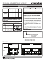
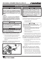
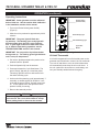
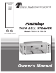
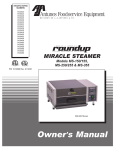
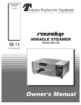
MANUFACTURING
NUMBERS:
9100400
9100402
9100410
9100412
�
L IS
T ED
��
AN
TACO BELL STEAMER
I T A T IO
L IS
N
S
T ED
��
Models TBS-1X & TBS-2X
P/N 1010698 Rev. E 03/04
Owner ’s Manual
TACO BELL STEAMER TBS-2X & TBS-1X
TABLE OF CONTENTS
Owner Information .....................................................2
General......................................................................2
Warranty Information .................................................2
Service/Technical Assistance ....................................3
Model Designation.....................................................3
Manufacturing Number ..............................................3
Important Safety Information ....................................4
Electrical Ratings.......................................................6
Dimensions................................................................6
Electrical Cord & Plug Configurations .......................6
Specifications .............................................................6
Capacities..................................................................6
Installation...................................................................7
Unpacking..................................................................7
Equipment Setup .......................................................7
Operation.....................................................................9
Operating Instructions ............................................ 10
Daily Cleaning .........................................................11
Monthly Maintenance ............................................. 12
Troubleshooting .......................................................14
Optional Water Pressure Regulator Kit - Part No.
7000314 .....................................................................16
Wiring Diagram.........................................................16
Replacement parts ...................................................17
NOTES .......................................................................19
LIMITED WARRANTY ...............................Back Cover
OWNER INFORMATION
The warranty does not extend to:
General
• Damages caused in shipment or damage as
result of improper use.
The Taco Bell Steamer produces steam using plain tap
water for quick heating and reconstituting of food items.
Simple push-button action delivers a fully adjustable
impulse of steam. Because the amount of steam is
consistent, it removes the guesswork and produces a
uniform finished product from one operator to another.
• Installation of electrical service.
• Installation of plumbing or water supply, or
water pressure regulator (if applicable).
This manual provides the safety, installation and operating procedures for the Taco Bell Steamer. We recommend that all information contained in this manual
be read prior to installing and operating the unit.
• Calibration, adjustment or maintenance.
• Normal maintenance as outlined in this
manual.
Your Taco Bell Steamer is manufactured from the finest materials available and is assembled to Roundup’s
strict quality standards. This unit has been tested at
the factory to ensure dependable trouble-free operation.
• Consumable parts such as gaskets, rubber
feet, labels, O-rings, etc.
Warranty Information
• Damage caused by abuse or careless handling.
• Malfunction resulting from improper maintenance or improper/incorrect voltage supply.
Please read the full text of the Limited Warranty
printed on the back cover of this manual.
• Damage from moisture into electrical
components.
If the unit arrives damaged, contact the carrier
immediately and file a damage claim with them.
Save all packing materials when filing a claim.
Freight damage claims are the responsibility of the
purchaser and are not covered under warranty.
• Damage from tampering with, removal of, or
changing any preset control or safety device.
IMPORTANT! Keep these instructions for future reference. If the unit changes ownership, be sure this manual accompanies the equipment.
2
P/N 1010698 Rev. E 03/04
TACO BELL STEAMER TBS-2X & TBS-1X
OWNER INFORMATION (continued)
Service/Technical Assistance
Authorized Service Agency
If you experience any problems with the installation
or operation of your unit, contact your local Roundup
Authorized Service Agency. They can be found in the
service agency directory packaged with the equipment.
Name:
Phone No.:
Address:
Fill in the information below and have it handy when
calling your authorized service agency for assistance.
The serial number is on the specification plate located
on the side of the unit.
Use only genuine Roundup replacement parts in this
unit. Use of replacement parts other than those supplied by the manufacturer will void the warranty. Your
Authorized Service Agency has been factory trained
and has a complete supply of parts for this unit.
Purchased From:
You may contact the factory at 1-877-392-7854 or 1630-784-1000 outside the United States if you have
trouble locating your local authorized service agency or
need technical assistance.
Date of Purchase:
Model No.:
Serial No.:
Mfg. No.:
Refer to the service agency directory and fill in the
information below:
A.J. Antunes & Co. reserves the right to change specifications and product design without notice. Such revisions do not
entitle the buyer to corresponding changes, improvements, additions or replacements for previously purchased equipment.
P/N 1010698 Rev. E 03/04
3
TACO BELL STEAMER TBS-2X & TBS-1X
IMPORTANT SAFETY INFORMATION
Throughout this manual, you will find the following safety words and symbols that signify important safety
issues with regards to operating or maintaining the equipment.
WARNING
WARNING
GENERAL WARNING. Indicates information important to the proper operation of
the equipment. Failure to observe may
result in damage to the equipment and/or
severe bodily injury or death.
ELECTRICAL WARNING. Indicates information relating to possible shock hazard.
Failure to observe may result in damage
to the equipment and/or severe bodily
injury or death.
CAUTION
WARNING
GENERAL CAUTION. Indicates information important to the proper operation of
the equipment. Failure to observe may
result in damage to the equipment.
HOT SURFACE WARNING. Indicates
information important to the handling of
equipment and parts. Failure to observe
caution could result in personal injury.
In addition to the warnings and cautions in this manual,
use the following guidelines for safe operation of the
unit.
The following warnings and cautions appear
throughout this manual and should be carefully
observed.
• Turn the unit off, disconnect the power source
and allow unit to cool down before performing
any service or maintenance on the unit.
• Read all instructions before using equipment.
• For your safety, the equipment is furnished with
a properly grounded cord connector. Do not
attempt to defeat the grounded connector.
• The procedures in this chapter may include
the use of chemical products. These chemical products will be highlighted with bold
face letters followed by the abbreviated HCS
(Hazard Communication Standard). See
Hazard Communication Standard manual for
the appropriate Material Safety Data Sheets
(MSDS).
• Install or locate the equipment only for its intended use as described in this manual. Do not use
corrosive chemicals in this equipment.
• Do not operate this equipment if it has a damaged cord or plug, if it is not working properly, or
if it has been damaged or dropped.
• The equipment should be grounded according to local electrical codes to prevent the
possibility of electrical shock. It requires a
grounded receptacle with separate electrical
lines, protected by fuses or circuit breaker of
the proper rating.
• This equipment should be serviced by qualified
personnel only. Contact the nearest Authorized
Service Agency for adjustment or repair.
• Do not block or cover any openings on the unit.
• Do not immerse cord or plug in water.
• All electrical connections must be in accordance with local electrical codes and any
other applicable codes.
• Keep cord away from heated surfaces.
• Do not allow cord to hang over edge of table or
counter.
4
P/N 1010698 Rev. E 03/04
TACO BELL STEAMER TBS-2X & TBS-1X
IMPORTANT SAFETY INFORMATION (continued)
• WARNING ELECTRICAL SHOCK HAZARD.
FAILURE TO FOLLOW THESE INSTRUCTIONS
COULD RESULT IN SERIOUS INJURY OR
DEATH.
-
Electrical ground is required on this appliance.
-
Do not modify the power supply cord plug.
If it does not fit the outlet, have a proper
outlet installed by a qualified electrician.
-
Do not use an extension cord with this
appliance.
-
Check with a qualified electrician if you
are in doubt as to whether the appliance is
properly grounded.
• To ensure proper steaming characteristics,
some mineral deposits must be present on
generator surface. If, during cleaning, the
surface does become free of mineral deposits,
add plain tap water to surface and allow it boil
off. This will ensure proper steaming characteristics by creating a thin layer of mineral
deposits on the casting.
• Chlorides or phosphates in cleansing agents
(e.g. bleach, sanitizers, degreasers or detergents) could cause permanent damage to
stainless steel equipment. The damage is
usually in the form of discoloration, dulling
of metal surface finish, pits, voids, holes or
cracks. This damage is permanent and not
covered by warranty:
• This equipment is to be installed to comply with the basic plumbing code of the
Building Officials and Code Administrators,
Inc. (BOCA) and the Food Service Sanitation
Manual of the Food and Drug Administration
(FDA).
The following tips are recommended for maintenance of your stainless steel equipment,
• Water pressure must not exceed 30 psi (2.1
kg/cm2 or 207 kPa). Higher water pressures
may cause poor performance or flooding.
To reduce water pressure, install a water
pressure regulator and set water pressure
between 20-30 psi (1.4 - 2.1 kg/cm2 or 138
- 207 kPa). To order a water pressure regulator from your authorized service center, order
Roundup part number 7000314.
• Do not clean this appliance with a water jet.
• Do not use a sanitizing solution or abrasive
materials. The use of these may cause damage to the stainless steel finish.
P/N 1010698 Rev. E 03/04
5
-
Always use soft, damp cloth for cleaning,
rinse with clear water and wipe dry. When
required, always rub in direction of metal
polish lines.
-
Routine cleaning should be done daily
using soap, ammonia detergent and water.
-
Stains and spots should be sponged using
a vinegar solution as required.
-
Finger marks and smears should be
rubbed off using soap and water.
-
Hard water spots should be sponged using
a vinegar solution.
TACO BELL STEAMER TBS-2X & TBS-1X
SPECIFICATIONS
Electrical Ratings
Model and
Manufacturing
Number
Voltage
Watts
Amps
Hertz
TBS-2X
9100400
(per side)
208
3300
15.9
50/60
TBS-1X
9100410
208
3300
15.9
50/60
WARNING
All electrical connections must be in accordance
with local electrical codes and any other applicable codes.
WARNING
ELECTRICAL SHOCK HAZARD.
FAILURE TO FOLLOW THE INSTRUCTIONS IN
THIS MANUAL COULD RESULT IN SERIOUS
INJURY OR DEATH.
CAUTION
The TBS-2X has two power cords. Connect each
plug to a receptacle that is connected to an individual circuit.
• Electrical ground is required on this appliance.
• Do not modify the power supply cord plug. If
it does not fit the outlet, have a proper outlet
installed by a qualified electrician.
Electrical Cord & Plug Configurations
Letter
Code*
Description
Configuration
C
Commercial Cord
(C)V**
6-20P, 20 Amp., 250
VAC., Non – Locking
(Assembly Only).
• Do not use an extension cord with this appliance.
• Check with a qualified electrician if you are in
doubt as to whether the appliance is properly
grounded.
Model Designation
* Used in Model Designation
** Indicates that the plug comes with a Commercial Cord.
TBS-2X
Single or Dual Capacity
1 = Single Chamber
2 = Dual Chamber
Capacities
• TBS-1X: one Taco Bell product
• TBS-2X: two Taco Bell products
Dimensions
��������
���� ���
�������
���� ���
�����
�����
��������
���� ���
�����
�����
��������
��������
�����
�����
6
�����
�����
�������
�������
�����
�����
P/N 1010698 Rev. E 03/04
TACO BELL STEAMER TBS-2X & TBS-1X
INSTALLATION
Unpacking
CAUTION
All electrical connections must be in accordance
with local electrical codes and any other applicable codes.
1. Remove unit and all packing materials from shipping carton.
2. The box should contain the following:
• Taco Bell Steamer
• Handle & Handle Guard (Qty. 2 for TBS-2X)
• Water Quick Disconnect Kit
(Qty. 2 for TBS-2X)
• Water Measuring & Calibration Kit
Liner
Guard
NOTE: If any parts are missing or damaged, contact Antunes Technical Service IMMEDIATELY at
1-877-392-7854 or 1-630-784-1000.
Handle
Spatula
3. Remove all packing materials and protective coverings from the unit.
Figure 1. Assembling
4. Remove and wash the spatula(s) and liner(s) in
soap and water. Rinse with clean hot water and
allow to air dry.
ELECTRICAL
1. Place the unit on a sturdy, level table or other
work surface. Turn off the Rocker Switch (power
On/Off) before proceeding.
5. Wipe all surfaces of the unit with a hot damp
cloth.
2. Connect the unit to the power supply.
NOTE: Do not use a dripping wet cloth. Wring out
before use.
CAUTION
The TBS-2X has two power cords. Connect each
plug to a receptacle that is connected to an individual circuit.
6. Assemble the handle and handle guard to the
spatula(s) as shown in Figure 1.
7. Re-install spatula(s).
Equipment Setup
GENERAL
When placing the unit into service, pay attention to the
following guidelines:
• Make sure power to the unit is off and the unit is
at room temperature.
• Do not block or cover any openings on the unit.
• Do not immerse cord or plug in water.
• Keep cord away from heated surfaces.
• Do not allow cord to hang over edge of table or
counter.
P/N 1010698 Rev. E 03/04
7
TACO BELL STEAMER TBS-2X & TBS-1X
INSTALLATION (continued)
CAUTION
Water pressure must not exceed 30 psi (2.1 kg/
cm2 or 207 kPa). Higher water pressures may
cause poor performance or flooding. To reduce
water pressure, install a water pressure regulator, and set water pressure between 20-30 psi (1.4
- 2.1 kg/cm2 or 138 - 207 kPa). To order a water
pressure regulator from your authorized service
center, order Roundup part no. 7000314.
WARNING
ELECTRICAL SHOCK HAZARD.
BE SURE TO READ ALL INFORMATION AND FOLLOW ALL SAFETY PROCEDURES IN THE IMPORTANT SAFETY INFORMATION SECTION OF THIS
MANUAL BEFORE PERFORMING ANY OF THESE
STEPS.
PLUMBING
IMPORTANT: Taco Bell Corporation REQUIRES
installation of a Water Demineralizer system for
supplying water to this equipment. To purchase
the water filtration system, contact the approved
equipment distributor.
CALIBRATION
A Water Measuring and Calibration Kit is supplied with
your unit and consists of the following items:
• Two 24” Teflon tubes
• One Measuring Cup
CAUTION
This equipment is to be installed to comply with
the basic plumbing code of the Building Officials
and Code Administrators, Inc. (BOCA) and the
Food Service Sanitation Manual of the Food and
Drug Administration (FDA).
CAUTION
This procedure exposes hot surfaces. Use
extreme care when performing procedure as to
avoid personal injury.
1. Turn the Rocker Switch (power On/Off) to the
OFF position and allow the unit to cool down
before proceeding.
CAUTION
Connect this unit to COLD WATER SUPPLY LINE
ONLY. Connecting this unit to a hot water supply
line will VOID THE WARRANTY!
2. Remove the Top Cover, Generator Cover, and
Diffuser Plate (Figure 4).
NOTE: Flexible tubing (not supplied) for water
hookup should be a minimum 1/4”1 (6.5 mm) I.D.
3. Insert the slanted end of the Calibration Tube into
Steam Generator hole and push in fully (Figure 5).
1. Connect the flexible tubing to the quick disconnect insert using the supplied hose clamp.
NOTE: If tube will not push in easily, the hole could
be clogged with mineral deposits. Use a flat-bladed
screwdriver to scrape deposits out of the holes.
2. Push the Quick Disconnect Insert into the female
fitting on the back of the unit until it clicks
(Figure 2).
4. Put other end of calibration tubes into the calibration cup (Figure 6).
IMPORTANT: The TBS-2X has two fittings on the
back of the unit; one for each side.
Quick Disconnect Insert (provided)
5. Turn the Rocker Switch (power On/Off) to ON.
6. Press the Cycle Start button and operate the unit
through two complete cycles to purge all air from
the tubes.
Hose
(not
included)
NOTES: Water may come out of the calibration
tubes with force. Hold the tubes and cup firmly.
7. Empty all water from the cup, then reinsert the
tubes back into the cup. Press the Cycle Start
button to run one cycle. The cup should contain
0.8 oz (25 ml or 25 cc) water. If the cup contains
more or less than this amount, proceed to Step 8.
Figure 2. Connecting Water Supply (back of unit)
8
P/N 1010698 Rev. E 03/04
TACO BELL STEAMER TBS-2X & TBS-1X
INSTALLATION (continued)
NOTE: If steamer does not steam properly after calibration, refer to the Troubleshooting section of this
manual.
8. With the unit positioned at the edge of its location
surface (Edge of the counter, table, etc.) slide the
steamer forward approximately 3” to expose the
Water Volume Control on the button of the unit
(Figure 7).
NOTE: If the Calibration Kit is missing, use the
Calibration Chart (Figure 8) to figure the approximate volume. Turn the water volume control to
0. Determine your water pressure and locate it on
the chart (left side), then look to the right to find
the volume closest to 0.8 oz. (25 ml or 25 cc). Turn
adjustment clockwise to setting shown at top of
chart.
9. Using a small screwdriver (Figure 7), carefully and
slowly adjust the control clockwise to increase or
counterclockwise to decrease the amount of water
volume used per cycle.
10. Repeat steps 7 through 9 until the proper amount
of water level in the club is achieved.
Technical Theory of Operation
OPERATION
the Operation section of this manual.
An audio signal will sound for 3 seconds at the end of
a steaming cycle. If the heating circuit continues to call
for heat and the Generator overheats, an automatic
reset Hi-Limit will trip and open both the Generator and
Transformer circuits. The Hi-Limit will reset automatically once the Generator cools down.
When the Rocker Switch (power On/Off)is ON, line voltage flows to the primary side of the step down transformer. The transformer’s secondary side supplies 12
and 24 VAC to the Control Board. Once powered and
provided that the Generator’s temperature is below 380
F (193 C), the Control Board calls for heat by supplying
7-10 VCD to Solid State Relay terminals 3 (+) 4 (-).
NOTE: If this condition should repeat, the root
cause must be determined and corrected.
Once powered, the relay closes terminals 1 and 2,
which allows line voltage to flow to the Generator. As
the Generator heats up, a type “J” Thermocouple monitors the internal Generator temperature. As the heat
continues to increase, so does the Thermocouple’s DC
milivolts. Once the Generator temperature pproaches
380-420 F (193-215 C), the Thermocouple is generating
approximately 12 - 12 DC millivolts.
LED Layout
This section describes the four LEDs used by the system for status and diagnostic purposes.
•
The Control Board receives these millivolts and then
removes the 7-10 VDC to the Solid State Relay, since
the heating circuit has now become satisfied. Then,
terminals 1 and 2 of the Solid State Relay open and the
Generator stops heating.
When off, this LED indicates that the Generator is
up to operating temperature.
•
The heating circuit will cycle on and off as needed,
even at idle. When the cycle start (momentary) button is pressed, it signals the Control Board to initiate a
steam cycle. The Control Board then supplies 24 VAC
to the Solenoid Valve for a split second. The Solenoid
valve opens, and allows approximately 3/4 - 1 ounce
(4-5 tablespoons) of water to be disbursed onto the
Generator Surface for steaming.
CR7 GREEN (Solenoid Valve): When lit, this LED
indicates that the Control Board is supplying 24
VAC to the Solenoid Valve.
NOTE: This LED is only lit for a split second.
Since the Generator has an oval cover that is secured
in place with a wing nut, the steam is forced downward
throught the Generator steam ports and onto the
product.
•
CR8 YELLOW (Audio): When lit, this LED indicates that the Control Board is supplying 10 VDC
to the audio signal. The audio signal and LED will
activate for 3 seconds at the completion of a steam
cycle.
•
CR10 YELLOW (Thermocouple): When lit, this
LED indicates that the Thermocouple is disconnected or “open” and the Control Board will not call
for heat.
NOTE: This LED should NOT be lit during normal
operation.
The Control Board incorporates several LEDs for
status and diagnostic purposes. See “LED Layout” in
P/N 1010698 Rev. E 03/04
CR6 RED (Heat): When lit, this LED indicates that
the Control Board is calling for heat by supplying 710 VDC to the Solid State Relay.
9
TACO BELL STEAMER TBS-2X & TBS-1X
OPERATION (continued)
Operating Instructions
IMPORTANT: Steam generator must be calibrated
before initial use. See the section titled Calibration
in the Installation section of this manual.
�����
Rocker Switch
(Power On/Off)
1. Turn on the Rocker Switch (power On/Off)
(Figure 3).
��
2. Allow the unit to preheat for approximately 20-30
minutes.
�����
IMPORTANT: The green light will flash during warm-up. The flashing green ready light will
become steady when the unit is up to temperature. If green light continues to flash after warmup, or starts to flash during operation, see the
TROUBLESHOOTING section in this manual.
��������
Yellow Steaming Light
Cycle Start
Button
�����
�����
IMPORTANT: Do not push the Cycle Start button
during warm-up. The flashing green light indicates
unit is not up to temperature.
Green Ready Light
Figure 3. Operating Controls
Hi-Limit Thermostat
A hi-limit thermostat will turn off electrical power to the
generator and Transformer circuits if the unit overheats.
Turn unit off and allow to cool; the hi-limit thermostat
will automatically reset when the unit cools down. If
the unit continues to shut off due to overheating, contact your Roundup authorized service agency.
3. Pull out the Spatula and place the product to be
steamed onto the Spatula.
4. Push the Spatula fully into the steamer.
5. Press and release the Cycle Start button The
green “Ready” light will go out and the yellow
“Steaming” light will come on and remain lit for
the entire steaming cycle.
6. At the end of the steaming cycle (approximately 7
seconds), an audible signal will sound for 3 seconds and the green “Ready” light will come back
on. These signals inform the operator that the
product is ready for serving.
7. Remove the steamed product.
WARNING
To avoid injury, use caution when pulling spatula
out from unit. Be sure to allow steam to escape
before putting hands or face over the steamer.
10
P/N 1010698 Rev. E 03/04
TACO BELL STEAMER TBS-2X & TBS-1X
MAINTENANCE
WARNING
Turn the unit off, disconnect the power source
and allow the unit to cool down before performing
any service or maintenance on the unit. The TBS2X has two power cords. Make sure both cords
are disconnected.
Chimney
Top Cover
CAUTION
Chlorides or phosphates in cleansing agents
(e.g. bleach, sanitizers, degreasers or detergents)
could cause permanent damage to stainless steel
equipment. The damage is usually in the form of
discoloration, dulling of metal surface finish, pits,
voids, holes or cracks. This damage is permanent
and not covered by warranty. The following tips
are recommended for maintenance of your stainless steel equipment:
Spatula
Generator
Cover
Wing Nut
Diffuser
• Always use soft, damp cloth for cleaning, rinse
with clear water and wipe dry. When required,
always rub in direction of metal polish lines.
Steam
Ports
• Routine cleaning should be done daily using
soap, detergent, and water.
Liner
• Stains and spots should be sponged using a
vinegar solution.
Steam Generator
• Finger marks and smears should be rubbed off
using soap and water.
Figure 4. Steamer Components
Daily Cleaning
• Hard water spots should be sponged using a
vinegar solution.
1. Turn the Rocker Switch (power On/Off) to OFF,
unplug the power cord(s), and allow the unit to
cool down before proceeding.
CAUTION
Do not use a sanitizing solution or abrasive materials. The use of these may cause damage to the
stainless steel finish.
2. Check the water quick disconnect fitting and all
hose clamp connections for leakage. If leakage
is apparent, tighten all clamps or replace part if
required.
3. Remove the Top Cover, Spatula(s), and Liner(s)
(Figure 4).
CAUTION
If a chemical cleaner is used, be sure it is safe to
use on cast aluminum. Observe all precautions
and warnings on product label.
4. Remove Chimney from rear of unit by sliding
upward and away from unit (Figure 4). Clean the
Top Cover, Spatula(s), Liner(s), and chimney in
hot soapy water, rinse in clear water and wipe
dry.
NOTE: Frequency of cleaning is determined by
water conditions, usage, and water filter systems.
5. Clean the chamber(s) of any product spills.
6. Clean entire unit with a clean, hot, damp cloth
(not dripping wet) and wipe dry.
7. Re-install chimney, liner(s) and spatula(s) and
Top Cover.
P/N 1010698 Rev. E 03/04
11
TACO BELL STEAMER TBS-2X & TBS-1X
MAINTENANCE (continued)
Monthly Maintenance
10. Clean Steam Chamber free of any product spills.
Your steamer utilizes an open steam generator. Water
sprayed onto the generator surface flashes into steam
immediately, but the minerals in the water do not
steam; they stay on the generator surface. A small
amount of mineral deposits are needed for proper
operation, but a build-up of excessive mineral deposits
causes poor steaming efficiency, excessive moisture
(wet steam) and will eventually severely retard the
steaming action completely.
11. Clean unit surface with a hot, clean, damp cloth
(not dripping wet) and wipe dry.
12. Re-install all parts and fasten the generator
cover.
IMPORTANT: To ensure proper steaming characteristics, some mineral deposits must be present
on generator surface. If during cleaning, the surface does become free of mineral deposits (bare
aluminum), add plain tap water to surface and
allow to boil off.
CLEANING STEAM GENERATOR
1. Turn the Rocker Switch (power On/Off) to OFF,
unplug the power cord(s), and allow the unit to
cool down before proceeding.
IMPORTANT: In soft water areas, it may be necessary to add a small amount of lime to generator
surface to “season” it. This will ensure proper
steaming characteristics by producing a thin coating of mineral deposits on the surface. Seasoning
mixture consists of 75 ml. baking soda, 75 ml. lime,
and 1 gallon water. Pour 1/4” deep of seasoning
mixture onto hot generator. After mixture is converted to steam, the remaining loose powder can
be removed.
2. Remove Top Cover from unit.
3. Remove wing nut and Generator cover (Figure 4).
4. Remove Steam Diffuser.
5. Examine all Generator steam ports (Figure 4). If
mineral deposits have formed, place a flat blade
screwdriver or wire brush into openings. Use a
twisting motion to scrape openings clean.
13. Plug in power cord(s) and water line(s).
NOTE: If the mineral deposits come off in “flakes”
or in layers, build-up is excessive.
CALIBRATION
A Water Measuring and Calibration Kit is supplied with
your unit and consists of the following items:
• Two 24” Teflon tubes
• One measuring cup
WARNING
This procedure exposes hot surfaces. Use
extreme care when performing procedure to avoid
personal injury.
6. Use a brass or stainless steel wire brush and
small scraper to loosen and remove excessive
deposits from the generator surface. If deposits
are still excessive and/or difficult to remove, go to
Step 7.
7. Pour delimer solution (not supplied) onto the
generator surface. Be sure to follow the delimer
manufacturer’s directions for proper mixture and
use; it must be safe to be used on aluminum.
1. Turn the Rocker Switch (power On/Off) to OFF
and allow the unit to cool down before
proceeding.
CAUTION
If a chemical cleaner/delimer is used, be sure it is
safe to use on cast aluminum. Observe all precautions and warnings on the product label.
2. Remove the Top Cover, Generator Cover, and
Diffuser Olate (Figure 4).
3. Insert the slanted end of the calibration tube into
steam generator hole and push in fully (Figure 5).
8. Remove the delimer solution from the generator
and rinse with clear water to remove traces of
delimer.
NOTE: If tube will not push in easily, the hole could
be clogged with mineral deposits. Use a flat-bladed screwdriver to scrape deposits out of the holes.
9. Clean the following parts in hot, detergent water,
then rinse in clear water and wipe dry:
• Spatula
• Liner
• Chimney
• Diffuser
4. Put other end of calibration tubes into the calibration cup (Figure 6).
• Top Cover
• Generator Cover
12
P/N 1010698 Rev. E 03/04
TACO BELL STEAMER TBS-2X & TBS-1X
MAINTENANCE (continued)
Slanted end of tube
��
��
�
��
��
�
���
��
���
��
���
���
��
CA
U
T
"H ION
OT
"
��
��
CA
UTI
"H ON
OT"
��
�
��
�
���
��
���
��
���
���
��
Figure 5. Installing Calibration Tubes
Figure 6. Water Measurement
5. Turn the Rocker Switch (power On/Off) to ON.
6. Press the Cycle Start button and operate the unit
through two complete cycles to purge all air from
the tubes.
��
�����
��
�
��
��
��
�
�
The cup should contain 0.8 oz. (25 ml or 25 cc).
If cup contains more or less of this amount, proceed to Step 8.
�
� � ��
�
7. Empty all water from the cup, then reinsert the
tubes back into the cup. Press the Cycle Start
button to run one cycle.
�
��
����
�
�� � �
� �� �
��
NOTE: Water may come out of the calibration
tubes with force. Hold the tubes and cup firmly.
8. With the unit positioned at the edge of its location
surface (edge of the counter, table, etc.) slide the
steamer forward approximately 3” to expose the
Water Volume Control on the bottom of the unit
(Figure 7).
CAUTION
Excessive force will damage this control. Do not
turn past built-in stops on the control or damage to
the unit will occur and void the warranty.
9. Using a precision flat blade screwdriver, carefully and slowly adjust the control clockwise to
increase or counterclockwise to decrease the
amount of water used per cycle.
Figure 7. Water Volume Adjustment
���
�
Water Pressure
NOTE: If steamer does not steam properly after
calibration, refer to the Troubleshooting section of
this manual.
NOTE: If calibration kit is missing, use the
Calibration Chart (Figure 8) to figure approximate volume. Turn the water volume control to
0. Determine your water pressure and locate it on
the chart (left side), then look to the right to find
the volume closest to 0.8 oz. (25 ml or 25 cc). Turn
adjustment clockwise to setting shown at the left of
chart.
���
Water Volume Adjustment
�
����
�
10. Repeat steps 7 - 9 until the proper amount of
water level in the cup is achieved.
P/N 1010698 Rev. E 03/04
��
�
�
�
���
�
�� ��
���
0
1/4
1/2
3/4
15 psi
–
10 ml
20 ml 25 ml
32 ml
20 psi
–
15 ml
23 ml 30 ml
37 ml
30 psi
–
16 ml
27 ml 35 ml
48 ml
35 psi
5 ml
20 ml
30 ml 40 ml
50 ml
35 psi
7 ml
21 ml
32 ml 42 ml
55 ml
40 psi
9 ml
22 ml
37 ml 45 ml
60 ml
Figure 8. Calibration Chart
13
MAX
TACO BELL STEAMER TBS-2X & TBS-1X
TROUBLESHOOTING
WARNING
To avoid possible personal injury and/or damage to the unit, inspection, test and repair of electrical equipment should be performed by qualified service personnel. The unit should be unplugged when servicing,
except when electrical tests are required. Use extreme care during electrical circuit tests. Live circuits will
be exposed. If the troubleshooting steps listed do not solve your machine problem, contact an Authorized
Service Agency for further assistance.
Problem
Unit steams, but
requires 2 or more
cycles to melt cheese.
Possible Cause(s)
Corrective Action
Generator surface temperature is too
low
Verify Generator surface temperature to be 380420°F.
Insufficient or excessive calcium
deposits on Generator surface.
Verify Generator surface has a thin calcium
coating for proper steaming. Refer to the
Maintenance section of this manual.
Generator Cover is warped or loose.
Verify that the Generator Cover wingnut is tight.
If noticable steam excapes around the Generator
Cover, replace the Generator Cover.
Low water pressure.
Verify Water Pressure regulator is set to 20-30
psi, adjust accordingly.
Water Volume Adjustment is set too
low.
Calibrate unit for proper water volume. Refer to
the Maintenance section of this manual.
Generator Steam Ports are restricted. Verify that the Steam Ports are not restricted.
Clean accordingly.
Unit heats but does not
steam.
Generator surface is bare.
Generator surface must have a thin calcium
coating for proper steaming. Refer to the
Maintenance section of this manual.
Low or no water pressure in water
line.
Remove the Quick Disconnect Insert from the
rear of the unit. While holding into an empty
cup, press the white plastic tip. Strong steady
water flow should be noted. If so, re-engage
firmly into the unit. If not present, or low pressure, contact your maintenance person or
plumber.
Solenoid Valve Coil is “open.”
Verify that there are 8-20 Ohms on the coil.
Control Board inoperable or problem- Verify 24 VAC to Solenoid Valve Coil when the
atic.
Cycle Start button is pushed.
NOTE: Wires must be left attached to valve
and voltage is only read for a split second.
If there is no voltage, replace the Control Board
Quick Disconnect is not fully engaged Remove and re-engage the Quick Disconnect
at rear of unit or is damaged.
firmly until a “click” is heard. Replace if damaged.
Excessive condensation
in Food Compartment.
Cycle Start switch inoperable.
Verify continuity when the switch is pressed. If
there is no continuity replace the switch.
Water pressure is too high.
Verify Water Pressure Regulator is set to 20-30
psi, adjust accordingly.
Water Volume Adjustment is set too
high.
Calibrate unit for proper water volume. Refer to
the Maintenance section of this manual.
14
P/N 1010698 Rev. E 03/04
TACO BELL STEAMER TBS-2X & TBS-1X
TROUBLESHOOTING (continued)
Problem
Possible Cause(s)
Corrective Action
Solenoid Valve is leaking due
to debris trapped within its
plunger and seat.
Disassemble the Solenoid Valve and clean
out the plunger. Reassemble and test. If the
a leak is still present, replace the Solenoid
Valve.
Solenoid Valve is installed
incorrectly.
If the Solenoid Valve was replaced, verify
that the “IN” and “OUT” labels on the valve
correspond to the water flow.
Unit only leaks water when powered on.
Control Board inoperable or
problematic.
If 24 VAC is measured across the Solenoid
Valve Coil for over 2 seconds (with wires
still attached to the coil), replace the Control
Board.
No heat and the green ready light
flashes continuously.
Generator is “open.”
Verify that there are 13 Ohms for a 208 volt
generator and 17.5 Ohms for a 240 volt generator (plus or minus 1 Ohm). Replace if the
generator fails test.
Solid State Relay not closing.
Verify that there is 7-10 VDC on relay
terminals 3 (+) 4(-). If present, check for line
voltage across relay terminals 1 and 2.
If present, replace the relay.
Control Board inoperable or
problematic.
Verify that there is 7-10 VDC on terminals
T5 & T3. If not present, replace the Control
Board.
Loose, burnt, or broken wires
in heater circuit.
Repair or replace wires.
Circuit is wired incorrectly.
Verify that all wiring matches the Wiring
Diagram in this manual.
Unit only leaks water when powered off.
Unit does not operate, power switch Unit unplugged.
is on but light is off.
Circuit breaker is off.
Power Cord defective or inoperable.
Plug Power Cord into the appropriate outlet.
Reset the circuit breaker.
Check for continuity.
Power Switch defective or
inoperable.
Green “Ready” light and “Yellow”
steaming light turn on and off intermittently.
P/N 1010698 Rev. E 03/04
Hi-Limit is tripping because of
an overheating Generator.
Verify that the generator surface temperature is between 380-420° F. If the temperature is above 420° F, contact your maintenance person or Authorized Service Agency.
Hi-Limit is tripping prematurely.
If the Hi-Limit trips within 380-420° F,
replace the Hi-Limit thermostat.
15
TACO BELL STEAMER TBS-2X & TBS-1X
WIRING DIAGRAM
�����
����
����� ��� ����� �� �� �� ��� ���������
������ ��������� ����������
������ ������ �� ��� ���������
������ ������ �� ��� ���������
���
���
���
������ ������ �� ��� ���������
������ ������ �� ��� ���������
�������
�����
��
��������
�����
��
���
�������
��
��
� ��� �
��
�
�
�����������
��
�
������
���
� ��� �
�����
� ��� �
���
��
��
�
� ��� �
��������
����������
��
� ��� �
�
� ��� �
�
� ��� �
�
�
��������
���
�
� ��� �
�
� ��� �
�
� ��� �
��
� ��� �
�����
������
� ��� �
���
���
�
���������
������
������������
OPTIONAL WATER PRESSURE REGULATOR KIT - PART NO. 7000314
General: This kit protects your equipment from any foreign debris in the water line that could get into the food,
damage the unit’s solenoid (causing the unit to leak or
flood) and also prevents excessive and/or fluctuation
water pressure from interfering with the equipment’s
proper and consistent operation.
4
1
2
3
6
2
��
��
��
���
���
���
���
���
��
�
�
��
���
���
The 7000134 Regulator Kit consists of the
following items:
���
��
5
16
Ref.
Part No.
Description
Qty.
1
0503849
Bracket
1
2
2040130
Male Adapter, Barbed -1/4”
2
3
2090127
Strainer - 1/4 NPT
1
4
2170113
Regulator, Pressure
1
5
2170114
Gauge, Water Pressure
1
6
2190129
Nipple, 1/4 NPT x 1/4” NPT
1
7
2110104
Clamp, worm
drive (not shown)
2
8
1010790
Instruction sheet
(not shown)
1
P/N 1010698 Rev. E 03/04
TACO BELL STEAMER TBS-2X & TBS-1X
REPLACEMENT PARTS
�
�
��
��
��
��
�
�
�
��
�
�
��
��
��
��
�
�
��
��
��
��
��
��
��
��
��
��
��
�� ��
��
��
��
��
��
��
��
��
��
��
��
��
��
��
��
��
��
��
��
��
��
��
��
��
��
��
��
�
�
�
�
�
��
��
P/N 1010698 Rev. E 03/04
�� ��
17
��
TACO BELL STEAMER TBS-2X & TBS-1X
REPLACEMENT PARTS (continued)
Item
1
Part
No.
5
6
7
8
9
0011229
0011198
7000150
2100250
0503087
0503226
2100247
0503085
0503592
0300129
7000430
10
11
12
4010137
0021110
4060363
13
4060362
14
15
16
17
18
19
4010166
0503315
0020341
2100249
2100107
210K230
20
21
22
23
24
25
26
27
28
210K123
210K134
7000160
4050135
7000156
4040145
2000202
2000203
4030222
2190107
2080117
29
7000139
30
405K125
2
3
4
Description
Item
Qty.
TBS-1X TBS-2X
Top Cover Assy.
Top Cover Assy.
Calibration Kit
Guard, Knob, Top Cover
Cover, Control Housing
Cover, End Housing
Knob
Cover, Generator
Diffuser
Stud
Generator Kit,
(Incl. # 7, 8, 49, 56 &
Qty. 3 of 55 & Qty 2 of 27)
Rocker Switch, Power On/Off
Corner Filler
Indicator Light, Yellow,
(Steaming Light)
Indicator Light, Green
(Ready Light)
Switch, Cycle Start
Liner, Cavity
Spatula
Guard, Handle
Handle
Bumper Recess 1” Leg Kit
(Incl. parts for 4 legs)
4” Leg Kit (Incl 1 leg)
4” Leg Kit (Incl. 4 legs)
Control Board Kit
Thermocouple Assy.
Audio Alarm Kit
Solenoid Valve, 24 VAC
Tube, Inlet
Tube, Restrictor
Hi-limit Thermostat
Pipe, Teflon (see Note 2)
Connector,
Quick Disconnect Female
Connector,
Quick Disconnect Male
Relay, Solid State
1
1
1
1
1
1
1
1
1
31
32
33
35
1
1
2
2
2
2
2
2
1
1
4
2
2
4
1
2
1
1
1
1
1
1
2
2
2
2
2
2
1
4
1
1
1
1
1
1
1
1
2
1
4
1
2
2
2
2
2
2
2
4
1
2
1
1
2
2
Part
No.
36
37
4050180
0700452
040K251
0021133
0021136
0700554
7000136
38
39
40
41
42
43
44
45
46
47
48
49
50
100P967
2040146
2040145
7000319
0503093
1000975
0503171
2040103
308P103*
308P105*
308P104*
306P136*
306P123*
51
52
53
54
55
56
57
58
60
306P101*
308P143*
3048105*
300P102*
306P134
325P170*
020P117*
362P102*
7000299
Description
Qty.
TBS-1X TBS-2X
Heat Sink
Power Cord
Strain Relief
Chimney
Chimney
Wire Set (not shown)
Terminal Block Kit
(Includes 38, 50, & 51)
Label, Marking
Tee, Female
Elbow, Female
Transformer
Retainer, Thermocouple
Label, Control Panel
Bracket, Mounting
Valve Connector
Screw, #8-32 x 1/4”
Screw, #8-32 x 1/2”
Screw, #8-32 x 3/8”
Screw, #8-32 x 5/8”
Screw, Stainless Steel,
#6-32 x 7/8”
Nut, Hex, #6-32
Nut, Hex, KEPS, #8-32
Nut, Hex, Zinc, #4-40
Nut, Tinnerman, #8-32
Screw, #6-32 x 3/8”
Wingnut, Cast Iron, 1/4”-20
O-ring
Lock washer, Toothed
Nut (3-Pak) See Note 1
1
1
1
1
1
1
1
2
2
2
1
1
2
2
1
1
1
1
1
1
1
1
1
1
1
1
2
2
2
2
2
2
2
2
1
1
1
1
1
1
1
1
1
3
1
1
1
1
1
1
1
1
1
3
1
1
1
1
* Only available in packages of 10.
NOTE 1: This special wrench nut is required to
separate the stem from the solenoid valve on older
solenoid valves
NOTE 2: Always use Teflon® tape on threads and
tighten until very snug.
18
P/N 1010698 Rev. E 03/04
TACO BELL STEAMER TBS-2X & TBS-1X
NOTES
P/N 1010698 Rev. E 03/04
19
LIMITED WARRANTY
Equipment manufactured by A.J. Antunes & Co. Foodservice Equipment has been constructed of the finest materials available and
manufactured to high quality standards. These units are warranted to be free from mechanical and electrical defects for a period of
one year from date of purchase or 18 months from shipment from factory, whichever occurs first, under normal use and service, and
when installed in accordance with manufacturer’s recommendations.
To insure continued proper operation of the units, follow the maintenance procedure outlined in the Owner’s Manual.
1. This warranty does not cover cost of installation, defects caused by improper storage or handling prior to placing of the Equipment. This
warranty does not include overtime charges or work done by unauthorized service agencies or personnel. This warranty does not cover
normal maintenance, calibration, or regular adjustments as specified in operating and maintenance instructions of this manual, and/or labor
involved in moving adjacent objects to gain access to the Equipment. This warranty does not cover consumable items such as gaskets
and light bulbs, nor does it cover water contaminant problems such as foreign material in water lines or inside solenoid valves. It does not
cover water pressure problems or failures resulting from improper/incorrect voltage supply.
For the first 90 (ninety) days after installation (in USA only): The Melter will be repaired in-store (subject to terms of the limited Warranty)
by our Authorized Service Agency, at no charge for parts, labor, travel/mileage.
For the next 9 (nine) months of your warranty (12 months for all other countries): If the Melter is carried into an Authorized Service Agency,
it will be repaired (subject to the terms of the Limited Warranty) at no charge for parts and labor. If you request the Authorized Service
Agency to service the Melter at your store, the store must pay any charges above and beyond the “SHOP” labor rate for that Service Agency,
including travel/mileage charges.
2. Roundup reserves the right to make changes in design or add any improvements on any product. The right is always reserved to modify
equipment because of factors beyond our control and government regulations. Changes to update equipment do not constitute a warranty
charge.
3. If shipment is damaged in transit, the purchaser should make a claim directly upon the carrier. Careful inspection should be made of the shipment
as soon as it arrives and visible damage should be noted upon the carrier’s receipt. Damage should be reported to the carrier. This damage is
not covered under this warranty.
4. Warranty charges do not include freight or foreign, excise, municipal or other sales or use taxes. All such freight and taxes are the responsibility of the purchaser.
5. THIS WARRANTY IS EXCLUSIVE AND IS IN LIEU OF ALL OTHER WARRANTIES, EXPRESSED OR IMPLIED, INCLUDING ANY IMPLIED
WARRANTY OR MERCHANTABILITY OR FITNESS FOR A PARTICULAR PURPOSE, EACH OF WHICH IS HEREBY EXPRESSLY DISCLAIMED. THE REMEDIES DESCRIBED ABOVE ARE EXCLUSIVE AND IN NO EVENT SHALL ROUNDUP BE LIABLE FOR SPECIAL
CONSEQUENTIAL OR INCIDENTAL DAMAGES FOR THE BREACH OR DELAY IN PERFORMANCE OF THIS WARRANTY.
180 Kehoe
KehoeBlvd.
Blvd.
• Carol
Stream,
Illinois
60188
180
• Carol
Stream,
Illinois
60188
Telephone
(630) 784-1000
• FAX •(630)
784-1650
• 1-877-392-7854
Telephone
(630) 784-1000
FAX (630)
784-1650
www.ajantunes.com
Toll Free1-877-392-7854
(in the U.S.A. and Canada)
www.ajantunes.com