1
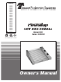
MANUFACTURING
NUMBERS:
9300300
9300302
9300304
9300306
9300308
9300309
9300320
9300321
9300322
9300324
9300330
9300331
9300332
9300334
9300336
9300376
9300340
9300341
9300342
9300344
9300350
9300351
9300352
9300356
9300360
9300374
9300376
9300380
�
L IS
T ED
��
N
S
I T A T IO
AN
L IS
T ED
HOT DOG CORRAL
Model HDC
Series 9300000
��
P/N 1010609 Rev. F 03/04
Owner ’s Manual
HOT DOG CORRAL
TABLE OF CONTENTS
Owner Information .....................................................2
General......................................................................2
Warranty Information .................................................2
Service/Technical Assistance ....................................3
Important Safety Information ....................................3
Electrical Ratings.......................................................5
Electrical Cord & Plug Configurations .......................5
Specifications .............................................................5
Capacities (Refrigerated Product Only–Not Frozen).5
Dimensions................................................................6
Unpacking..................................................................7
Equipment Setup .......................................................7
Installation...................................................................7
Food Shield (Optional) ..............................................8
Operation.....................................................................9
General......................................................................9
Operating Instructions ...............................................9
Cleaning ................................................................. 10
Maintenance..............................................................10
Inspecting and Aligning Drive Parts ....................... 10
Replacing the Black Nylon Glides ...........................11
Hot Dog Corral Technical Theory of Operation ...... 12
Technical Theory of Operation ...............................12
Troubleshooting .......................................................13
Replacement Parts ...................................................14
Wiring Diagrams.......................................................19
LIMITED WARRANTY................................................20
OWNER INFORMATION
General
Warranty Information
The Roundup Hot Dog Corral is a unique and innovative way to grill hot dogs. The hot dogs are placed in
a “corral” that moves up-and-down over a heated flat
grill surface. The corral motion allows the hot dogs to
turn. As the hot dogs turn, they roll in their own juices,
producing a self-basting hot dog that sears in all the
natural flavor.
Please read the full text of the Limited Warranty in this
manual.
The versatile Hot Dog Corral will accommodate any
size hot dog along with Polish sausage, bratwurst and
breakfast sausage.
The warranty does not extend to:
If the unit arrives damaged, contact the carrier immediately and file a damage claim with them. Save all
packing materials when filing a claim. Freight damage
claims are the responsibility of the purchaser and are
not covered under warranty.
• Damages caused in shipment or damage as
result of improper use.
This manual provides the safety, installation and operating procedures for the Hot Dog Corral. We recommend that all information contained in this manual be
read prior to installing and operating the unit.
• Installation of electrical service.
• Normal maintenance as outlined in this manual.
• Malfunction resulting from improper maintenance.
Your Hot Dog Corral is manufactured from the finest
materials available and is assembled to Roundup’s
strict quality standards. This unit has been tested at
the factory to ensure dependable trouble-free operation.
• Damage caused by abuse or careless handling.
• Damage from moisture into electrical
components
• Damage from tampering with, removal of, or
changing any preset control or safety device.
IMPORTANT! Keep these instructions for future reference.
If the unit changes ownership, be sure this manual accompanies the equipment.
2
P/N 1010609 Rev. F 03/04
HOT DOG CORRAL
OWNER INFORMATION (continued)
Service/Technical Assistance
Refer to the service agency directory included with your
unit.
If you experience any problems with the installation
or operation of your unit, contact your local Roundup
Authorized Service Agency.
Authorized Service Agency
Name:
Fill in the information below and have it handy when
calling your authorized service agency for assistance.
The serial number is on the specification plate located
on the unit.
Phone No.:
Address:
Use only genuine Roundup replacement parts in this
unit. Use of replacement parts other than those supplied by the manufacturer will void the warranty. Your
Authorized Service Agency has been factory trained
and has a complete supply of parts for this toaster.
Purchased From:
Date of Purchase:
Model No.:
Serial No.:
You may also contact the factory at 1-877-392-7854
(toll Free in the U.S.) or 630-784-1000 if you have trouble locating your local Authorized Service Agency.
Mfg. No.:
IMPORTANT SAFETY INFORMATION
Throughout this manual, you will find the following safety words and symbols that signify important safety
issues with regards to operating or maintaining the equipment.
WARNING
WARNING
GENERAL WARNING. Indicates information important to the proper operation of
the equipment. Failure to observe may
result in damage to the equipment and/or
severe bodily injury or death.
ELECTRICAL WARNING. Indicates information relating to possible shock hazard.
Failure to observe may result in damage
to the equipment and/or severe bodily
injury or death.
CAUTION
WARNING
GENERAL CAUTION. Indicates information important to the proper operation of
the equipment. Failure to observe may
result in damage to the equipment.
P/N 1010609 Rev. F 03/04
HOT SURFACE WARNING. Indicates
information important to the handling of
equipment and parts. Failure to observe
caution could result in personal injury.
3
HOT DOG CORRAL
IMPORTANT SAFETY INFORMATION (continued)
• WARNING ELECTRICAL SHOCK HAZARD.
FAILURE TO FOLLOW THESE INSTRUCTIONS
COULD RESULT IN SERIOUS INJURY OR
DEATH.
In addition to the warnings and cautions in this manual,
use the following guidelines for safe operation of the
unit.
• Read all instructions before using equipment.
• For your safety, the equipment is furnished with
a properly grounded cord connector. Do not
attempt to defeat the grounded connector.
• Install or locate the equipment only for its intended use as described in this manual. Do not use
corrosive chemicals in this equipment.
• Do not operate this equipment if it has a damaged cord or plug, if it is not working properly, or
if it has been damaged or dropped.
• This equipment should be serviced by qualified
personnel only. Contact the nearest Roundup
authorized service facility for adjustment or repair.
-
Electrical ground is required on this appliance.
-
Do not modify the power supply cord plug.
If it does not fit the outlet, have a proper
outlet installed by a qualified electrician.
-
Do not use an extension cord with this
appliance.
-
Check with a qualified electrician if you
are in doubt as to whether the appliance is
properly grounded.
• This equipment is to be installed to comply with the basic plumbing code of the
Building Officials and Code Administration,
Inc. (BOCA) and the Food Service Sanitation
Manual of the Food and Drug Administration
(FDA).
• Do not block or cover any openings on the unit.
• Do not immerse cord or plug in water.
• Keep cord away from heated surfaces.
• Do not clean this appliance with a water jet.
• Do not allow cord to hang over edge of table or
counter.
• Do not use a sanitizing solution or abrasive
materials. The use of these may cause damage to the stainless steel finish.
The following warnings and cautions appear
throughout this manual and should be carefully
observed.
• Chlorides or phosphates in cleansing agents
(e.g. bleach, sanitizers, degreasers or detergents) could cause permanent damage to
stainless steel equipment. The damage is
usually in the form of discoloration, dulling
of metal surface finish, pits, voids, holes or
cracks. This damage is permanent and not
covered by warranty.
• Turn the unit off, disconnect the power source
and allow unit to cool down before performing
any service or maintenance on the unit.
• The procedures in this chapter may include
the use of chemical products. These chemical products will be highlighted with bold
face letters followed by the abbreviated HCS
(Hazard Communication Standard). See
Hazard Communication Standard manual for
the appropriated Material Safety Data Sheets
(MSDS).
• The following tips are recommended for maintenance of your stainless steel equipment.
• The unit should be grounded according to
local electrical codes to prevent the possibility of electrical shock. It requires a grounded
receptacle with separate electrical lines, protected by fuses or circuit breaker of the proper rating.
• All electrical connections must be in accordance with local electrical codes and any
other applicable codes.
4
-
Always use soft, damp cloth for cleaning,
rinse with clear water and wipe dry. When
required, always rub in direction of metal
polish lines.
-
Routing cleaning should be done daily
using soap, ammonia detergent and water.
-
Stains and spots should be sponged
using a vinegar solution as required.
-
Finger marks and smears should be
rubbed off using soap and water.
-
Hard water spots should be sponged
using a vinegar solution.
P/N 1010609 Rev. F 03/04
HOT DOG CORRAL
SPECIFICATIONS
Electrical Ratings
Model
Voltage
Watts
Amps
Hertz
HDC-20
120
1000
8.3
50/60
230
1000
4.3
50/60
210
1000
8.3
50/60
230
1250
5.4
50/60
120
1500
12.5
50/60
230
1500
6.5
50/60
120
1750
14.5
50/60
230
1750
7.6
50/60
120
1750
14.5
50/60
230
1750
7.6
50/60
HDC-21A
HDC-30A
HDC-35A
HDC-50A
CAUTION
All electrical connections must be in accordance
with local electrical codes and any other applicable codes.
WARNING
ELECTRICAL SHOCK HAZARD. FAILURE TO
FOLLOW THE INSTRUCTIONS IN THIS MANUAL
COULD RESULT IN SERIOUS INJURY OR DEATH.
• Electrical ground is required on this appliance.
• Do not modify the power supply cord plug. If
it does not fit the outlet, have a proper outlet
installed by a qualified electrician.
• Do not use an extension cord with this appliance.
• Check with a qualified electrician if you are in
doubt as to whether the appliance is properly
grounded.
Electrical Cord & Plug Configurations
Letter
Code*
Description
C
Commercial Cord
H
Harmonized Cord
(H)C***
CEE 7/7, 16 Amp.,
250 VAC (Assembly
Only).
(C)F**
5-15P, 15 Amp., 120
VAC., Non – Locking
(Assembly Only).
G
Configuration
Capacities
(Refrigerated Product Only–Not Frozen)
Model
HDC-20
At One Time
4-to-a-pound 7” Hot Dogs
20
HDC-21A
���
HDC-30A
���
BS-1363
13 Amp,
250 VAC
5
350
4-to-a-pound 7” Hot Dogs
50
P/N 1010609 Rev. F 03/04
300
4-to-a-pound 7” Hot Dogs
35
HDC-50A
210
4-to-a-pound 7” Hot Dogs
30
HDC-35A
200
4-to-a-pound 7” Hot Dogs
21
���
Per Hour
500
HOT DOG CORRAL
SPECIFICATIONS (continued)
Dimensions
C
B
A
Model
Width (A)
Depth (B)
Height (C)
Shipping Weight
HDC-20
18-3/4”
(476 mm)
21”
(533 mm)
8-1/2”
(216 mm)
45 lbs.
(20 kg)
HDC-21A
22-7/8”
(581 mm)
15-1/4”
(387 mm)
7-1/4”
(184 mm)
38 lbs.
(17.2 kg)
HDC-30A
22-7/8”
(581 mm)
20-5/8”
(524 mm)
7-1/4”
(184 mm)
48 lbs.
(21.2 kg)
HCD-35A
33-3/8”
(848 mm)
15-1/4”
(387 mm)
7-1/4”
(184 mm)
54 lbs.
(24.5 kg)
HDC-50A
33-3/8”
(848 mm)
20-5/8”
(524 mm)
7-1/4”
(184 mm)
70 lbs.
(31.75 kg)
6
P/N 1010609 Rev. F 03/04
HOT DOG CORRAL
INSTALLATION
Unpacking
Driver Frame
1. Remove unit and all packing materials from shipping carton.
2. Open the large box. Remove all packing materials and protective coverings from the unit and
parts.
NOTE: If any parts are missing or damaged, contact Antunes Technical Service IMMEDIATELY at
1-800-253-2991.
3. Wash driver frame in soap and water. Wipe all
surfaces of the unit with a hot damp cloth.
NOTE: Do not use a dripping wet cloth. Wring out
before use.
4. Install driver frame onto unit.
Figure 1. Hot Dog Corral
Equipment Setup
CAUTION
All electrical connections must be in accordance
with local electrical codes and any other applicable codes.
When placing the unit into service, pay attention to the
following guidelines.
• Make sure power to the unit is off and the unit is
at room temperature.
WARNING
ELECTRICAL SHOCK HAZARD. FAILURE TO
FOLLOW THE INSTRUCTIONS IN THIS MANUAL
COULD RESULT IN SERIOUS INJURY OR DEATH.
• Do not block or cover any openings on the unit.
• Do not immerse cord or plug in water.
• Electrical ground is required on this appliance.
• Keep cord away from heated surfaces.
• Do not modify the power supply cord plug. If
it does not fit the outlet, have a proper outlet
installed by a qualified electrician.
• Do not allow cord to hang over edge of table or
counter.
• Place unit on a sturdy, level table or work surface.
• Do not use an extension cord with this appliance.
Ensure that the line voltage corresponds to the stated
voltage on the unit specification label.
• The unit should be grounded according to local
electrical codes to prevent the possibility of
electrical shock. It requires a grounded receptacle with separate electrical lines, protected by
fuses or circuit breaker of the proper rating.
Turn the Rocker Switch (power On/Off) to OFF.
Connect the unit to the power supply.
• Check with a qualified electrician if you are in
doubt as to whether the appliance is properly
grounded.
P/N 1010609 Rev. F 03/04
7
HOT DOG CORRAL
INSTALLATION (continued)
Food Shield (Optional)
Item
NOTE: Early style corrals do not have weldnuts
on inside of side covers. When installing the food
shield, jamnuts (5, figure 2) must be used.
1. Turn the Rocker Switch (power On/Off) to OFF
and unplug the power cord.
2. Assemble the hardware to the left and right cover
panels as shown in Figure 2.
3. If a non-pivoting food shield is desired, follow
Installation A. If a pivoting food shield is desired,
use Installation B.
Part
No.
1
2
3
4
2120121
3080158
3250104
3250169
5
325P135
6
1150104
Description
Spacer
Screw, Pan Hd., #8-32 x 5/8”
Washer, Flat, SS, 1/4”
Shoulder Bolt, Socket Hd.,
5/16 x 1/2”
Jamnut, 1/4-20
(early style units only)
Allen Wrench (not shown)
Qty.
2
2
2
4
4
1
Installation A–Non-pivoting
NOTE: SG-21 & SG-35 shown. SGH-20 uses
same mounting, but is shaped differently.
Install shoulder
bolts through all
mounting holes in
food shield.
5
1
Early style units do not
have a weldnut on the
inside of the panel and
must use a 1/4-20 hex
jamnut (P/N 325P125).
On early style panels
without weldnuts, it is
necessary to enlarge the
mounting holes to accept
the 1/4-20 shoulder bolts.
3
3
Installation B–Pivoting
2
Rear Pivot - Install
rear shoulder bolts
through mounting
holes in food shield.
Front of shield rests
on top of shoulder
bolts.
4
4
Front Pivot - Install
front shoulder bolts
through mounting
holes in food shield.
Rear of shield rests
on top of shoulder
bolts.
Figure 2. Optional Food Shield Components
8
P/N 1010609 Rev. F 03/04
HOT DOG CORRAL
OPERATION
General
Rocker Switch
(Power On/Off)
Volume, preference and experience will determine what
temperature setting is best for your operation. When
holding hot dogs for long periods of time, it is recommended to keep the setting under 160°F (71°C). This
may vary depending on the type of hot dog used and
the production rate required. If appearance of the hot
dog is deteriorating rapidly, reduce temperature setting.
As the hot dogs turn in their own juices, they become
self-basting, searing in all of the natural flavor. Excess
juices are allowed to collect in the lower lip at the front
of the grill. These juices can be absorbed with a paper
towel and discarded.
Rear
Thermostat
Control
Timer
(Some Models)
NOTE: The driver frame will accommodate almost
any diameter size hot dog or sausage up to 1-1/4”
(31.8 mm).
Figure 3. Controls
3. Timer: Set the timer by pressing the Start button
once. To change the timer, press and hold the
Start button.
Operating Instructions
1. Turn the rocker switch (power on/off) to the ON
position.
NOTE: The timer default setting is 8 minutes. The
timer range is 1 - 15 minutes.
2. Set the thermostat controls to the desired setting.
4. Allow 10-15 minutes as a warm-up period, then
place the hot dogs in the driver frame assembly.
NOTE: Hot Dog Corrals (except Model HDC-20)
have two separate heating zones–upper and lower.
Some custom models have left-to-right controls.
Each zone is controlled by a separate thermostat.
P/N 1010609 Rev. F 03/04
Front Thermostat
Control
9
HOT DOG CORRAL
MAINTENANCE
Inspecting and Aligning Drive Parts
CAUTION
Chlorides or phosphates in cleaning agents (e.g.
bleach, sanitizers, degreasers or detergents)
could cause permanent damage to stainless steel
equipment. The damage is usually in the form of
discoloration, dulling of metal surface finish, pits,
voids, holes or cracks. This damage is permanent
and not covered by warranty. The following tips
are recommended for maintenance of your stainless steel equipment:
If the Drive Frame does not move smoothly, or during a
Motor replacement, inspect and align the drive parts as
follows:
1. Turn the Rocker Switch (power On/Off) to OFF
and unplug the power cord.
2. Remove the right and left side Panel Covers.
• Always use soft, damp cloth for cleaning, rinse
with clear water and wipe dry. When required,
always rub in direction of metal polish lines.
3. Place a straightedge on the outside surface of
the Pivot Arm and Motor Arm (Figure 5). There
should be no gap between the Motor Arm and the
straightedge.
• Routine cleaning should be done daily using
soap, ammonia detergent and water.
• Stains and spots should be sponged using a
vinegar solution.
4. To remove any gap, loosen the setscrews on the
Pivot Arm and Motor Arm (Figure 4).
• Finger marks and smears should be rubbed off
using soap and water.
5. Tighten the Pivot Arm setscrew. Allow 3/32” (2.5
mm) of in/out motion on the crossover shaft/arm
• Hard water spots should be sponged using a
vinegar solution.
CAUTION
Failure to allow room for drive parts expansion
can cause binding during operation and may
cause early motor failure.
WARNING
Turn the unit off, disconnect the power source
and allow the unit to cool down before performing
any service or maintenance on the unit.
when tightening the setscrew. This will compensate for heat expansion in the parts.
6. Place the straightedge on the outer surface of the
Pivot Arm and Motor Arm. Position the Motor Arm
until no gap exists as shown in Figure 5.
WARNING
Do not use a sanitizing solution or abrasive materials. The use of these may cause damage to the
stainless steel finish.
7. Tighten the Motor Arm setscrew.
Cleaning
NOTE: Be sure setscrews are resting on the flat
surface of the shafts when tightening.
The unit requires a minimum amount of maintenance.
To ensure proper operation, clean the unit after every
use.
8. If the Drive Frame still does not move freely, loosen setscrew and remove the Motor Arm (Figure 4)
from the Motor Shaft.
1. Remove the Driver Frame (Figure 4) and soak in
hot detergent water and clean using a soft brush.
Rinse in clear water and dry with a clean, dry
towel. Verify that the Roller Rods rotate easily
and have side to side motion by testing them
with your fingers.
Grasp both Slide Bracket Pins (Figure 4) and
move them back and forth to try and determine
the source of the bind. It may be necessary to
adjust the height of the Slide Bracket (Figure 4).
Inspect the Drive Rollers, bearings, and Retaining
Rings for wear and replace if necessary.
2. Wash cooking surface with a sudsy cloth and
rinse with a clean, wet cloth.
NOTE: If any of the Drive Parts are replaced, repeat
steps 1 - 8.
9. Reinstall the right and left Side Panel Covers.
10
P/N 1010609 Rev. F 03/04
HOT DOG CORRAL
MAINTENANCE (continued)
HDC-21A/35A ONLY: Remove the four Retainer Rings
and glides (Figure 6). Install new glides and secure
with Retainer Rings.
Left Side Cover
Driver Roller
Driver Frame w/ Roller Rods
HDC-20/30A/50A ONLY: Using a small screwdriver, pry
the four glides up and out of the unit (Figure 6A). Push
the new glides into the unit.
Right Side Cover
Slide Bracket
with Pins
Crossover
Shaft
Retainer Ring
& Nylon Glide
(HDC-21A/35A
ONLY)
Motor Arm
w/ Setscrew
Motor Arm
& Pivot Arm
Connecting
Link
Motor
Shaft
Driver
Roller
Retaining Ring
Pivot Arm w/setscrew
Figure 4. Drive Components
Pivot
Arm
Inner
Wall
Motor Arm
& Pivot Arm
Connecting Link
Motor Arm
INCORRECT
Remove Gap
Straight Edge
CORRECT
No Gap
Figure 6. HDC-21A/35A ONLY
Nylon Glides (4)
Straight Edge
Figure 5. Aligning Drive Components
Replacing the Black Nylon Glides
The Black Nylon Glides allow the Driver Frame to slide
back and forth smoothly and also prevents it from
scratching the grill surface area.
Depending on the model, the glides are attached to the
Driver Frame or to the unit itself (See Figure 6 and 6A).
The glides eventually wear down with normal use
and will require replacement as needed.
NOTE: Failure to replace missing/worn glides will
result in permanent Grill Surface and Driver Frame
Damage, NOT covered by warranty.
P/N 1010609 Rev. F 03/04
Figure 6A. HDC-20/30A/50A ONLY
11
HOT DOG CORRAL
TECHNICAL THEORY OF OPERATION
Hot Dog Corral Technical Theory of
Operation
The heating circuit(s) will cycle on and off as needed,
even at idle. The hot dogs are placed between the
Roller Rods of the sliding Driver Frame Assembly. As
the Drive Motor runs, it operates a linkage system
which, in turn, operates the Driver Frame Assembly by
moving it up and down.
When the Rocker Switch (power On/Off) is ON, voltage
flows to the capillary bulb Thermostat(s), Drive Motor
Assembly, and to the Digital Timer.**
NOTE: HDC-20 units consist of a single thermostat that controls the entire grill area temperature. HDC21A/30A/35A/50A units consist of
2 Thermostats. The upper Thermostat controls
the upper grill area temperature and the lower
Thermostat controls the lower grill area temperature.
As the hot dogs roll, they absorb the heat from the grill
surface area.
NOTE: The Driver Frames used in HDC-20/30A/50A
units slide on four replaceable Nylon Glides that
are pressed into the corners on the unit. The Driver
Frames used in HDC-21A/35A units integrate four
replaceable Nylon Glides with Retainers. The glides
help prevent the Driver Frame from scratching the
Grill area.
Provided that the grill area temperature is below the
Thermostat setting, the Thermostat calls for heat by
supplying line voltage to the Heating Element.
** The Digital Timer is used only on some models. The customer can program the timer up to 15
minutes. It is used to monitor the product cooking/
heating time. An integrated audio signal will sound
for a few seconds at the end of a timed cycle.
NOTE: The Heating Element(s) are secured to the
under-side of the grill area.
As the grill area begins to heat up, the Thermostat’s
bulb (mounted near the Heating Element) monitors the
grill area temperature. Once the grill area temperature
approaches the Thermostat setting, the Thermostat’s
contacts open and the Heating Element stops heating.
12
P/N 1010609 Rev. F 03/04
HOT DOG CORRAL
TROUBLESHOOTING
WARNING
To avoid possible personal injury and/or damage to the unit, inspection, test and repair of electrical equipment should be performed by qualified service personnel. The unit should be unplugged when servicing.
Problem
Unit will not heat up.
Rocket Switch (power
On/Off) is ON.
Possible Cause
Corrective Action
Power Cord not plugged in.
Plug Power Cord into the appropriate outlet.
Circuit Breaker is off or has been tripped Turn on or reset the Circuit Breaker.
in the main power supply.
Thermostats not turned on.
Turn the Thermostats to the proper settings.
Loose connections.
Check the continuity of the wiring. Tighten as
needed.
Defective Wiring.
Replace the defective wires.
Defective Power Cord.
Check Power Cord continuity. Replace if necessary.
Defective Rocker Switch (power On/Off). If there is power to the switch in the ON position but no power coming out, replace the
switch.
The Drive Frame does
not move smoothly.
The Driver Frame does
not move but unit gets
hot.
The Drive Frame
scratches the grill surface or side panels.
Defective Thermostat.
Replace Thermostat.
Defective Heating Element(s).
Replace Heating Element(s).
Drive Frame out of square.
Repair or replace Driver Frame.
Black Driver Rollers or Nylon Glides are
missing or need lubrication.
Install new Driver Rollers and/or Nylon Glides
or lubricate with a small amount of food grade
grease.
Drive mechanism bent or damaged.
Replace bent or damaged components.
Improper Drive alignment.
See “Inspecting and Aligning Drive Parts” within the Maintenance section of this manual.
Defective Motor
Repair or replace Motor.
Loose, damaged, or worn drive
component(s) or loose setscrew(s).
Locate component(s) in question and refasten
or replace. Tighten setscrew(s).
Defective Motor.
Replace Motor.
Insulation has detached and stalled the
Motor Fan Blade.
Remove Base Plate and reposition the
Insulation under the Insulation Retainer.
Driver Frame is out of square, bent, or
damaged.
Repair or replace Driver Frame.
Nylon Glides are missing or worn.
Replace Nylon Glides according to the
Maintenance section of this manual.
The Drive Frame
One or more of the Driver Frame Roller
climbs over the product Rods are tight and do not roll freely, or
continuously or interdo not have side to side play.
mittently.
Soak the Driver Frame in hot, soapy water for
one hour. Perform the Daily Cleaning according to the Maintenance section of this manual.
If the rods are still tight, use a mallet to hit the
frame outwards and away from the tight rod(s)
to free the rods up. If the rods are still tight,
replace the Driver Frame.
Product is under or
over cooked.
Improper Thermostat setting(s).
Re-adjust Thermostat(s).
Defective Thermostat(s).
Replace Thermostat(s).
P/N 1010609 Rev. F 03/04
13
HOT DOG CORRAL
REPLACEMENT PARTS
HDC-20/20RC
����� �
��
��
�
��
��
��
��
��
��
��
��
��
��
��
��
��
��
��
��
��
��
��
��
�
��
��
��
��
��
��
�
��
��
��
��
��� ����� �
��
��
��
�
�
��
��
��
��
��
��
��
�
����� �����
�
�
��
�
�
��
��
��
�
��
��
��
��
��
��
��
��
��
14
P/N 1010609 Rev. F 03/04
HOT DOG CORRAL
REPLACEMENT PARTS (continued)
HDC-20/20RC
Item
1
2
3
4
5
6
7
8
9
10
11
12
13
14
15
16
17
18
19
Part
No.
0010434
0501633
0500551
0020625
0700463
0700453
0700556
2100129
030P101*
05K1706
05K1705
080K217
0021213
300P104*
7000270
7000263
0020603
210K127
0501708
0400235
0501670
4030227
4030232
20
21
7000215
7000213
4010151
4010137
22
23
24
0501752
0502125
7000382
0800216
Description
Driver Assy.
Panel, Rear
Slide Bracket, Angle
Slide Channel
Power Cord, NEMA 5-15P, 120V
Power Cord, CEE 7/7, 230V
Power Cord (UK)
Driver Roller
Screw, Shoulder Pivot
Pivot Arm w/Setscrew
Motor Arm w/Setscrew
Connecting Link Kit (Incl. #
(Incl. #33 & 34)
Cover Panel, RH
Tubular Clip, 1/8” Diameter
Drive Motor, 120V 3 RPM
Drive Motor, 230V 3 RPM
Panel, RH
Foot Kit (Set of 4)
Retainer, Insulation
Insulation
Retainer, Heater
Heating Element, 120V,
1000 Watt
Heating Element, 230V
1000 Watt
Thermostat Kit F°
Thermostat Kit C°
Rocker Switch,
Power On/Off, 120V
Rocker Switch,
Power On/Off, 230V
Panel, Front (HDC-20)
Panel, Front (HDC-20RC)
Grill Kit
Shaft/Arm, Crossover
P/N 1010609 Rev. F 03/04
Qty.
Item
1
1
2
2
1
1
1
2
2
1
1
1
25
26
27
28
29
Part
No.
30
32
33
0020604
0021214
0501631
7000136
2100130
2100225
1000920
325P104*
215P152*
34
35
36
37
38
39
40
41
42
211P127*
310P109*
040P119*
215P151*
218P113*
308P115*
310P146*
040K251
325P169*
1
1
43
44
45
46
47
48
49
NS
308P124*
308P143*
306P123*
306P130*
325P166*
306P104*
1000136
040K108
1
NS 7000193
1
1
1
1
1
1
3
1
1
1
1
1
1
1
1
1
Description
Panel, LH
Cover, Panel, LH
Panel, Bottom
Terminal Block Kit
Knob, Thermostat, F°
Knob, Thermostat, C°
Label, Control Panel
Washer, Flat, SS, 1/4”
Nylon Bushing,
Pivot Arm/Motor Arm
Retaining Ring
Screw, #10-32 x 3/8”
Snap Bushing, 5/8”
Nylon Bushing Crossover Shaft
Nylon Glides (black)
Screw, #8-32 x 3/8”
Nut, Hex, #10-32
Strain Relief Kit
Shoulder Bolt, Socket Hd.,
5/16 x 1/2”
Screw, One-Way, #8-32 x 1/2”
Nut, KEPS, #8-32
Screw, #6-32 x 7/8”
Nut, KEPS, #6-32
Setscrew, 1/4-28 x 3/8”
Screw, #6-32 x 1/4”
Roundup Emblem
Nylon Bushing & Retainer Kit
(Incl. #33, 34, & 37)
Food Shield Mounting Hdwe Kit
(Optional-see page 9
for components)
Qty.
1
1
1
1
1
1
1
1
1
1
1
1
1
1
1
1
1
1
1
1
1
1
1
1
1
1
1
1
* Only available in quantities of 10.
NS indicates that the item is not shown in the Replacement Parts
graphic.
15
HOT DOG CORRAL
REPLACEMENT PARTS (continued)
HDC-21A/30A/35A/50A
����� �
��
�
��
��
�
��
��
��
�
��
��
��
�
��
�
��
��
�
��
��
�
��
�� ��
��
�
��
��
��
��
��
��
��
��
��� ����� �
��
��
�� ��
��
��
��
��
��
�
��
��
��
�
��
��
��
��
��
��
��
��
��
����� �����
��
��
��
��
��
��
��
��
��
��
��
��
��
��
��
��
��
��
��
16
P/N 1010609 Rev. F 03/04
HOT DOG CORRAL
REPLACEMENT PARTS (continued)
HDC-21A/31A/35A/50A
Item
1
HDC-21A
Part No./Qty.
HDC-30A
HDC-35A
HDC-50A
18
19
20
21
22
23
24
25
26
27
28
29
31
0010366 / 1
0011583 / 1
7000383 / 1
4030146 / 2
4030152 / 2
–
0400145 / 1
0500667 / 2
0500664 / 2
0500570 / 1
0021008 / 1
–
0700463 / 1
0700453 / 1
0700556 / 1
–
4010151 / 1
4010137 / 1
0020625 / 2
0500551 / 2
0021211 / 1
7000215 / 2
7000213 / 2
210K127 / 1
2100130 / 1
2100225 / 2
–
7000270 / 1
7000263 / 2
0800253 / 1
0500559 / 1
0500560 / 1
0020217 / 1
0021212 / 1
0500556 / 4
2100129 / 2
05K1705 / 1
080K254 / 1
05K1706 / 1
7000136 / 1
1000921 / 1
210P128* / 1
0020595 / 1
0020989 / 1
7000384 / 1
4030199 / 2
4030202 / 2
–
0400185 / 1
0500667 / 2
0050714 / 2
0500570 / 1
0021007 / 1
–
0700463 / 1
0700453 / 1
0700556 / 1
–
4010151 / 1
4010137 / 1
0020625 / 2
0500551 / 2
0021217 / 1
7000215 / 2
7000213 / 2
210K127 / 1
2100130 / 1
2100225 / 2
–
7000270 / 1
7000263 / 2
0800253 / 1
0500559 / 1
0501105 / 1
0020234 / 1
0021216 / 1
0500556 / 4
2100129 / 2
05K1705 / 1
080K217 / 1
05K1706 / 1
7000136 / 1
1000921 / 1
–
0010368 / 1
0011584 / 1
7000385 / 1
4030147 / 2
4030151 / 2
–
0400146 / 1
0500667 / 2
0500664 / 2
0500619 / 1
0021008 / 1
–
0700463 / 1
0700453 / 1
0700556 / 1
–
4010151 / 1
4010137 / 1
0020625 / 2
0500551 / 2
0021211 / 1
7000215 / 2
7000213 / 2
210K127 / 1
2100130 / 1
2100225 / 2
–
7000270 / 1
7000263 / 2
0800255 / 1
0500618 / 1
0500616 / 1
0020217 / 1
0021212 / 1
0500556 / 8
2100129 / 2
05K1705 / 1
080K254 / 1
05K1706 / 1
7000136 / 1
1000921 / 1
210P128* /1
7000410 / 1
0021448 / 1
7000386 / 1
4030147 / 2
4030151 / 2
4030311 / 2
0400150 / 1
0500667 / 2
0500714 / 2
0500619 / 1
0021007 / 1
0021302 / 1
0700463 / 1
0700453 / 1
0700556 / 1
0700602 / 1
4010151 / 1
4010137 / 1
0020625 / 2
0500551 / 2
0021217 / 1
7000215 / 2
7000213 / 2
210K127 / 1
2100130 / 1
2100225 / 2
2100133 / 2
7000270 / 1
7000263 / 2
0800255 / 1
0500618 / 1
0500713 / 1
0020234 / 1
0021216 / 1
0500556 / 8
2100129 / 2
05K1705 / 1
080K217 / 1
05K1706 / 1
7000136 / 1
1000921 / 1
–
32
33
34
308P103* / 4
308P124* / 1
040K251 / 1
308P103* / 4
308P124* / 1
040K251 / 1
308P103* / 4
308P124* / 1
040K251 / 1
308P103* / 4
308P124* / 1
040K251 / 1
2
3
4
5
6
7
8
9
10
11
12
13
14
15
16a
16b
16c
17
* Only available in quantities of 10.
NS indicates that the item is not shown in the Replacement Parts graphic
P/N 1010609 Rev. F 03/04
17
Description
Driver Assy., Standard
Driver Assy., 10 rods, Special Order
Grill Assy. Kit
Heating Element, 120V
Heating Element, 230V
Heating Element, Sonic, 120V
Insulation
Retainer, Bulb
Retainer, Insulation
Panel, Rear
Panel, RH
Panel, RH (Timer Unit Only)
Power Cord, 120V, 6 ft. NEMA 5-15P
Power Cord, 230V, 6ft. CEE 7/7
Power Cord, UK BS 1363
Power Cord, 120V, 8 ft.
Rocker Switch, Power On/Off, 120V
Rocker Switch, Power On/Off, 230V
Slide Channel
Slide Angle Bracket
Cover, Panel, RH
Thermostat Kit F° (Incl. #16a and 16c)
Thermostat Kit C° (Incl. #16b)
Foot Kit (Set of 4)
Knob, Thermostat, F°
Knob, Thermostat, C°
Knob, Thermostat. 1 - 10 Range
Drive Motor, 120V, 3 RPM
Drive Motor, 230V, 3 RPM
Shaft/Arm, Crossover
Panel, Front
Panel, Bottom
Panel, LH
Cover, Panel, LH
Retainer, Heater
Driver Roller
Motor Arm w/Setscrew
Connecting Link Kit (Incl. #36 & 49)
Pivot Arm with Setscrew
Terminal Block Kit
Label, Control Panel
Driver Frame Glide w/ Retainer
(HDC-21A/35A Only)
Screw, #8-32 x 1/4”
Screw, One-Way, #8-32 x 1/2”
Strain Relief
HOT DOG CORRAL
REPLACEMENT PARTS (continued)
Item
HDC-21A
Part No./Qty.
HDC-30A
HDC-35A
HDC-50A
35
36
37
38
39
40
41
42
43
44
45
46
47
48
49
50
51
52
53
54
NS
310P103* / 1
211P127* / 4
325P169* / 1
308P151* / 1
218P113 / 1
215P151* / 1
310P146* / 1
030P101* / 1
306P104* / 1
308P143* / 1
325P166* / 1
406P234* / 1
306P123* / 1
306P130* / 1
215P152* / 1
300P104* / 1
–
–
1000136 / 1
–
040K108 / 1
310P103* / 1
211P127* / 4
325P169* / 1
308P151* / 1
218P113* / 1
215P151* / 1
310P146* / 1
030P101* / 1
306P104* / 1
308P143* / 1
325P166* / 1
406P234* / 1
306P123* / 1
306P130* / 1
215P152* / 1
300P104* / 1
–
–
1000136 / 1
–
040K108 / 1
310P103* / 1
211P127* / 4
325P169* / 1
308P151* / 1
218P113 / 1
215P151* / 1
310P146* / 1
030P101* / 1
306P104* / 1
308P143* / 1
325P166* / 1
406P234* / 1
306P123* / 1
306P130* / 1
215P152* / 1
300P104* / 1
–
–
1000136 / 1
–
040K108 / 1
310P103* / 1
211P127* / 4
325P169* / 1
308P151* / 1
218P113* / 2
215P151* / 1
310P146* / 1
030P101* / 1
306P104* / 1
308P143* / 1
325P166* / 1
406P234* / 1
306P123* / 1
306P130* / 1
215P152* / 1
300P104* / 1
4070046/ 1
1001079 / 1
1000136 / 1
304P105 / 4
040K108 / 1
NS
NS
NS
406P107* / 1
406P148* / 1
7000193
406P107* / 1
406P148* / 1
7000193
406P107* / 1
406P148* / 1
7000193
406P107* / 1
406P148* / 1
7000193
Description
Screw, #10-32 x 1/4”
Retaining Ring
Shoulder Bolt, Socket Hd., 5/16 x 1/2”
Screw, SEMS, #8-32 x 5/16”
Nylon Glides (Black)
Nylon Bushing, Crossover Shaft
Nut, #10-32
Screw, Shoulder Pivot
Screw, #6-32 x 1/4”
Nut, KEPS, #8-32
Setscrew, 1/4-28 x 3/8”
Wire Strap
Screw, #6-32 x 7/8”
Nut, KEPS, #6-32
Nylon Bushing, Pivot Arm/Motor Arm
Tubular clip, 1/8” Diameter
Timer, Electronic (Some Models)
Label, Timer (Some Models)
Roundup Emblem
Nut, Hex, KEPS, #4-40
Nylon Bushing & Retainer Kit
(Incl. # 36, 40, & 49)
Cable Tie
Wire Nut
Food Shield Mounting Hdwe. Kit
(Optional-see Page 8 for components)
* Only available in quantities of 10.
NS indicates that the item is not shown in the Replacement Parts graphic
18
P/N 1010609 Rev. F 03/04
HOT DOG CORRAL
WIRING DIAGRAMS
HDC-20/20RC
HDC-21A/30A/35A/50A
P/N 1010609 Rev. F 03/04
19
LIMITED WARRANTY
Equipment manufactured by Roundup Food Equipment Division of A.J. Antunes & Co. has been constructed of the finest
materials available and manufactured to high quality standards. These units are warranted to be free from mechanical
and electrical defects for a period of one year from date of purchase or 18 months from shipment from factory, whichever
occurs first, under normal use and service, and when installed in accordance with manufacturer’s recommendations.
To insure continued proper operation of the units, follow the maintenance procedure outlined in the Owner’s Manual.
1.This warranty does not cover cost of installation, defects caused by improper storage or handling prior to placing of the
Equipment. This warranty does not include overtime charges or work done by unauthorized service agencies or personnel.
This warranty does not cover normal maintenance, calibration, or regular adjustments as specified in operating and maintenance instructions of this manual, and/or labor involved in moving adjacent objects to gain access to the Equipment. This
warranty does not cover consumable items such as platen release sheet and conveyor belt wraps. This warranty does not
pay travel, mileage, or any other charges for an authorized service agency to reach the equipment location.
2.Roundup reserves the right to make changes in design or add any improvements on any product. The right is always reserved
to modify equipment because of factors beyond our control and government regulations. Changes to update equipment do
not constitute a warranty charge.
3.If shipment is damaged in transit, the purchaser should make a claim directly upon the carrier. Careful inspection should be made
of the shipment as soon as it arrives and visible damage should be noted upon the carrier’s receipt. Damage should be reported to
the carrier. This damage is not covered under this warranty.
4.Warranty charges do not include freight or foreign, excise, municipal or other sales or use taxes. All such freight and taxes
are the responsibility of the purchaser.
5.THIS WARRANTY IS EXCLUSIVE AND IS IN LIEU OF ALL OTHER WARRANTIES, EXPRESSED OR IMPLIED, INCLUDING
ANY IMPLIED WARRANTY OR MERCHANTABILITY OR FITNESS FOR A PARTICULAR PURPOSE, EACH OF WHICH IS
HEREBY EXPRESSLY DISCLAIMED. THE REMEDIES DESCRIBED ABOVE ARE EXCLUSIVE AND IN NO EVENT SHALL
ROUNDUP BE LIABLE FOR SPECIAL CONSEQUENTIAL OR INCIDENTAL DAMAGES FOR THE BREACH OR DELAY IN
PERFORMANCE OF THIS WARRANTY.
180 Kehoe Blvd. • Carol Stream, Illinois 60188
Telephone (630) 784-1000 • FAX (630) 784-1650
Toll Free 1-877-392-7854 (in the U.S.A. and Canada)
www.ajantunes.com