1
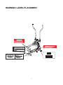
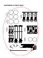
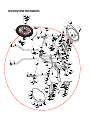
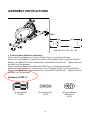
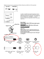
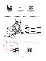
Air Elliptical
ITEM NO.: 1301
OWNER’S MANUAL
IMPORTANT: Read all instructions carefully before using this product.
owner’s manual for future reference.
Retain this
The specifications of this product may vary from this photo, subject to change without notice.
IMPORTANT: FOR NORTH AMERICA ONLY
To request product service and order
replacement parts, please call our
customer service department at:
1-866-924-1688
Monday through Friday, 8:00 AM-5:00 PM Pacific Standard Time,
or email us at: [email protected]
Please visit our website at www.paradigmhw.com.
Please have the following information ready when requesting for service:
Your name
Phone number
Model number
Serial number
Part number
Proof of Purchase
*Before returning this product to the store please contact
customer service at the contact number.
Paradigm Health & Wellness, Inc.
1189 Jellick Ave.
City of Industry, CA 91748, USA
1
TABLE OF CONTENTS
WARRANTY ------------------------------------------------------------------------------- 3
WARNING LABEL PLACEMENT ---------------------------------------------------- 4
IMPORTANT SAFETY INSTRUCTIONS ------------------------------------------- 5
PARTS LIST ------------------------------------------------------------------------------- 6
HARDWARE & TOOLS PACK -------------------------------------------------------- 8
OVERVIEW DRAWING ----------------------------------------------------------------- 9
ASSEMBLY INSTRUCTIONS --------------------------------------------------------- 10
OPERATING THE COMPUTER ------------------------------------------------------ 16
ADJUSTMENTS -------------------------------------------------------------------------- 17
MAINTENANCE -------------------------------------------------------------------------- 18
TROUBLESHOOTING ------------------------------------------------------------------ 19
WARM UP ---------------------------------------------------------------------------------- 20
PARTS REQUEST FAX FORM ------------------------------------------------------- 22
2
ONE YEAR LIMITED WARRANTY
Paradigm Health & Wellness, Inc. warrants to the original purchaser that this product is free
from defects in material and workmanship when used for the purpose intended, under the
conditions that it has been installed and operated in according to Paradigm Health &
Wellness, Inc.’s Owner’s Manual.
Paradigm Health & Wellness, Inc.’s obligation under this
warranty is limited to replacing free of charge, any parts which may prove to be defective
under normal home use.
This warranty does not include any damage caused by improper
operation, misuse or commercial application.
From the date of purchase, the product is
warranted to be free from defects for 1 (one) year.
All parts and workmanship, including
upholstery, foam, ball bearings, pulleys, cables, shocks, all tension mechanisms, wheels,
pedals and hardware are to be free from defects for 90 days.
This warranty is offered only
to the original owner and is not transferable. Proof of purchase is required.
This warranty
is offered only to the original owner and is not transferable.
Ordering Replacement Parts
Replacement parts can be ordered by calling or emailing our customer service department
[email protected]
1-866-924-1688
Monday through Friday, 8:00 AM - 5:00 PM (PST).
When ordering replacement parts please have the following information ready:
1. Owner’s Manual
2. Model Number
3. Description of Parts
4. Part Number
5. Date of Purchase
3
WARNING LABEL PLACEMENT
8
9059 8 01301
4
Serial No.:111054130100001
111054130100001
MADE IN CHINA / FABRIQUE EN CHINE
4
IMPORTANT SAFETY INSTRUCTIONS
Basic precautions should always be followed, including the following safety
instructions when using this equipment: Read all instructions before using this
equipment.
1.
Read all the instructions in this manual and do warm up exercises before using this
product.
2. Before exercise, in order to avoid injuring your muscles, warm-up exercise for every
muscle group is highly recommended. Please refer to the Warm Up pages for pre and
post workout.
3. Please make sure all parts are not damaged and functioning before use. This product
should be placed on a flat surface when using. Using a mat or other covering material
on the ground is recommended.
4. Please wear proper clothes and shoes when using this equipment; do not wear clothes
that might catch any part of the equipment.
5. Do not attempt any maintenance or adjustments other than those described in this
manual. Should any problems arise, discontinue use and consult an Authorized
Service Representative.
6. Be careful when stepping on or leaving the pedals. Make sure to hold on to the
handlebars when mounting and dismounting. When mounting, make sure the pedal is
at its lowest point before you step on. While in use, please onto the handlebars and use
both the pedals and the handlebars in tandem to insure a smooth, effective workout.
7. Do not use the product outdoors.
8. This product is for household use only.
9. Only one person should be on the product while in use.
10. Keep children and pets away from the product while in use. This machine is designed
for adults only. This product requires a minimum of 6 feet of space for safe operation.
11. If you feel any chest pains, nausea, dizziness, or short of breath, you should stop
exercising immediately and consult your physician before continuing.
12. The maximum weight capacity for this product is 250 lbs/114 kgs.
WARNING: Before beginning any exercise program consult your physician.
This is especially important for the persons who are over 35 years old or who have
pre-existing health problems.
Read all instructions before using any fitness
equipment.
CAUTION: Read all instructions carefully before operating this product.
Retain this Owner’s Manual for future reference.
5
PARTS LIST
No.
Description
Qty No.
Description
Qty
001
Main Frame 900x205x630
1 027
Left Handrail Arm Ø25x2x973
1
002
Rear Stabilizer Ø50x1.5x540
1 028
Handrail Arm Height Adjustment
Knob M8
2
003
Front Stabilizer End Cap Ø50
2 029
Handrail Arm Foam Grip
Ø23x5x310
2
004
Bolt M10x60
4 030
Handrail Arm End Cap Ø25
2
005
Cap Nut M10
4 031
Sensor with Wire L=900
1
006
Curve Washer Ø20xØ10.5
4 032
Computer M1202
1
007
Front Stabilizer Ø50x1.5x540
1 033
Nylon Nut M6
2
008
Transport Wheel Ø23x32
2 034
Tension Control Knob I001-SJ6
(L=260)
1
009
Right Handrail Ø32x580x1.5
1 035L Left Cover 695x365
1
010
Left Handrail Ø32x580x1.5
1 035R Right Cover 695x365
1
011
Foot Bar 30x30x1.5x637
2 036
Washer Ø28xØ16.2x0.3
2
012
037
013
Nylon Nut M10
6 038
Cap 14#
2
014
Cap 17#
4 039
Rear Stabilizer End Cap Ø50
2
015L Bolt for left Crank Ø16x129
1 040
Fan Wheel Ø500x56
1
015R Bolt for right Crank Ø16x129
1 041
Fan Wheel Axle M10x154
1
016
10 042
Nut M10
4
017L Nylon Nut for left Crank 1/2”
1 043
Flange Nut M10
2
017R Nylon Nut for right Crank 1/2”
1 044
Eyebolt M6x50
2
018
Spring Washer Ø20xØ13.5
2 045
Tension Bracket Ø6.5
2
019
Bolt 3/8"x20
2 046
Nut M6
2
020
Spring Washer Ø16xØ10.2x3
2 047
Strap 1150x17
1
021
Washer Ø28x4
2 048
Handrail Arm Plastic Bushing
Ø32
2
022
Rotation Rod Ø15.8x373
1 049
Handrail End Cap Ø32
2
023L Left Foot Pedal 35x150x40
1 050
Powder Metal Bushing Ø18
4
023R Right Foot Pedal 35x150x40
1 051
Bolt M10x55
2
024
Bolt M10x45
4 052
Chain
1
025
Chain Pulley with Crank
Ø160+65x1/2
1 053
Screw ST4.8x19
1
026
Right Handrail Arm Ø25x2x973
1 054
Spring Ø10x1.8x32
1
Powder Metal Bushing Ø28x16
6
PARTS LIST (cont.)
No.
Description
Qty No.
Description
Qty
055
Washer Ø40xØ24
1 066
Plastic Clip 29.5x26.5x15
1
056
Notched Bearing Nut
1 067
Adjustable Leveler M8x45
2
057
Bearing
2 068
Nut M8
2
058
Bearing Cup
2 069
Sensor Bracket
1
059
Slotted Bearing Nut
1 070
Small Magnet
1
060
Washer Ø35
1 071
Wire Plug Ø12
1
061
Hexagon Nut Ø45x12
1 072
Foot Pedal Support Bracket
2
062
Screw ST4.8x39
7 073
Bolt M8x43
4
063
Phillips Self Drilling Screw
ST4.8x19
3 074
Washer Ø8
4
064
Bolt M6x48
2 075
Nylon Nut M8
4
065
Cover Cap (oval 85x64xØ25)
2 076
Cap 19#
2
7
HARDWARE & TOOLS PACK
STEP 1
(14) Cap 17#
4 PCS
(76) Cap 19#
2 PCS
L
R
STEP 3
STEP 2
STEP 4
8
62
65 62
63
62
9
15L
73
62
60 57
61 59
36 16 11
72
63
23L
19
57 55
28
20
21 16
74
75
52
14 51
50
16 18
17L 76
70
13
25
58 56
24
35L
39
10
4
6
49
5
50 13
48
38
14
2
39
53
34
6
5
54
16
5
16
67
18
75
76 17R
67
68
1
27
74
13
71
16
6
32
16 36
13
50
3
16
4
48
47
42
21
15R
72 11 50 51
73
14 13
44 42
23R
8 33
7
24
64
68
3
28
22
26
43
29
29
45 46
30
30
65
62
49
9
14
20
38
40
62
35R
19
66
63
41
44 43
42 45 46
OVERVIEW DRAWING
ASSEMBLY INSTRUCTIONS
4
5
6
5
6
6
7
Tool:
5 1
2
Multi Hex Tool 13#, 17#, 19#
4
1. Front and Rear Stabilizers Installation
Position the Front Stabilizer (7) in front of Main Frame (1) and align bolt holes.
Attach the Front Stabilizer (7) onto the front curve of the Main Frame (1) with two M10x60
Bolts (4), two Ø20xØ10.5 Curve Washers (6), and two M10 Cap Nuts (5). Tighten nuts with
the Multi Hex Tool provided.
Position the Rear Stabilizer (2) behind the Main Frame (1) and align bolt holes.
Attach the Rear Stabilizer (2) onto the rear curve of the Main Frame (1) with two M10x60
Bolts (4), two Ø20xØ10.5 Curve Washers (6), and two M10 Cap Nuts (5). Tighten nuts with
the Multi Hex Tool provided.
Hardware (STEP 1):
(4) Bolt M10x60
4 PCS
(5) Cap Nut M10
4 PCS
10
(6) Curve Washer
Ø20xØ10.5
4 PCS
19
20 21
1
22
10
73
14
72
14
Tool:
15L 36
11
51
21 20
13
74 75
11
74
76
72
75
18
9
14
18 17L
76
25
17R
2 Allen Wrenches 6#
19
51
14
73
36 15R
Allen Wrench 8#
Multi Hex Tool 13#, 17#, 19#
2. Left/Right Handrails and Foot Bars Installation
Remove two M10x18 Bolts (19), two Ø16xØ10.2x3 Spring Washers (20), two Ø28x5
Washers (21), and two Ø28xØ16.2x0.3 Washers (36). Remove bolts with two 6# Allen
Wrenches provided.
Place the Ø15.8x376 Rotation Rod (22) into the hole of the Main Frame (1). Slide the
Left/Right Handrails (10, 9) onto the Ø15.8x376 Rotation Rod (22) and secure in place with
two M10x18 Bolts (19), two Ø16xØ10.2x3 Spring Washers (20), two Ø28x5 Washers (21),
and two Ø28xØ16.2x0.3 Washers (36) that were removed. Tighten bolts with two 6# Allen
Wrenches provided.
Install four 17# Caps (14) onto the M10x55 Bolts (51) and M10 Nylon Nuts (13) on the both
right and left sides of the Foot Bars (11).
Insert a Ø16x129 Bolt for right Crank (15R) and put the Ø28xØ16.2x0.3 Wave Washer (36)
through the right side of the Foot Bar (11). Put a Ø20xØ13.5 Spring Washer (18) on the
bolt, then pass it through the right Crank (25), and secure the bolt with a 1/2” Nylon Nut for
right Crank (17R). Tighten bolt and nylon nut with the 8# Allen Wrench and Multi Hex Tool
provided. Install two 19# Caps (76) onto both 1/2” Nylon Nuts for right/left Crank
(17R, 17L). Repeat this procedure for the left side assembly.
Please note:
Before you put the 1/2” Nylon Nut for right Crank (17R) and a Ø20xØ13.5 Spring Washer (18)
on the right side of the Foot Bar (11), make sure the Ø16x129 Bolt for right Crank (15R) had
been screwed to the end position with the Right Foot Bar (11).
Attach two Foot Pedal Support Brackets (72) onto both right and left sides of the Foot Bars
(11) with four M8x43 Bolts (73), four Ø8 Washers (74), and four M8 Nylon Nuts (75).
11
Tighten bolts and nylon nuts with the 6# Allen Wrench and Multi Hex Tool provided.
15L LEFT
15R RIGHT
In order to install the hinge bolt properly, keep it
perfectly straight when the bolt goes through the
pedal tubing and the crankshaft. If the hinge bolt
is connected to the crankshaft at an angle,
damage to both the hinge bolt and the crankshaft
may occur.
CORRECT
INCORRECT
INCORRECT
Right Bolt
Right Crank
Left Crank
Left Bolt
Important:
Screw Right Bolt (15R) into right crank
clockwise!
Screw Left Bolt (15L) into Left crank
counter-clockwise!
Important:
Please make sure the right bolt matches up
with the right crank and the left bolt matches
up with the left crank.
If reversed the cranks may become damaged
or stripped.
L
Hardware (STEP 2):
(36) Washer (18) Spring Washer (17L) Nylon Nut for
Ø28xØ16.2x0.3
Ø20xØ13.5
left Crank 1/2”
2 PCS
2 PCS
1 PC
R
(15L) Bolt for left Crank
Ø16x129
1 PC
(15R) Bolt for right Crank
Ø16x129
1 PC
(17R) Nylon Nut for
right Crank 1/2”
1 PC
12
(14) Cap 17#
4 PCS
(76) Cap 19#
2 PCS
(73) Bolt M8x43
4 PCS
(74) Washer Ø8
4 PCS
(75) Nylon Nut M8
4 PCS
․․․․․․․․․․․․․․․․․․․․․․․․․․․․․․․․․․․․․․․
Tool:
23L
24
11
23R
Multi Hex Tool 13#, 17#, 19#
11
13
3. Right and Left Foot Pedals Installation
Attach the Right Foot Pedal (23R) onto the Foot Bar (11) with two M10x45 Bolts (24) and
two M10 Nylon Nuts (13). Tighten nylon nuts with the Multi Hex Tool provided.
Use the same procedure to attach the Left Foot Pedal (23L) onto the other Foot Bar (11).
Hardware (STEP 3):
(24) Bolt M10x45
4 PCS
(13) Nylon Nut M10
4 PCS
13
27
28
10
48
38
26
48
38
28
9
4. Right/Left Handrail Arms Installation
Insert the Right Handrail Arm (26) into the Handrail Arm Plastic Bushing (48) on the tube of
the Right Handrail (9) and then attach the M8 Handrail Arm Height Adjustment Knob (28)
onto the tube of the Right Handrail (9) by turning it in a clockwise direction to lock the Right
Handrail Arm (26) in the suitable position. Install a 14# Cap (38) onto the nut on the Right
Handrail (9). Use the same procedure to attach the Left Handrail Arm (27) into the Handrail
Arm Plastic Bushing (48) on the tube of the Left Handrail (10).
Cap (STEP 4):
(38) Cap 14#
2 PCS
14
32
1
31
68
68
67
5. Computer and Adjustable Levelers Installation
Connect the Sensor Wire (31) to the wire that comes from the Computer (32). Place the
Computer (32) onto the plate on the Main Frame (1) then slide it down to lock in position.
Attach two M8x45 Adjustable Levelers (67) onto the Main Frame (1) with M8 Nuts (68).
15
OPERATING THE COMPUTER
SPECIFICATIONS:
TIME---------------------------------------------------- 00:00-99:59 MIN: SEC
SPEED------------------------------------------------- 0.0-99.9 MPH
DISTANCE-------------------------------------------- 0.00-99.99 MILE
CALORIES-------------------------------------------- 0-9999 CAL
FUNCTIONS AND OPERATIONS:
AUTO ON /OFF: When you start to exercise or press the MODE button on the computer, the
computer will turn on. If you do not use the equipment for 4 minutes, the power will shut off
automatically.
SCAN: Press the MODE button until the arrow points to SCAN, the computer will
automatically scan through the functions every 6 seconds.
TIME: Press the MODE button until the arrow points to TIME, the computer will display your
elapsed workout time in minutes and seconds.
SPEED: Press the MODE button until the arrow points to SPEED, the computer will display
the current training speed.
DISTANCE: Press the MODE button until the arrow points to DISTANCE, the computer will
display the cumulative distance traveled during workout.
CALORIES: Press the MODE button until the arrow points to CALORIES, the computer will
display the total calories burned during workout.
(This data is a rough guide for comparison of different exercise sessions and should not be
used in medical treatment).
RESET: Press and hold the MODE button for 4 seconds, all data values will clear to zero.
HOW TO INSTALL THE BATTERIES:
1. Remove the battery cover on the back of the computer.
2. Place two "SIZE-AA" batteries into the battery housing.
3. Insure batteries are correctly positioned and battery springs are proper contact with
batteries.
4. Re-install the battery cover.
5. If the display is illegible or only partial segment appear, remove batteries and wait 15
seconds before reinstalling.
16
ADJUSTMENTS
Adjusting the Tension Control Knob
To increase the tension, turn the tension control knob
in a clockwise direction.
To decrease the tension, turn the tension control knob
in a counterclockwise direction.
Tension Control Knob
After prolong use of the elliptical trainer, the strap will
begin to stretch out and it will become necessary to
tighten the strap for optimum performance.
1. Before tightening the strap the tension knob must
be set to its lowest setting. To do this turn the
knob in a counter-clockwise direction until it
becomes difficult to continue turning it.
2. Undo the buckle of the plastic clip and then pull the
top strap at the front of the unit away from the unit
to tighten it. Only minimal tightening should be
required. Finally, lock the buckle of the plastic
clip.
3. Now with the strap tightened and without changing
the tension when you get on you should feel a
slight bit of tension (i.e. the flywheel should not turn
freely). When you are satisfied with the base level
tension turn the tension knob clockwise and
continue exercising like normal.
17
Adjusting the Rear Stabilizer End Cap
or M8x45 Adjustable Leveler
Turn the rear stabilizer end cap on the rear
stabilizer or M8x45 adjustable leveler on
the main frame as needed to level the
elliptical trainer.
M8x45
Adjustable Leveler
Rear Stabilizer End Cap
Adjusting the Handrail Arms Height
Turn the handrail arm height adjustment
knob in a counterclockwise direction to
release the handrail arm and then slide the
handrail arm up or down slightly to the
desired hole for the suitable position.
Lock the handrail arm in place by
tightening the handrail arm height
adjustment knob in a clockwise direction.
Handrail Arm Height
Adjustment Knob
MAINTENANCE
Cleaning
The elliptical trainer can be cleaned with a soft cloth and any mild detergent. Do not use
abrasives or solvents on plastic parts. Please wipe your perspiration off the elliptical trainer
after each use. Be careful not get excessive moisture on the computer display panel as this
might cause an electrical hazard or electronics to fail.
Please keep the elliptical trainer, specially, the computer console, out of direct sunlight to
prevent screen damage.
Please inspect all assembly bolts and pedals on the machine for proper tightness every
week.
Storage
Store the elliptical trainer in a clean and dry environment away from children.
18
TROUBLESHOOTING
PROBLEM
There is no display on the computer
console.
The elliptical trainer makes a squeaking
noise when in use.
Tension adjustment doesn't work.
SOLUTION
1. Remove the Computer (32) and verify the
wire that comes from the Computer (32) is
properly connected to the wire that comes
from the Main Frame (1).
2. Check if the batteries are correctly
positioned and battery springs are in proper
contact with batteries.
3. The batteries in the computer console may
be dead. Change to new batteries.
The bolts may be loose on the elliptical trainer,
please inspect the bolts and tighten the loose
bolts.
Undo the buckle of the plastic clip and pull the
top strap to re-tighten the tension belt.
After long use, the chain may get loose and
start to have clicking noise. You may open
the Right Cover (35R) to reach the Nut M6
(46). Tighten the chain by screwing the
Nut M6 (46) clockwise.
Clicking Noise.
The elliptical is not sturdy enough.
Make sure the middle knobs touch the ground
and the elliptical is leveled by turning the Rear
Stabilizer End Cap (39). Please refer to page
19.
19
WARM UP
The WARM-UP is an important part of any workout. You should begin every session by
stretching your muscles to prepare your body for more strenuous exercise. This will help
increasing your circulation and pulse rate, and deliver more oxygen to your muscles.
HEAD ROLLS
Rotate your head to the right for one count, you should feel a
stretching sensation up the left side of your neck. Then rotate your
head back for one count, stretching your chin to the ceiling and
letting your mouth open. Rotate your head to the left for one count,
then drop your head to your chest for one count.
SHOULDER LIFTS
Lift your right shoulder toward your ear for one count. Then lift your
left shoulder up for one count as you lower your right shoulder.
SIDE STRETCHES
Open your arms to the side and lift them until they are over your head.
Reach your right arm as far toward the ceiling as you can for one
count. Repeat this action with your left arm.
QUADRICEPS STRETCH
With one hand against a wall for balance, reach behind you and pull
your right foot up. Bring your heel as close to your buttocks as
possible. Hold for 15 counts and repeat with left foot.
20
INNER THIGH STRETCH
Sit with the soles of your feet together and your knees pointing
outward. Pull your feet as close to your groin as possible.
Gently push your knees toward the floor. Hold for 15 counts.
TOE TOUCHES
Slowly bend forward from your waist, letting your back and
shoulders relax as you stretch toward your toes. Reach as far as
you can and hold for 15 counts.
HAMSTRING STRETCHES
Extend your right leg. Rest the sole of your left foot
against your right inner thigh. Stretch toward your toe as
far as possible. Hold for 15 counts. Relax and then
repeat with left leg.
CALF/ACHILLES STRETCH
Lean against a wall with your left leg in front of the right and
your arms forward. Keep your right leg straight and the left
foot on the floor; then bend the left leg and lean forward by
moving your hips toward the wall. Hold, then repeat on the
other side for 15 counts.
21
Paradigm Health & Wellness, Inc.
PARTS REQUEST FAX FORM
Please fax this form to (1-626-810-2166)
OR YOU CAN EMAIL CUSTOMER SERVICE REQUESTS TO
[email protected]
NAME: _________________________________________________________________
ADDRESS: ______________________________________________________________
CITY ______________ STATE ______________ ZIP ___________________
TELEPHONE: (Day) _______________________________________________________
(Night) ______________________________________________________
(Email Address) ______________________________________________
SERIAL#: ___________________________________________________
MODEL#: ___________________________________________________
PURCHASE DATE: _______________________________________________________
PURCHASE FROM: ______________________________________________________
PART #
DESCRIPTION
“YOUR ORDER WILL BE PROCESSED WITHIN 3 BUSINESS DAYS”
OFFICIAL USE ONLY
SHIP DATE: ___________________________________________
TRK #: _______________________________________________
BACK ORDER: ________________________________________
22
QTY